EP0310522B1 - Vorrichtung zur intensiven und kontrollierten Herstellung von Mikroorganismen durch Photosynthese - Google Patents
Vorrichtung zur intensiven und kontrollierten Herstellung von Mikroorganismen durch Photosynthese Download PDFInfo
- Publication number
- EP0310522B1 EP0310522B1 EP88402482A EP88402482A EP0310522B1 EP 0310522 B1 EP0310522 B1 EP 0310522B1 EP 88402482 A EP88402482 A EP 88402482A EP 88402482 A EP88402482 A EP 88402482A EP 0310522 B1 EP0310522 B1 EP 0310522B1
- Authority
- EP
- European Patent Office
- Prior art keywords
- tubes
- photobioreactor
- liquid medium
- group
- microorganisms
- Prior art date
- Legal status (The legal status is an assumption and is not a legal conclusion. Google has not performed a legal analysis and makes no representation as to the accuracy of the status listed.)
- Expired - Lifetime
Links
- 244000005700 microbiome Species 0.000 title claims description 49
- 230000029553 photosynthesis Effects 0.000 title claims description 18
- 238000010672 photosynthesis Methods 0.000 title claims description 18
- 238000004519 manufacturing process Methods 0.000 title claims description 16
- 239000007788 liquid Substances 0.000 claims description 37
- QVGXLLKOCUKJST-UHFFFAOYSA-N atomic oxygen Chemical compound [O] QVGXLLKOCUKJST-UHFFFAOYSA-N 0.000 claims description 21
- 239000001301 oxygen Substances 0.000 claims description 21
- 229910052760 oxygen Inorganic materials 0.000 claims description 21
- XLYOFNOQVPJJNP-UHFFFAOYSA-N water Substances O XLYOFNOQVPJJNP-UHFFFAOYSA-N 0.000 claims description 12
- -1 polyethylene Polymers 0.000 claims description 9
- 238000007654 immersion Methods 0.000 claims description 8
- 238000007872 degassing Methods 0.000 claims description 7
- 239000004743 Polypropylene Substances 0.000 claims description 6
- 229920001155 polypropylene Polymers 0.000 claims description 6
- 239000002184 metal Substances 0.000 claims description 5
- 230000001276 controlling effect Effects 0.000 claims description 4
- 229910003460 diamond Inorganic materials 0.000 claims description 4
- 239000010432 diamond Substances 0.000 claims description 4
- 230000001105 regulatory effect Effects 0.000 claims description 4
- 239000004698 Polyethylene Substances 0.000 claims description 3
- 239000011521 glass Substances 0.000 claims description 3
- 229920000573 polyethylene Polymers 0.000 claims description 3
- 229910001220 stainless steel Inorganic materials 0.000 claims description 2
- 239000010935 stainless steel Substances 0.000 claims description 2
- CURLTUGMZLYLDI-UHFFFAOYSA-N Carbon dioxide Chemical compound O=C=O CURLTUGMZLYLDI-UHFFFAOYSA-N 0.000 description 84
- 229910002092 carbon dioxide Inorganic materials 0.000 description 42
- 239000001963 growth medium Substances 0.000 description 37
- 239000002609 medium Substances 0.000 description 31
- 239000007789 gas Substances 0.000 description 17
- 125000006850 spacer group Chemical group 0.000 description 10
- 238000004140 cleaning Methods 0.000 description 8
- 235000015097 nutrients Nutrition 0.000 description 8
- 239000000523 sample Substances 0.000 description 8
- 230000033228 biological regulation Effects 0.000 description 7
- 239000001569 carbon dioxide Substances 0.000 description 7
- 238000011144 upstream manufacturing Methods 0.000 description 7
- IJGRMHOSHXDMSA-UHFFFAOYSA-N Atomic nitrogen Chemical compound N#N IJGRMHOSHXDMSA-UHFFFAOYSA-N 0.000 description 6
- 238000011161 development Methods 0.000 description 6
- 230000000243 photosynthetic effect Effects 0.000 description 6
- 239000011324 bead Substances 0.000 description 5
- 239000002028 Biomass Substances 0.000 description 4
- 238000009825 accumulation Methods 0.000 description 4
- 238000011109 contamination Methods 0.000 description 3
- 238000001816 cooling Methods 0.000 description 3
- 238000011049 filling Methods 0.000 description 3
- 238000007667 floating Methods 0.000 description 3
- 239000000463 material Substances 0.000 description 3
- 229910052757 nitrogen Inorganic materials 0.000 description 3
- XSQUKJJJFZCRTK-UHFFFAOYSA-N Urea Chemical compound NC(N)=O XSQUKJJJFZCRTK-UHFFFAOYSA-N 0.000 description 2
- 239000004202 carbamide Substances 0.000 description 2
- 230000008021 deposition Effects 0.000 description 2
- 238000013461 design Methods 0.000 description 2
- 238000004090 dissolution Methods 0.000 description 2
- 229920001971 elastomer Polymers 0.000 description 2
- 230000008030 elimination Effects 0.000 description 2
- 238000003379 elimination reaction Methods 0.000 description 2
- 229920002457 flexible plastic Polymers 0.000 description 2
- 229910052500 inorganic mineral Inorganic materials 0.000 description 2
- 239000011707 mineral Substances 0.000 description 2
- 239000000203 mixture Substances 0.000 description 2
- 230000000050 nutritive effect Effects 0.000 description 2
- 239000005416 organic matter Substances 0.000 description 2
- 238000012856 packing Methods 0.000 description 2
- 239000004800 polyvinyl chloride Substances 0.000 description 2
- 229920000915 polyvinyl chloride Polymers 0.000 description 2
- 230000005855 radiation Effects 0.000 description 2
- 238000011084 recovery Methods 0.000 description 2
- 150000003839 salts Chemical class 0.000 description 2
- 238000004062 sedimentation Methods 0.000 description 2
- 239000000243 solution Substances 0.000 description 2
- 230000003068 static effect Effects 0.000 description 2
- 238000003756 stirring Methods 0.000 description 2
- 230000008961 swelling Effects 0.000 description 2
- 230000009466 transformation Effects 0.000 description 2
- 241000894006 Bacteria Species 0.000 description 1
- 239000004215 Carbon black (E152) Substances 0.000 description 1
- 241000195493 Cryptophyta Species 0.000 description 1
- VVQNEPGJFQJSBK-UHFFFAOYSA-N Methyl methacrylate Chemical compound COC(=O)C(C)=C VVQNEPGJFQJSBK-UHFFFAOYSA-N 0.000 description 1
- 229910002651 NO3 Inorganic materials 0.000 description 1
- NHNBFGGVMKEFGY-UHFFFAOYSA-N Nitrate Chemical compound [O-][N+]([O-])=O NHNBFGGVMKEFGY-UHFFFAOYSA-N 0.000 description 1
- 229920005372 Plexiglas® Polymers 0.000 description 1
- 241001494715 Porphyridium purpureum Species 0.000 description 1
- 241001497549 Scenedesmus acutus Species 0.000 description 1
- 239000002253 acid Substances 0.000 description 1
- 230000006978 adaptation Effects 0.000 description 1
- 238000004026 adhesive bonding Methods 0.000 description 1
- 238000013019 agitation Methods 0.000 description 1
- 150000001413 amino acids Chemical class 0.000 description 1
- 150000003863 ammonium salts Chemical class 0.000 description 1
- 230000003321 amplification Effects 0.000 description 1
- 239000002518 antifoaming agent Substances 0.000 description 1
- 238000005842 biochemical reaction Methods 0.000 description 1
- 230000015572 biosynthetic process Effects 0.000 description 1
- 238000011138 biotechnological process Methods 0.000 description 1
- 239000006227 byproduct Substances 0.000 description 1
- 210000004027 cell Anatomy 0.000 description 1
- 230000001413 cellular effect Effects 0.000 description 1
- 230000008859 change Effects 0.000 description 1
- 210000003763 chloroplast Anatomy 0.000 description 1
- 238000009833 condensation Methods 0.000 description 1
- 230000005494 condensation Effects 0.000 description 1
- 239000000356 contaminant Substances 0.000 description 1
- 230000006866 deterioration Effects 0.000 description 1
- 238000010586 diagram Methods 0.000 description 1
- 238000009792 diffusion process Methods 0.000 description 1
- 238000001035 drying Methods 0.000 description 1
- 239000000806 elastomer Substances 0.000 description 1
- 238000000855 fermentation Methods 0.000 description 1
- 238000005188 flotation Methods 0.000 description 1
- 239000012530 fluid Substances 0.000 description 1
- 230000004907 flux Effects 0.000 description 1
- 210000004907 gland Anatomy 0.000 description 1
- 150000004676 glycans Chemical class 0.000 description 1
- 239000003630 growth substance Substances 0.000 description 1
- 229930195733 hydrocarbon Natural products 0.000 description 1
- 150000002430 hydrocarbons Chemical class 0.000 description 1
- 238000005286 illumination Methods 0.000 description 1
- 238000009776 industrial production Methods 0.000 description 1
- 238000002347 injection Methods 0.000 description 1
- 239000007924 injection Substances 0.000 description 1
- 230000014759 maintenance of location Effects 0.000 description 1
- 238000005259 measurement Methods 0.000 description 1
- 239000002207 metabolite Substances 0.000 description 1
- 238000000034 method Methods 0.000 description 1
- 230000004048 modification Effects 0.000 description 1
- 238000012986 modification Methods 0.000 description 1
- 238000003199 nucleic acid amplification method Methods 0.000 description 1
- 210000001916 photosynthetic cell Anatomy 0.000 description 1
- 239000004033 plastic Substances 0.000 description 1
- 229920003023 plastic Polymers 0.000 description 1
- 229920001282 polysaccharide Polymers 0.000 description 1
- 239000005017 polysaccharide Substances 0.000 description 1
- 229920002635 polyurethane Polymers 0.000 description 1
- 239000004814 polyurethane Substances 0.000 description 1
- 238000002360 preparation method Methods 0.000 description 1
- 239000000047 product Substances 0.000 description 1
- 239000002994 raw material Substances 0.000 description 1
- 238000004064 recycling Methods 0.000 description 1
- 230000004044 response Effects 0.000 description 1
- 230000035945 sensitivity Effects 0.000 description 1
- 239000007787 solid Substances 0.000 description 1
- 239000000126 substance Substances 0.000 description 1
- 239000006228 supernatant Substances 0.000 description 1
- 239000000725 suspension Substances 0.000 description 1
- 230000009182 swimming Effects 0.000 description 1
- 210000001519 tissue Anatomy 0.000 description 1
- 231100000331 toxic Toxicity 0.000 description 1
- 230000002588 toxic effect Effects 0.000 description 1
- 239000011782 vitamin Substances 0.000 description 1
- 235000013343 vitamin Nutrition 0.000 description 1
- 229940088594 vitamin Drugs 0.000 description 1
- 229930003231 vitamin Natural products 0.000 description 1
- 238000003466 welding Methods 0.000 description 1
Images




Classifications
-
- C—CHEMISTRY; METALLURGY
- C12—BIOCHEMISTRY; BEER; SPIRITS; WINE; VINEGAR; MICROBIOLOGY; ENZYMOLOGY; MUTATION OR GENETIC ENGINEERING
- C12M—APPARATUS FOR ENZYMOLOGY OR MICROBIOLOGY; APPARATUS FOR CULTURING MICROORGANISMS FOR PRODUCING BIOMASS, FOR GROWING CELLS OR FOR OBTAINING FERMENTATION OR METABOLIC PRODUCTS, i.e. BIOREACTORS OR FERMENTERS
- C12M21/00—Bioreactors or fermenters specially adapted for specific uses
- C12M21/02—Photobioreactors
-
- C—CHEMISTRY; METALLURGY
- C12—BIOCHEMISTRY; BEER; SPIRITS; WINE; VINEGAR; MICROBIOLOGY; ENZYMOLOGY; MUTATION OR GENETIC ENGINEERING
- C12M—APPARATUS FOR ENZYMOLOGY OR MICROBIOLOGY; APPARATUS FOR CULTURING MICROORGANISMS FOR PRODUCING BIOMASS, FOR GROWING CELLS OR FOR OBTAINING FERMENTATION OR METABOLIC PRODUCTS, i.e. BIOREACTORS OR FERMENTERS
- C12M23/00—Constructional details, e.g. recesses, hinges
- C12M23/02—Form or structure of the vessel
- C12M23/06—Tubular
-
- C—CHEMISTRY; METALLURGY
- C12—BIOCHEMISTRY; BEER; SPIRITS; WINE; VINEGAR; MICROBIOLOGY; ENZYMOLOGY; MUTATION OR GENETIC ENGINEERING
- C12M—APPARATUS FOR ENZYMOLOGY OR MICROBIOLOGY; APPARATUS FOR CULTURING MICROORGANISMS FOR PRODUCING BIOMASS, FOR GROWING CELLS OR FOR OBTAINING FERMENTATION OR METABOLIC PRODUCTS, i.e. BIOREACTORS OR FERMENTERS
- C12M23/00—Constructional details, e.g. recesses, hinges
- C12M23/56—Floating elements
-
- C—CHEMISTRY; METALLURGY
- C12—BIOCHEMISTRY; BEER; SPIRITS; WINE; VINEGAR; MICROBIOLOGY; ENZYMOLOGY; MUTATION OR GENETIC ENGINEERING
- C12M—APPARATUS FOR ENZYMOLOGY OR MICROBIOLOGY; APPARATUS FOR CULTURING MICROORGANISMS FOR PRODUCING BIOMASS, FOR GROWING CELLS OR FOR OBTAINING FERMENTATION OR METABOLIC PRODUCTS, i.e. BIOREACTORS OR FERMENTERS
- C12M29/00—Means for introduction, extraction or recirculation of materials, e.g. pumps
- C12M29/20—Degassing; Venting; Bubble traps
- C12M29/22—Oxygen discharge
Definitions
- the subject of the present invention is a device for intensive and controlled production of microorganisms or biomass, by photosynthesis, on an industrial scale, comprising simple components and easy implementation.
- the invention applies to the production of any photosynthetic material, that is to say to any form of life capable of development and of photosynthesis in a suitable nutritive liquid medium in the presence of solar radiation and carbon dioxide, to the production of metabolites and polysaccharides possibly excreted by microorganisms.
- photosynthetic microorganisms mention may be made of plant tissues and all single-celled organisms containing chloroplasts, photosynthetic bacteria and microalgae.
- Photosynthesis is the transformation, thanks to solar energy, of carbon dioxide into hydrocarbon raw material, oxygen being the main by-product of this biochemical transformation.
- the culture and development of microorganisms by photosynthesis is carried out in a photobioreactor.
- a photobioreactor In order to ensure proper functioning of the photobioreactor and to ensure optimum development of microorganisms, it is necessary that a certain number of physical phenomena be controlled.
- the liquid medium containing the microorganisms must be constantly loaded with dissolved CO2 and nitrogen, the concentration of nitrogen and dissolved CO2 having to be maintained at an optimal level during the culture and development of the microorganisms.
- the temperature of the liquid medium containing the microorganisms, its salinity, its concentration of photosynthetic cells as well as its pH must be rigorously regulated.
- photobioreactors consist of a set of transparent tubes, arranged in the form of a raft above a large body of water (lagoon, pond, sea, swimming pool) serving as sources of cooling of the charged liquid medium. microorganisms circulating in the tubes.
- the presence of oxygen in the tubes can upset - or even be toxic to - microorganisms grown in the tubes.
- this self-cleaning bead system does not ensure 100% effective degassing of the photobioreactor culture tubes.
- the subject of the invention is precisely a device for the production of microorganisms, by photosynthesis, comprising one or more photobioreactors with tubes intended to be placed on a body of water, preventing any presence of gas pockets and in particular of oxygen in the air. inside the tubes.
- the subject of the invention is therefore a device for intensive and controlled production, by photosynthesis, of microorganisms suspended in a liquid medium comprising at least at least one photobioreactor intended to be placed on a body of water, comprising a first set of tubes, transparent to light, in which the liquid medium circulates, characterized in that the photobioreactor further comprises a second set of tubes disposed under the first set, the tubes of the first and second sets being made integral by means of removable spacers, regularly spaced, this second set being able to make the photobioreactor submersible or unsinkable; and in that the device also comprises means for controlling the second set of tubes with a view to whether or not the photobioreactor is immersed; at least one carbonator connected to the input of the photobioreactor to charge the liquid medium with CO2 necessary for photosynthesis; at least one degasser connected to the photobioreactor to eliminate from the liquid medium, in particular the oxygen produced by the micro-organisms and possibly the undissolved CO2; and at least one expansion tank connected to the
- the tubes of the first set are connected together so as to form a coil.
- the tubes of the second set are connected together so as to form another coil.
- the presence of the spacers makes it possible to make the two sets of tubes of the photobioreactor perfectly integral and to prevent in particular the misalignment of the tubes thus allowing, by linear entrainment of the liquid medium, up to the degasser, the circulation of the gas pockets possibly present in the tubes. of the first set, such as oxygen resulting from photosynthesis.
- the presence of the spacers promotes the circulation of these balls.
- the spacers are easy to install and prevent gluing or welding of the tubes together, an operation which prevents the change of a single tube in the event of deterioration of this tube.
- the photobioreactor when the temperature of the liquid loaded with microorganisms exceeds a higher set temperature, the photobioreactor is immersed thanks to the deflation of the tubes of the second set; this deflation is ensured using an automated system. Conversely, when the temperature of the liquid medium is lower than a minimum set temperature, the automaton controls the inflation of the tubes of the second set with compressed air.
- Immersion of the photobioreactor can also be ensured by introducing a relatively heavy liquid such as into the tubes of the second set and the flotation by injecting a light fluid other than air.
- the presence of spacers according to the invention also improves the thermal regulation of the photobioreactor, in particular when the tubes of the second set are intended to be inflated with compressed air, in order to make the photobioreactor float, and to be deflated, with a view to total or partial immersion of the photobioreactor.
- the tubes of the first set filled with liquid heavier than the tubes of the second all empty of air, may slip between two inflatable tubes and therefore remain in constant and total immersion.
- the degasser comprises a closed external enclosure, having a longitudinal axis, a U-shaped oxygen collecting duct, one of the branches of which is housed in the enclosure parallel to said axis and the base of which is situated on the side of the base of the enclosure, the end of the collecting conduit oxygen opening into the upper part of the enclosure, at least one supply pipe and at least one outlet pipe of the liquid medium opening into the lower part of the enclosure.
- a degasser prevents internal soiling of the tubes of the photobioreactor (by deposition of microorganisms) thus making the use of self-cleaning beads which are the subject of document FR-A-2 576 034 unnecessary.
- any static and constant presence of any gas inside the tubes of the first assembly thwarts the operation of the photobioreactor. This applies not only to the oxygen produced by the microorganisms but also for the carbon dioxide introduced into the liquid medium and which is necessary for the development of the microorganisms and for the air possibly used as the gas support gas. carbonic.
- the carbonator of the invention is a carbonator of the two-column type comprising an inlet column in which the liquid medium is charged with CO2 and an outlet column, connected to the inlet column, in which the liquid medium charged with CO2.
- the role of the first column is to charge the culture medium to the maximum with carbon dioxide and the second column is to avoid entraining carbon dioxide in the photobioreactor which has not dissolved in the liquid medium and possibly the air used as support gas for CO2.
- the inlet column advantageously comprises a dip tube for supplying CO2 into the liquid medium, the plunging end of which is made of glass or sintered stainless steel of variable porosity.
- a dip tube for supplying CO2 into the liquid medium, the plunging end of which is made of glass or sintered stainless steel of variable porosity.
- an internal packing of the first column can be provided.
- the expansion tank or tanks must, according to the invention have a shape such that there is no accumulation of organic matter and in particular of microorganisms, all of the microorganisms being generally recycled. In addition, these tanks must be transparent to light.
- the expansion tank (s) are transparent and formed of an enclosure with rounded edges, the upper end of which is closed by a diamond-tipped cover and the lower end of which has the form of a funnel.
- the shape of the tanks can make it possible to clarify culture during certain contamination: filling of this tank with culture, stopping circulation and sedimentation.
- the supernatant part containing the contaminants such as microalgae from 5 to 10 ⁇
- the sedimented part (representing the cultivated micro-algae) is recycled.
- the device for producing microorganisms, by photosynthesis, of the invention comprises one or more expansion tanks 2 of approximately 200 l intended to receive a solution of microalgae 1, injected with using a pump 4 in tube photobioreactors 6.
- These photobioreactors 6 are intended to be placed on the surface of a body of water 8.
- the number of these photobioreactors depends on the production of biomass envisaged.
- the tanks 2 serve to dampen any volume variations in the photobioreactors due to the possible accumulation of gas. Culture from all photobioreactors arrives in these tanks. Also, the latter constitute a volume representative of the entire culture medium 1 of the production device. It is at this level that the supply of microalgae and culture medium takes place, as will be seen later (FIG. 7).
- the culture medium supply lines 10 into the photobioreactors are each equipped with double column carbonators 12 in order to charge the culture medium 1 with carbon dioxide necessary for photosynthesis.
- the number of carbonators 12 is generally equal to the number of photobioreactors.
- the CO2 supply is made in a mixture with air, up to 80% by volume of CO2 in the mixture.
- a mixer-flow meter 14 mounted on the air supply line 16 and on the CO2 supply line 18 is provided at the gas inlet of each carbonator 12.
- a system 19 makes it possible to regulate the amount of CO2 introduced into photobioreactors as a function of solar energy.
- This production device further comprises a tank 20 used for the preparation, with stirring, of the nutrient medium necessary for the growth of microorganisms.
- This nutritive medium before being introduced, via a supply line 22 to the tanks 2 containing the microalgae, is filtered by two filters 24 and 26, of the Philippe type, ensuring respectively the passage of the mineral and organic elements, necessary for growth of microorganisms, 40 and 1 ⁇ m.
- a pump 28 injects the nutrient medium into the tanks 2.
- the microorganisms produced in the photobioreactors 6 are extracted at the outlet of each of the photobioreactors, via outlet pipes 30, using a volumetric pump 32.
- the flow rate of the withdrawal pump 32 from the culture medium 1 is equal to that of the nutrient medium injection pump 28 so that the culture volume in the photobioreactor remains constant.
- the microorganisms produced are recovered in a tank 34, with continuous stirring.
- degassers 36 are provided on each side of the photobioreactors 6 (ie two degassers per photobioreactor).
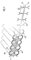
- the photobioreactors consist of a first set of parallel tubes 38 made of transparent flexible plastic material such as polyethylene. These tubes are intended to receive the culture medium 1 loaded with nutrients and CO2 necessary for the growth of microorganisms. They are approximately 15.8 m long and have a internal diameter of 63 mm.
- These tubes 38 are connected together at their two ends, as shown in FIG. 3, using two collectors respectively upstream 40 and downstream 42.
- These collectors 40 and 42 are made of polypropylene and include several compartments or elbow fittings 44.
- the total number of compartments 44 of the upstream and downstream collectors is equal to the number of tubes 38.
- Each compartment or fitting 44 of the upstream collector 40 comprises an inlet port 46 for receiving a first tube 38a and an outlet port 48 for receiving a second tube 38b.
- the tubes 38a and 38b are fixed to the manifold 40 using identical gland systems 50a and 50b respectively.
- two internal sleeves 52a and 52b are housed respectively in the tubes 38a and 38b and two external sleeves 54a and 54b, in which the tubes 38a and 38b are fitted, are respectively housed in the inlet ports 46 and exit 48 from compartments 44.
- the external sleeves 54a and 54b are each provided with a groove 56a and 56b in which screws 58a and 58b are fitted mounted on the connector 44, respectively at the inlet and at the outlet of the latter.
- the internal sleeves 52a, 52b and the external sleeves 54a, 54b are made of polypropylene.
- the assembly of the downstream collector 42 and the tubes 38 is identical in all respects to that of the upstream collector 40 and the tubes 38.
- Each photobioreactor 6 has a single line supply 10 of the culture medium, mounted at the single inlet 43 of the upstream collector 40, and a single outlet pipe 30 from said medium, mounted at the single outlet 45 of the collector 40, the inlet pipe 10 being mounted on the first tube 38 of the photobioreactor and the outlet pipe 30 on the last tube 38 of this same photobioreactor.
- each connector 44 of the upstream 40 and downstream 42 collector is provided with an orifice 60 used for the connection of degassers 36. This connection is ensured by means of flexible inlet 61 and outlet 63 conduits from the medium. culture ( Figures 2 and 5).
- the solution of microorganisms needs for its own growth to be regulated at a temperature ranging from 18 to 28 ° C, that is to say close to room temperature.
- each photobioreactor 6 is provided with a second set of tubes 62 placed below the tubes 38.
- These tubes 62 made of flexible plastic material, for example polyethylene, are connected to each other like the tubes 38, to the using an upstream collector 64 and a downstream collector 65, with bent compartments, to form a coil (FIG. 2).
- These tubes 62, 16.4 m long and 63 mm in internal diameter are intended to be inflated with compressed air, using a solenoid valve 66, thus forming a pneumatic support floating on the surface of the body of water 8.
- the solenoid valve 66 is controlled by an electronic control circuit 68 connected to thermal measurement probes 67 housed inside the tubes 38.
- the thermal probes When the temperature of the culture medium 1 contained in the tubes 38, measured by the probes 67, is higher than a maximum set temperature (29 ° C. for example), the thermal probes emit a first signal detected by the electronic circuit 68 controlling then the deflation of the tubes 62 by means of the solenoid valves 71. The deflation of the tubes 62 then causes the total or partial immersion, depending on the deflation rate, of the photobioreactors 6 in the area of water 8. Since the water is cooler than the ambient atmosphere and the culture medium present in the photobioreactors, the culture medium cools.
- the probes 67 When the immersed culture medium reaches a temperature, measured by the probes 67, below a minimum set temperature (for example 17 ° C), the probes 67 emit a second signal detected by the electronic circuit 68 then controlling the solenoid valve 66 in order to ensure the swelling of the tubes 62 with compressed air. The swelling of the tubes 62 then causes the photobioreactors 6 to float. The culture medium then heats up in the open air.
- a minimum set temperature for example 17 ° C
- All the supply and outlet lines from the culture medium, compressed air, etc. and all the electrical connections (probes 67), connected between the photobioreactors and the other components of the production device such as degassers, carbonators, compressors etc ... are necessarily flexible to be compatible with the immersion or not of photobioreactors.
- the components other than the photobioreactors are mounted on a hard pontoon 69 as shown diagrammatically in FIG. 2, floating on the surface of the water 8.
- spacers 70 maintain the tubes 38 and 62 in place.
- These spacers 70 are removable and regularly spaced, about every 60 cm ( Figure 2).
- These spacers 70 are made of polypropylene and have the shape of Y whose tails are supported by support rods 72 in particular made of polypropylene.
- the supports 72 are fitted with orifices 74 in which the tails of the Y 70s are housed.
- the Ys arranged on either side of the rods 72 and serving respectively to hold the tubes 38 and 62 are fixed head to tail .
- the Y 70s are connected together using flexible rubber connections 76, mounted on the branches of the Y.
- the tubes 38 and 62 are arranged between two consecutive Y 70s, their retention in place being ensured by the elastic connections 76 and support 72.
- degassers 36 are used, advantageously produced as shown in FIG. 5 and connected to each end of the tubes 38.
- Each degasser 36 comprises an external enclosure 78 of cylindrical shape, comprising a longitudinal axis 79, provided with a bottom 80 and closed by a cover 81, as well as a U-shaped duct 82 used to collect the oxygen and the other gases present in the culture medium 1.
- This U-shaped tube 82 has a branch 84 housed along the longitudinal axis 79 of the enclosure 78. The end 85 of this branch 84 collecting the oxygen coming from the culture medium opens into the part upper part of the enclosure 78, near the cover 81.
- the base 86 of the U-shaped duct is parallel to the bottom 80 of the enclosure 78.
- the direction of circulation of the oxygen in the degasser 36 is indicated by the arrows F2.
- the flexible supply lines 61 of the culture medium charged with oxygen (generally 60% by volume of oxygen) and the flexible supply lines 63 of the deoxygenated and more generally degassed culture medium open at the base of the degasser and are fixed to the bottom 80 of enclosure 78.
- the degassers 36 are supported by feet 87 whose height H is adjusted so that the enclosure 78 of the degassers is never filled with culture medium, whether the photobioreactors are immersed or float.
- the culture height in the tubes 63 is determined by the internal pressure in the tubes 38.
- the microorganisms of the culture medium 1 have a permanent need for CO2 hence the need to constantly charge the culture medium with dissolved CO2.
- a carbonator 12 is used connected to the inlet of each photobioreactor as shown in Figure 6.
- This carbonator comprises a cylindrical inlet column 88, closed at its two ends and possibly containing a packing 90 of the Raschig ring or Bert saddle type.
- the culture medium arriving at the base of the column 88, is charged with CO2 introduced using a dip tube 92, the dip end 94 of which is made of sintered glass of variable porosity in order to '' improve the dissolution of CO2 in the liquid medium 1.
- This inlet column 88 is connected at its upper part to an outlet column 96 in which the liquid medium charged with CO2 subverts.
- the purpose of this column 96 is to prevent the entrainment of CO2 and possibly of the undissolved support gas in the culture medium towards the associated photobioreactor.
- a pipe 98 for evacuating the undissolved CO2 is provided at the top of the outlet column 96.
- the arrows F3 indicate the direction of circulation of the liquid medium 1 in the carbonator.
- the expansion tanks 2 like the other parts of the production device, also help to prevent the deposition of microorganisms in the tubes 38 of the photobioreactors and therefore improve the efficiency of the photobioreactors. To this end, tanks are advantageously used as shown in FIG. 7.
- the tank shown comprises a rectangular enclosure 100, the lower end 102 of which has the form of a funnel; this tank has the shape of a hopper or silo and its flared bottom allows the sedimentation and the total recycling of the organic matter in suspension (micro-organisms + products excreted by the micro-organisms).
- the tank has no edges or sharp edges and the corners are rounded to avoid excessive fixation of microorganisms and facilitate cleaning. It further comprises a cover 104 with a diamond point in order to avoid the accumulation of condensation; the tip of the cover is directed towards the top of the tank.
- the cover 104 is fixed to the enclosure 100 by metal clips 106 or butterfly screws.
- An O-ring 108 seals between the enclosure and the cover.
- the enclosure 100 of the tank and its cover 104 are transparent in order to allow observation but also to combat the contamination of certain protists sensitive to light; it is made of Plexiglass R or PVC (polyvinyl chloride).
- an inlet 110 for the culture allows central filling of the hopper with microorganisms.
- supply lines 112, 22, 114 and 116 are provided for respectively introducing into the tank 2 the culture medium during filling of the device, the culture medium during continuous operation, the pH regulator (acid or basic) and the defoaming agent.
- a high level probe 118 and a low level probe 120 make it possible respectively to prevent overflow or complete emptying of the tank 2 during the continuous operation of the general production device.
- first flat metal grid 122 and a second metal grid 124 are provided.
- the first grid of 1 cm mesh allows, when using self-cleaning polyurethane beads, the recovery of these beads.
- the second grid, 1 mm mesh, diamond point, allows the recovery of large cellular aggregates from self-cleaning by the balls; the tip of the grid is directed towards the bottom of the tank.
- the start of the culture medium towards the photobioreactors is ensured by the line 126, at the lower end 102 of the tank, a stop valve 128 being mounted on this line 126.
- It includes a pyranometer 130 delivering an electrical voltage of 0 to 10 mV representing the variations in light energy.
- This electrical signal is amplified using a variable gain amplifier 132, between 0 and 5V.
- the maximum amplification represents the flow rate of the valve 134 at full opening, mounted on the pipe 18 (FIG. 1).
- a circuit 136 of the RC type makes it possible to damp the response of the valve 134 to light variations of very short duration.
- an amplifier 132 with variable gain allows a modification of the sensitivity of the system 19, that is to say the choice of the level of light intensity determining the complete opening of the valve 134.
- a setting of the threshold S of zero makes it possible to choose the solar energy threshold triggering the opening of the valve 134; this adaptation makes it possible to take account of the point of compensation for photosynthetic microorganisms.
- the amplified signal leaving circuit 136 is directed to an electronic valve control circuit 138, the valve 134 being a model 5850TR electronic valve.
- the valve can be controlled manually by an external power supply 140 (0-5V) or automatically by means of a computer 142.
- An adapter circuit 144 is provided between the computer and the RC circuit.
- This regulation system 19 makes it possible, as shown in part b of FIG. 8, to supply the culture medium with CO2 as a function of variations in the light energy E over time t, expressed in minutes.
- Curve I represents the variations in solar energy
- curve II represents the variations in the supply of CO2 to the culture medium
- curve III represents the variations in unconsumed CO2.
- the photosynthetic activity (fixation of CO2 by microorganisms) is proportional to the light intensity.
- intensity of the solar flux is variable during the day: minimum in the morning and in the evening, maximum when the sun is at its zenith.
- a constant supply of CO2 therefore leads in the morning and in the evening to significant losses of CO2 (low photosynthetic activity) and sometimes to a limitation of photosynthesis by lack of CO2 when the light intensity is maximum.
- CO2 regulation therefore allows CO2 savings since its supply is proportional to biological demand.
- the production device according to the invention can be used for the development and culture of plant cells or unicellular algae such as those described in the publication by G. Gudin and C. Thépenier "Bioconversion of solar energy into organic chemicals by microalgae” published in Advances in Biotechnological Processes 6, pp. 73-110 from 1986.
- the nutrient media of the latter contain various mineral salts, metal salts, amino acids, vitamins and growth regulators. Examples of nutrients which can be used in the invention are in particular illustrated in documents FR-A-2 324 224 and FR-A-2 361 060.
- the production device described above allows in particular an industrial production of approximately 60 tonnes per year of biomass such as Porphyridium cruentum, Scenedesmus acutus, Dunalulla, and this, industrially, using tubular photobioreactors distributed over a water surface of 1 ha, with an operation of 300 days per year, a period of solar illumination of 12 hours on average per day (which corresponds to a solar energy of 950 W / m2), a fixed quantity of CO de of 56,000 m3 per year , or 110 tonnes per year, and a quantity of nutrient medium per day of 50 m3, which corresponds to approximately 30 kg of urea per day, the quantity of oxygen released into the atmosphere being 56,000 m3 per year, or 154 tonnes per year.
Landscapes
- Health & Medical Sciences (AREA)
- Life Sciences & Earth Sciences (AREA)
- Engineering & Computer Science (AREA)
- Zoology (AREA)
- Organic Chemistry (AREA)
- Bioinformatics & Cheminformatics (AREA)
- Chemical & Material Sciences (AREA)
- Wood Science & Technology (AREA)
- Genetics & Genomics (AREA)
- Biotechnology (AREA)
- Sustainable Development (AREA)
- Microbiology (AREA)
- Biochemistry (AREA)
- General Engineering & Computer Science (AREA)
- General Health & Medical Sciences (AREA)
- Biomedical Technology (AREA)
- Clinical Laboratory Science (AREA)
- Molecular Biology (AREA)
- Apparatus Associated With Microorganisms And Enzymes (AREA)
Claims (15)
- Vorrichtung zur intensiven und kontrollierten Herstellung, durch Photosynthese, von Mikroorganismen in Suspension in einem flüssigen Milieu, welche mindestens einen Photobioreaktor (6) umfaßt, der dazu bestimmt ist, auf einer Wasserfläche (8) angeordnet zu sein, der eine erste Röhreneinheit (38) umfaßt, die bei Licht transparent sind und in welchen das flüssige Milieu (1) zirkuliert, dadurch gekennzeichnet, daß der Photobioreaktor außerdem eine zweite Röhreneinheit (62) umfaßt, die unter der ersten Einheit gelagert ist, wobei die Röhren der ersten und der zweiten Einheit mithilfe von abnehmbaren Zwischenlagen (70) mit regelmäßigen Abständen festgehalten werden, diese zweite Einheit ist fähig, den Photobioreaktor in Wasser versenkbar oder nicht versenkbar zu machen; und daß die Vorrichtung auch Geräte zur Steuerung (66, 67, 68) der zweiten Röhreneinheit hinsichtlich dem Eintauchen oder nicht Eintauchen des Photobioreaktors (6) umfaßt; mindestens einen Karbonateur (12) der am Eingang (10) des Photobioreaktors (6) angeschlossen ist, um das flüssige Milieu mit dem für die Photosynthese notwendigen CO₂ zu beladen; mindestens einem Entgaser (36), der an dem Photobioreaktor angeschlossen ist, um aus dem flüssigen Milieu (1) besonders den von den Mikroorganismen produzierten Sauerstoff zu beseitigen; und mindestens einen Ausdehnungsbehälter (2), der an dem Photobioreaktor (6) angeschlossen ist, um die eventuellen Volumenänderungen in dem Photobioreaktor (6) auszugleichen.
- Verfahren gemäß Anspruch 1, dadurch gekennzeichnet, daß die Zwischenlagen (70), welche eine Y-Form aufweisen, mit ihrem Endstück auf mindestens einer starre Stütze (72) montiert sind, die zwischen der ersten und der zweiten Röhreneinheit gelagert ist und die untereinander mithilfe von elastischen Bindungen (76) durch ihre Äste verbunden sind, wobei die Röhren (38, 62) der ersten und der zweiten Einheit zwischen zwei Y (70) gelagert sind.
- Vorrichtung gemäß Anspruch 1 oder 2, dadurch gekennzeichnet, daß die Röhren (38) der ersten Einheit untereinander so angeschlossen sind, daß die eine Schlange bilden, wobei die Enden der Röhren für Anschlüsse (44) vorgesehen sind, an welchen der Entgaser (36) angeschlossen ist.
- Vorrichtung gemäß einem der Ansprüche 1 bis 3, dadurch gekennzeichnet, daß die Röhren (62) der zweiten Einheit untereinander so angeschlossen sind, daß sie eine Schlange bilden.
- Vorrichtung gemäß Anspruch 3, dadurch gekennzeichnet, daß die Anschlüsse (44) an den Röhren der ersten Einheit jeweils mithilfe einer ersten (52a) und einer zweiten (52b) internen Muffe befestigt sind, die entsprechend an den ersten (38a) und den zweiten (38b) Röhren der ersten Einheit montiert sind; erste (54a) und zweite (54b) externe Muffen an jeder von diesen sind entsprechend an den besagten ersten und zweiten Röhren eingebaut, wobei die ersten und zweiten internen Muffen entsprechend an den ersten und zweiten externen Muffen festgemacht sind.
- Vorrichtung gemäß Anspruch 5, dadurch gekennzeichnet, daß die Röhren (38) der ersten Einheit aus Polyethylen und die internen (52a, 52b) und die externen (54a, 54b) Muffen aus Polypropylen ausgeführt sind.
- Vorrichtung gemäß einem der Ansprüche 1 bis 6, dadurch gekennzeichnet, daß die Zwischenlagen (70) aus Polypropylen ausgeführt sind.
- Vorrichtung gemäß einem der Ansprüche 1 bis 7, dadurch gekennzeichnet, daß der Karbonateur ein Karbonateur (12) des zwei Säulen-Typs ist, die eine Eingangssäule (88), in welcher das flüssige Milieu (1) sich mit CO₂ belädt und eine Ausgangssäule (96) umfassen, die mit der Eingangssäule verbunden ist und in welcher das mit CO₂ beladene flüssige Milieu umstürzt.
- Vorrichtung gemäß Anspruch 8, dadurch gekennzeichnet, daß die Eingangssäule (88) ein das CO₂ in das flüssige Milieu (1) einführende Tauchrohr (92) umfaßt, dessen eintauchendes Ende (94) aus Glas oder gesintertem Inox mit veränderlicher Porosität ist.
- Vorrichtung gemäß Anspruch 8 oder 9, dadurch gekennzeichnet, daß die Eingangssäule (88) mit einer Aussparung (90) versehen ist, um die Einführung des CO₂ in das flüssige Milieu (1) zu fördern.
- Vorrichtung gemäß einem der Ansprüche 1 bis 10, dadurch gekennzeichnet, daß der Entgaser (36) eine externe abgeschlossene Kammer (78), die eine Longitudinalachse (79) besitzt, und eine Leitung in U-Form (82) umfaßt, die den Sauerstoff sammelt und dessen einer Arm (84) in der Kammer (78) parallel zur besagten Achse eingebaut ist und dessen Basis (86) an der Seite der Basis (80) der Kammer eingebaut ist, wobei das Ende (85) der den Sauerstoff sammelnden Leitung (82) in den oberen Teil der Kammer mündet; mindestens eine zuführende Leitung (61) und mindestens eine Ausgangsleitung (63) des flüssigen Milieus (1) mündet in den unteren Teil der Kammer.
- Vorrichtung gemäß einem der Ansprüche 1 bis 11, dadurch gekennzeichnet, daß die Geräte zur Steuerung (66, 67, 68) der zweiten Röhreneinheit (38) pneumatisch sind und dazu dienen, die Röhren (62) der zweiten Einheit entsprechend aufzublasen und zu entleeren, wenn die Temperatur des flüssigen Milieus (1) kleiner als eine erste Einstelltemperatur und größer als eine zweite Einstelltemperatur ist, wobei die erste Einstelltemperatur kleiner ist als die zweite Einstelltemperaur.
- Vorrichtung gemäß einem der Ansprüche 1 bis 12, dadurch gekennzeichnet, daß der Ausdehnungsbehälter (2) durchsichtig und in Form einer Kammer (100) mit abgerundeten Kanten ausgebildet ist, dessen oberes Ende mit einem Deckel (104) aus Glaserdiamant ist und dessen unteres Ende die Form eines Trichters (102) aufweist.
- Vorrichtung gemäß Anspruch 13, dadurch gekennzeichnet, daß der Behälter an seinem oberen Teil mit einem Metallgitter (124) aus Glaserdiamant ausgerüstet ist.
- Vorrichtung gemäß einem der Ansprüche 1 bis 14, dadurch gekennzeichnet, daß sie Geräte (19) zur Regulierung der in den Photobioreaktor (6) eingeführten CO₂-Menge in Abhängigkeit von der Sonnenenergie umfaßt.
Applications Claiming Priority (2)
| Application Number | Priority Date | Filing Date | Title |
|---|---|---|---|
| FR8713647 | 1987-10-02 | ||
| FR8713647A FR2621323B1 (fr) | 1987-10-02 | 1987-10-02 | Dispositif de production intensive et controlee de micro-organismes par photosynthese |
Publications (2)
| Publication Number | Publication Date |
|---|---|
| EP0310522A1 EP0310522A1 (de) | 1989-04-05 |
| EP0310522B1 true EP0310522B1 (de) | 1994-03-09 |
Family
ID=9355465
Family Applications (1)
| Application Number | Title | Priority Date | Filing Date |
|---|---|---|---|
| EP88402482A Expired - Lifetime EP0310522B1 (de) | 1987-10-02 | 1988-09-30 | Vorrichtung zur intensiven und kontrollierten Herstellung von Mikroorganismen durch Photosynthese |
Country Status (7)
| Country | Link |
|---|---|
| US (1) | US4868123A (de) |
| EP (1) | EP0310522B1 (de) |
| JP (1) | JPH01108973A (de) |
| AU (1) | AU614241B2 (de) |
| DE (1) | DE3888274T2 (de) |
| FR (1) | FR2621323B1 (de) |
| IL (1) | IL87832A (de) |
Cited By (2)
| Publication number | Priority date | Publication date | Assignee | Title |
|---|---|---|---|---|
| DE19644992C1 (de) * | 1996-10-30 | 1998-03-12 | Roehm Gmbh | Temperierbares Solarelement für Solarreaktoren |
| WO2015001530A2 (en) | 2013-07-05 | 2015-01-08 | Campostrini Francesco | Photobioreactor plant for cultivating photosynthetic microorganisms, mixed cultures of photosynthetic and non- photosynthetic microorganisms and/or plant cells |
Families Citing this family (104)
| Publication number | Priority date | Publication date | Assignee | Title |
|---|---|---|---|---|
| WO1991005849A1 (en) * | 1989-10-10 | 1991-05-02 | Aquasearch, Inc. | Process and apparatus for the production of photosynthetic microbes |
| US5541056A (en) * | 1989-10-10 | 1996-07-30 | Aquasearch, Inc. | Method of control of microorganism growth process |
| US5151347A (en) * | 1989-11-27 | 1992-09-29 | Martek Corporation | Closed photobioreactor and method of use |
| FR2656874B1 (fr) * | 1990-01-11 | 1992-04-03 | Commissariat Energie Atomique | Procede de production et d'extraction d'anti-oxydants a partir d'une culture de micro-organismes et photobioreacteur pour la mise en óoeuvre de ce procede. |
| US5100626A (en) * | 1990-05-24 | 1992-03-31 | Levin Andrew E | Binding assay device with removable cassette and manifold |
| US5173562A (en) * | 1990-10-29 | 1992-12-22 | Chisso America Inc. | Liquid crystal polymer composition containing bisphenol A in combination with 4,4'-thiodiphenol |
| FR2674458B1 (fr) * | 1991-03-28 | 1993-05-21 | Commissariat Energie Atomique | Dispositif de nettoyage automatique et continu de la canalisation du recepteur solaire d'un photobioreacteur. |
| IL102189A (en) * | 1992-06-12 | 1995-07-31 | Univ Ben Gurion | Device for growing microorganisms |
| FR2706465B1 (fr) * | 1993-06-11 | 1995-08-25 | Heliosynthese Sa | Procédé de production et d'extraction de superoxyde-dismutases thermostables à partir d'une culture de micro-organismes photosynthétiques. |
| JP2863978B2 (ja) * | 1993-09-14 | 1999-03-03 | 松下電器産業株式会社 | 電子機器装置 |
| JP2949211B2 (ja) * | 1994-09-16 | 1999-09-13 | 工業技術院長 | 環境蘇生加速方法および装置 |
| WO1996023865A1 (en) * | 1995-02-02 | 1996-08-08 | Aspitalia S.R.L. | Process and device for cultivating microalgae in a closed circuit |
| DE19522429A1 (de) * | 1995-06-21 | 1997-01-02 | Thomas Lorenz | Anordnung zur Aufbereitung kohlendioxidhaltiger Gase |
| US5659977A (en) * | 1996-04-29 | 1997-08-26 | Cyanotech Corporation | Integrated microalgae production and electricity cogeneration |
| EP0874043A1 (de) * | 1997-04-10 | 1998-10-28 | Preussag AG | Verfahren zur Herstellung von Biomasse mittels Photosynthese |
| DE19747994C1 (de) * | 1997-10-17 | 1999-01-28 | Torsten Steinau Verfahrenstech | Bioreaktor mit U-förmigen Reaktorelementen |
| GB2330589B (en) * | 1997-10-22 | 2002-03-06 | Stephen Skill | Apparatus and method for culture of photosensitive organisms |
| GB2335199A (en) * | 1998-03-11 | 1999-09-15 | Applied Photosynthetics Limite | Photobioreactor apparatus |
| ITMI981149A1 (it) * | 1998-05-22 | 1999-11-22 | Microalgae Spa | Produzione colturale asp di micro-organismi ad alto contenuto di proteine vitamine pigmenti |
| CN1063224C (zh) * | 1998-06-16 | 2001-03-14 | 中国科学院化工冶金研究所 | 气升式周期浸没光照植物细胞组织器官培养方法及培养反应器 |
| DE69813042D1 (de) * | 1998-10-19 | 2003-05-08 | Ifremer | Verfahren zur verbesserung der ausgebeute eines photobioreaktors |
| US6465240B1 (en) | 1998-12-11 | 2002-10-15 | Biotechna Environmental International, Ltd. | Method for treating a waste stream using photosynthetic microorganisms |
| US6416993B1 (en) | 1998-12-11 | 2002-07-09 | Biotechna Environmental International, Ltd. | Method for treating a waste stream using photosynthetic microorganisms |
| JP2002538815A (ja) * | 1999-03-17 | 2002-11-19 | バイオダイバーシティ・リミテッド | 生化学合成装置 |
| EP1046706A1 (de) * | 1999-04-21 | 2000-10-25 | GEA Liquid Processing Scandanavia A/S | Verfahren und Apparat zur kontinuierlichen Umwandlung von wässrige Lösungen, mit einem oder mehreren Entgasungsverfahren |
| CA2488443A1 (en) * | 2002-05-13 | 2003-11-20 | Greenfuel Technologies Corporation | Photobioreactor and process for biomass production and mitigation of pollutants in flue gases |
| US20050239182A1 (en) * | 2002-05-13 | 2005-10-27 | Isaac Berzin | Synthetic and biologically-derived products produced using biomass produced by photobioreactors configured for mitigation of pollutants in flue gases |
| US8507253B2 (en) | 2002-05-13 | 2013-08-13 | Algae Systems, LLC | Photobioreactor cell culture systems, methods for preconditioning photosynthetic organisms, and cultures of photosynthetic organisms produced thereby |
| ITFI20030047A1 (it) * | 2003-02-24 | 2004-08-25 | Univ Firenze | Reattore per la coltura industriale di microrganismi fotosintetici |
| DE10315750A1 (de) * | 2003-04-04 | 2004-10-21 | Stadtwerke Stollberg | Anlage zur Herstellung von Mikroalgenkonzentrat |
| US20070113474A1 (en) * | 2003-05-30 | 2007-05-24 | Biolex, Inc. | Bioreactor for growing biological materials supported on a liquid surface |
| US7176024B2 (en) * | 2003-05-30 | 2007-02-13 | Biolex, Inc. | Bioreactor for growing biological materials supported on a liquid surface |
| US7056725B1 (en) * | 2004-12-23 | 2006-06-06 | Chao-Hui Lu | Vegetable alga and microbe photosynthetic reaction system and method for the same |
| GB2425702A (en) * | 2005-05-04 | 2006-11-08 | Questor Ltd C | Photosynthetic apparatus and method using algae |
| US20070114476A1 (en) * | 2005-11-04 | 2007-05-24 | Williams Christopher P | Low radiocarbon nucleotide and amino acid dietary supplements |
| KR100739481B1 (ko) | 2005-11-30 | 2007-07-13 | 한국해양연구원 | 미세조류 생산장치 |
| AU2006201799B1 (en) * | 2006-04-28 | 2007-05-31 | Chao-Hui Lu | Alga microbe photosynthetic reaction system and method for the same |
| WO2007143653A2 (en) * | 2006-06-05 | 2007-12-13 | Gs Industrial Design, Inc. | Power or fuel production using photosynthesis |
| ES2288132B1 (es) * | 2006-06-09 | 2008-11-01 | Bernard A.J. Stroiazzo-Mougin | Fotoconvertidor de energia para la obtencion de biocombustibles. |
| US20080009055A1 (en) * | 2006-07-10 | 2008-01-10 | Greenfuel Technologies Corp. | Integrated photobioreactor-based pollution mitigation and oil extraction processes and systems |
| US8110395B2 (en) | 2006-07-10 | 2012-02-07 | Algae Systems, LLC | Photobioreactor systems and methods for treating CO2-enriched gas and producing biomass |
| US20100151558A1 (en) * | 2006-09-13 | 2010-06-17 | Petroalgae, Llc | Tubular Microbial Growth System |
| ES2326296B1 (es) * | 2006-10-02 | 2010-07-15 | Bio Fuel Systems, S.L. | Fotobiorreactor vertical sumergible para la obtencion de biocombustibles. |
| JP2010507368A (ja) * | 2006-10-20 | 2010-03-11 | アリゾナ ボード オブ リージェンツ フォー アンド オン ビハーフ オブ アリゾナ ステイト ユニバーシティ | 光合成細胞を増殖させるためのシステムおよび方法 |
| ES2307407B2 (es) * | 2006-12-18 | 2009-06-19 | Biofuel Systems, S.L. | Fotobiorreactor electromagnetico. |
| US9637714B2 (en) * | 2006-12-28 | 2017-05-02 | Colorado State University Research Foundation | Diffuse light extended surface area water-supported photobioreactor |
| US7851211B2 (en) * | 2007-03-07 | 2010-12-14 | Chao-Hui Lu | Alga microbe photosynthetic reaction system |
| EP2152848A2 (de) | 2007-04-27 | 2010-02-17 | Greenfuel Technologies Corporation | Auf gewässern angeordnete photobioreaktorsysteme |
| EP2158462A4 (de) | 2007-05-03 | 2010-05-05 | Radiocarb Genetics Inc | Nahrungsergänzungen mit wenig radiokohlenstoff und herstellungsverfahren dafür |
| JPWO2008153202A1 (ja) * | 2007-06-14 | 2010-08-26 | 学校法人早稲田大学 | 水面上に浮遊させた光合成用リアクターを用いた光合成微生物の培養方法及び光合成微生物により水素ガスを製造するための光合成用リアクター |
| FR2918387B1 (fr) * | 2007-07-03 | 2009-09-18 | Dominique Patrick Delobel | Systeme de production de micro organismes |
| US20090081743A1 (en) * | 2007-09-24 | 2009-03-26 | Hazelbeck David A | Transportable algae biodiesel system |
| WO2009051479A2 (en) * | 2007-10-15 | 2009-04-23 | Algaelink N.V. | Photobioreactor and method for the production of phototropic organisms |
| WO2009059111A1 (en) * | 2007-10-31 | 2009-05-07 | Oren Kleinberger | System and method for growing algae on human infrastructure |
| US20090137025A1 (en) * | 2007-11-24 | 2009-05-28 | Green Vision Energy Corporation | Apparatus for containing, cultivating, and harvesting photosynthetic marine microorganisms within water |
| MX2010007568A (es) * | 2008-01-18 | 2010-11-30 | Aveston Grifford Ltd | Fotobiorreactor. |
| CA2712201A1 (en) * | 2008-01-23 | 2009-07-30 | Stuart Bussell | A submersible aquatic algae cultivation system |
| DE102008022676A1 (de) * | 2008-05-07 | 2009-11-12 | Phyton Energy Gmbh | Vorrichtung zur Vermehrung kohlenstoff- und/oder ölhaltiger Mikroorganismen in Nährflüssigkeit |
| IL192333A0 (en) * | 2008-06-19 | 2011-08-01 | Nahshon Edelson | Photobioreactor, system and method for the cultivation of microalgae |
| US20100031561A1 (en) * | 2008-07-25 | 2010-02-11 | Old Dominion University Research Foundation | Raceways for Cultivating Algae |
| CN101659922B (zh) * | 2008-08-28 | 2013-06-19 | 青岛生物能源与过程研究所 | 一种封闭式跑道池微藻培养系统 |
| CN102257125B (zh) * | 2008-10-24 | 2015-06-17 | 生物进程H2O有限责任公司 | 用于培养微生物和减缓气体的系统、设备和方法 |
| US8809037B2 (en) * | 2008-10-24 | 2014-08-19 | Bioprocessh20 Llc | Systems, apparatuses and methods for treating wastewater |
| US20100105125A1 (en) * | 2008-10-24 | 2010-04-29 | Bioprocessh20 Llc | Systems, apparatuses and methods for cultivating microorganisms and mitigation of gases |
| US20100105129A1 (en) * | 2008-10-27 | 2010-04-29 | Sanchez-Pina Jose L | Biomass production system |
| US8409845B2 (en) * | 2008-12-05 | 2013-04-02 | The United States of America as represented by the Administrator of the National Aeronautics & Space Administration (NASA) | Algae bioreactor using submerged enclosures with semi-permeable membranes |
| CN102245754A (zh) * | 2008-12-11 | 2011-11-16 | 焦耳无限公司 | 太阳能生物工厂、光生物反应器、被动热调节系统以及用于生产产品的方法 |
| US9376656B2 (en) * | 2009-03-30 | 2016-06-28 | Brad W. Bartilson | Photobioreactor system and method for the growth of algae for biofuels and related products |
| US8852924B2 (en) | 2009-04-02 | 2014-10-07 | Chingoo Research Partnership | Algae photobioreactor |
| FR2944291B1 (fr) | 2009-04-10 | 2013-09-27 | Acta Alga | Photobioreacteur en milieu ferme pour la culture de micro-organismes photosynthetiques |
| DE102009017628A1 (de) * | 2009-04-16 | 2010-10-21 | Meiser, Andreas, Dr. | Begasungsvorrichtung für horizontale Photobioreaktoren |
| WO2010141992A1 (en) * | 2009-06-10 | 2010-12-16 | The Crucible Group Pty Ltd | Production of algae |
| BR112012002146A2 (pt) * | 2009-07-28 | 2015-09-15 | Joule Unltd Technologies Inc | fotobiorreatorres, sistemas de captação de energia solar e métodos de controle térmico |
| US8722396B2 (en) * | 2009-11-02 | 2014-05-13 | Algaeon, Inc | Bioreactor assembly for culture of photoautotrophic algae |
| AU2010317830B2 (en) | 2009-11-10 | 2016-01-21 | Microphyt | Reaction casing for a photosynthetic reactor and associated photosynthetic reactor |
| US8822199B2 (en) * | 2009-11-10 | 2014-09-02 | Microphyt | Reaction jacket for a photosynthetic reactor and related photosynthetic reactor |
| FR2952381B1 (fr) * | 2009-11-10 | 2011-11-04 | Microphyt | Enveloppe de reaction pour un reacteur photosynthetique et reacteur photosynthetique associe |
| ES2370583B1 (es) * | 2009-11-20 | 2012-10-26 | Consejo Superior De Investigaciones Científicas (Csic) | Fotobiorreactor para el cultivo en continuo de microalgas y sistema modular que comprende dichos fotobiorreactores. |
| FR2954947B1 (fr) | 2010-01-04 | 2012-01-20 | Acta Alga | Photobioreacteur en milieu ferme pour la culture de micro-organismes photosynthetiques |
| US9145539B2 (en) | 2010-03-12 | 2015-09-29 | Solix Algredients, Inc. | Systems and methods for positioning flexible floating photobioreactors |
| TWI494427B (zh) * | 2010-04-16 | 2015-08-01 | Jiunn Tzong Wu | Recycled Closed Microalgae Aquaculture Production System |
| JP2011254766A (ja) * | 2010-06-10 | 2011-12-22 | Sumitomo Heavy Ind Ltd | 光合成微細藻類培養装置 |
| BE1019703A3 (fr) * | 2010-12-14 | 2012-10-02 | Agc Glass Europe | Appareil pour la regulation de la temperature d'un organisme mis en culture. |
| FR2974814B1 (fr) | 2011-05-06 | 2017-06-02 | Acta Alga | Photobioreacteur en milieu ferme pour la culture de micro-organismes photosynthetiques |
| HK1197263A1 (en) | 2011-06-24 | 2015-01-09 | Clean Energy Esb S.A. | System for obtaining biomass |
| FR2982874B1 (fr) | 2011-11-17 | 2013-12-20 | Microphyt | Enveloppe de reaction pour un reacteur photosynthetique et reacteur photosynthetique associe |
| EP2791314A1 (de) | 2011-12-14 | 2014-10-22 | CO.MA.SE. S.r.l. | Verfahren zur herstellung von algenbiomasse |
| WO2013144983A1 (en) * | 2012-03-26 | 2013-10-03 | Arcobaleno Cooperativa Sociale | Profile section for the cultivation of photosynthetic organisms under controlled conditions |
| ES2464416B1 (es) | 2012-10-30 | 2015-03-31 | Biosinkco2 Tech Lda | Proceso para la producción de biomasa y productos derivados de ella mediante cultivo de algas unicelulares en medio acuoso alimentado con una corriente de CO2, y planta diseñada para tal fin |
| US9090862B2 (en) * | 2012-12-21 | 2015-07-28 | Ductor Oy | System and method for processing biological material |
| US20160174476A1 (en) * | 2014-12-17 | 2016-06-23 | Marsh Allen | Algae growth using peristaltic pump |
| US10633628B1 (en) * | 2015-11-13 | 2020-04-28 | University Of South Florida | Systems for cultivating and dewatering algae |
| EP3216853B1 (de) * | 2016-03-10 | 2019-05-15 | Airbus Defence and Space GmbH | Transfervorrichtung |
| WO2017181258A1 (en) * | 2016-04-21 | 2017-10-26 | Duane Hewitt | Continuous flow system |
| FR3056600B1 (fr) * | 2016-09-27 | 2020-10-02 | Suez Groupe | Dispositif d'exposition a la lumiere d'une solution algale, photobioreacteur et procede de demarrage associes |
| US10584310B2 (en) * | 2017-03-08 | 2020-03-10 | Ivan Araujo Dayrell | Integrated system to produce microalgae |
| USD854111S1 (en) * | 2017-03-15 | 2019-07-16 | Doc B's Attachable Shooting Rest, LLC | Attachable shooting rest for a walking stick |
| US11240977B2 (en) | 2017-07-24 | 2022-02-08 | Elliott A. Gruskin | Compact photobioreactor with built-in lights |
| CN107699483A (zh) * | 2017-10-30 | 2018-02-16 | 北华大学 | 一种医学检验微生物培养设备 |
| US20190194587A1 (en) * | 2017-12-22 | 2019-06-27 | Michael Welch | Floating horizontal tubular photobioreactor system with integrated manifolds for housing pumping and process monitoring and control devices |
| CN109999544A (zh) * | 2019-04-15 | 2019-07-12 | 江苏钲清环保科技有限公司 | 一种污水处理系统 |
| US11028355B2 (en) | 2019-05-22 | 2021-06-08 | SolarClean Fuels, LLC | Methods and systems for efficient bioreactor mixing and light utilization embodying low process energy and scalability |
| WO2022178044A1 (en) * | 2021-02-17 | 2022-08-25 | Deep Green Biomass, Llc. | Methods, apparatus, and systems for highly efficient harvesting and cultivation of microalgae biomass |
| US20230044093A1 (en) * | 2021-08-04 | 2023-02-09 | ExxonMobil Technology and Engineering Company | Floating Photobioreactors for Algae Biofuel Production and Containment and Facility Systems Related Thereto |
Family Cites Families (4)
| Publication number | Priority date | Publication date | Assignee | Title |
|---|---|---|---|---|
| US2732663A (en) * | 1956-01-31 | System for photosynthesis | ||
| GB1495709A (en) * | 1974-01-28 | 1977-12-21 | British Petroleum Co | Method and apparatus for growing plant cells |
| US3933628A (en) * | 1974-07-10 | 1976-01-20 | Bio-Gas Of Colorado, Inc. | Method and apparatus for the anaerobic digestion of decomposable organic materials |
| FR2361060A1 (fr) * | 1976-08-13 | 1978-03-10 | British Petroleum Co | Procede et dispositif pour le developpement et la culture de matieres photosynthetiques en suspension dans un milieu aqueux |
-
1987
- 1987-10-02 FR FR8713647A patent/FR2621323B1/fr not_active Expired - Lifetime
-
1988
- 1988-09-22 IL IL87832A patent/IL87832A/xx not_active IP Right Cessation
- 1988-09-28 AU AU22947/88A patent/AU614241B2/en not_active Ceased
- 1988-09-30 US US07/252,186 patent/US4868123A/en not_active Expired - Fee Related
- 1988-09-30 DE DE3888274T patent/DE3888274T2/de not_active Expired - Fee Related
- 1988-09-30 EP EP88402482A patent/EP0310522B1/de not_active Expired - Lifetime
- 1988-09-30 JP JP63247251A patent/JPH01108973A/ja active Pending
Cited By (2)
| Publication number | Priority date | Publication date | Assignee | Title |
|---|---|---|---|---|
| DE19644992C1 (de) * | 1996-10-30 | 1998-03-12 | Roehm Gmbh | Temperierbares Solarelement für Solarreaktoren |
| WO2015001530A2 (en) | 2013-07-05 | 2015-01-08 | Campostrini Francesco | Photobioreactor plant for cultivating photosynthetic microorganisms, mixed cultures of photosynthetic and non- photosynthetic microorganisms and/or plant cells |
Also Published As
| Publication number | Publication date |
|---|---|
| FR2621323A1 (fr) | 1989-04-07 |
| IL87832A (en) | 1992-03-29 |
| AU614241B2 (en) | 1991-08-22 |
| FR2621323B1 (fr) | 1990-06-15 |
| JPH01108973A (ja) | 1989-04-26 |
| DE3888274T2 (de) | 1994-09-29 |
| IL87832A0 (en) | 1989-03-31 |
| US4868123A (en) | 1989-09-19 |
| AU2294788A (en) | 1989-04-27 |
| EP0310522A1 (de) | 1989-04-05 |
| DE3888274D1 (de) | 1994-04-14 |
Similar Documents
| Publication | Publication Date | Title |
|---|---|---|
| EP0310522B1 (de) | Vorrichtung zur intensiven und kontrollierten Herstellung von Mikroorganismen durch Photosynthese | |
| AU2009205386B2 (en) | Photobioreactor | |
| AU2014202766B2 (en) | Photobioreactor systems positioned on bodies of water | |
| US5344557A (en) | Incubator for biological cleaning of fluids | |
| US8658420B2 (en) | Photobioreactor for algae growth | |
| CN107475069B (zh) | 漂浮式微藻培养系统及微藻培养方法 | |
| US20100216203A1 (en) | Algae bioreactor using submerged enclosures with semi-permeable membranes | |
| US20110129906A1 (en) | Photobioreactor, system and method for the cultivation of photosynthetic microorganisms | |
| US20120231528A1 (en) | Reaction casing for a photosynthetic reactor and associated photosynthetic reactor | |
| US20230030365A1 (en) | Buoyant photobioreactor arrangement | |
| FR2498589A1 (fr) | Fermenteur anaerobie a garnissage | |
| CN106630147B (zh) | 基于生物膜反应器去除水体硝酸盐的装置和方法 | |
| KR101155095B1 (ko) | 미세조류의 배양 및 수확 장치 | |
| CN115279176A (zh) | 用于生产生物膜形式的微藻的漂浮系统 | |
| JP5721382B2 (ja) | 微生物の培養システム及び微生物の培養方法 | |
| LU501102B1 (fr) | Reacteur de methanation biologique exploitant une flore microbienne en suspension et procede de mise en oeuvre d’un tel reacteur | |
| CH700388A2 (fr) | Photobioréacteur-digesteur pour la culture de microorganismes photosynthétiques et la production de biogaz. | |
| CA2761251A1 (en) | Fast erectable bioreactor | |
| US20100221806A1 (en) | Apparatus and method for growing plants, a biomass, or microrganisms in water through photosynthesis | |
| JP2007007582A (ja) | バイオガス及び浄水の製造方法及び製造装置 | |
| RU2575087C2 (ru) | Система фотобиореактора и способ выращивания водорослей |
Legal Events
| Date | Code | Title | Description |
|---|---|---|---|
| PUAI | Public reference made under article 153(3) epc to a published international application that has entered the european phase |
Free format text: ORIGINAL CODE: 0009012 |
|
| AK | Designated contracting states |
Kind code of ref document: A1 Designated state(s): DE FR GB IT |
|
| 17P | Request for examination filed |
Effective date: 19890907 |
|
| 17Q | First examination report despatched |
Effective date: 19920526 |
|
| GRAA | (expected) grant |
Free format text: ORIGINAL CODE: 0009210 |
|
| AK | Designated contracting states |
Kind code of ref document: B1 Designated state(s): DE FR GB IT |
|
| REF | Corresponds to: |
Ref document number: 3888274 Country of ref document: DE Date of ref document: 19940414 |
|
| ITF | It: translation for a ep patent filed | ||
| GBT | Gb: translation of ep patent filed (gb section 77(6)(a)/1977) |
Effective date: 19940518 |
|
| PLBE | No opposition filed within time limit |
Free format text: ORIGINAL CODE: 0009261 |
|
| STAA | Information on the status of an ep patent application or granted ep patent |
Free format text: STATUS: NO OPPOSITION FILED WITHIN TIME LIMIT |
|
| 26N | No opposition filed | ||
| PGFP | Annual fee paid to national office [announced via postgrant information from national office to epo] |
Ref country code: GB Payment date: 19960919 Year of fee payment: 9 |
|
| PGFP | Annual fee paid to national office [announced via postgrant information from national office to epo] |
Ref country code: DE Payment date: 19961007 Year of fee payment: 9 |
|
| PG25 | Lapsed in a contracting state [announced via postgrant information from national office to epo] |
Ref country code: GB Free format text: LAPSE BECAUSE OF NON-PAYMENT OF DUE FEES Effective date: 19970930 |
|
| GBPC | Gb: european patent ceased through non-payment of renewal fee |
Effective date: 19970930 |
|
| PG25 | Lapsed in a contracting state [announced via postgrant information from national office to epo] |
Ref country code: DE Free format text: LAPSE BECAUSE OF NON-PAYMENT OF DUE FEES Effective date: 19980603 |
|
| REG | Reference to a national code |
Ref country code: FR Ref legal event code: ST |
|
| REG | Reference to a national code |
Ref country code: FR Ref legal event code: RN Ref country code: FR Ref legal event code: FC |
|
| PGFP | Annual fee paid to national office [announced via postgrant information from national office to epo] |
Ref country code: FR Payment date: 19990929 Year of fee payment: 12 |
|
| PG25 | Lapsed in a contracting state [announced via postgrant information from national office to epo] |
Ref country code: FR Free format text: LAPSE BECAUSE OF NON-PAYMENT OF DUE FEES Effective date: 20010531 |
|
| REG | Reference to a national code |
Ref country code: FR Ref legal event code: ST |
|
| PG25 | Lapsed in a contracting state [announced via postgrant information from national office to epo] |
Ref country code: IT Free format text: LAPSE BECAUSE OF NON-PAYMENT OF DUE FEES;WARNING: LAPSES OF ITALIAN PATENTS WITH EFFECTIVE DATE BEFORE 2007 MAY HAVE OCCURRED AT ANY TIME BEFORE 2007. THE CORRECT EFFECTIVE DATE MAY BE DIFFERENT FROM THE ONE RECORDED. Effective date: 20050930 |