EP0310565B1 - Vorrichtung zur Halterung, Steuerung and Überwachung von Maschendruck-, Maschenschlagorganen einer Flachstrickmaschine - Google Patents
Vorrichtung zur Halterung, Steuerung and Überwachung von Maschendruck-, Maschenschlagorganen einer Flachstrickmaschine Download PDFInfo
- Publication number
- EP0310565B1 EP0310565B1 EP88830288A EP88830288A EP0310565B1 EP 0310565 B1 EP0310565 B1 EP 0310565B1 EP 88830288 A EP88830288 A EP 88830288A EP 88830288 A EP88830288 A EP 88830288A EP 0310565 B1 EP0310565 B1 EP 0310565B1
- Authority
- EP
- European Patent Office
- Prior art keywords
- pins
- carriage
- stitch
- pressing means
- plate
- Prior art date
- Legal status (The legal status is an assumption and is not a legal conclusion. Google has not performed a legal analysis and makes no representation as to the accuracy of the status listed.)
- Expired
Links
- 238000009940 knitting Methods 0.000 title claims description 16
- 239000004744 fabric Substances 0.000 claims description 17
- 230000009471 action Effects 0.000 claims description 5
- 238000011144 upstream manufacturing Methods 0.000 description 5
- 230000002441 reversible effect Effects 0.000 description 3
- 230000003213 activating effect Effects 0.000 description 2
- 230000008901 benefit Effects 0.000 description 2
- 230000007246 mechanism Effects 0.000 description 2
- 238000000034 method Methods 0.000 description 2
- 230000004913 activation Effects 0.000 description 1
- 230000015572 biosynthetic process Effects 0.000 description 1
- 230000008092 positive effect Effects 0.000 description 1
Images
Classifications
-
- D—TEXTILES; PAPER
- D04—BRAIDING; LACE-MAKING; KNITTING; TRIMMINGS; NON-WOVEN FABRICS
- D04B—KNITTING
- D04B15/00—Details of, or auxiliary devices incorporated in, weft knitting machines, restricted to machines of this kind
- D04B15/88—Take-up or draw-off devices for knitting products
- D04B15/90—Take-up or draw-off devices for knitting products for flat-bed knitting machines
Definitions
- the function of the carriage is to send needles located in the slots into operation in succession, as described below.
- Sending the needles into operation mainly consists in raising them, or sliding them within their related slots until they project for a certain length above the needle beds, and then subsequently lowering them in order to form knitting stitches making a row of knitted fabric.
- the needles are sent into operation through various means working in conjunction with one another, such as, for example, sinkers located in the same slots, and series of cams located on the inside walls of the carriage.
- the needles are raised in succession, in small groups of needles, corresponding to one or more areas known as work zones, dynamically situated below the carriage.
- the technologically most advanced machines indeed feature several groups of cams, also known as operating groups, on the carriage and thus also have several work zones, consequently forming several rows of knitting.
- Optimum stitch formation is obtained when, following the above operations, the last row of the fabric is not drawn upwards as a consequence of the needles having been raised. It is in the same way necessary to exert a downwards pressure on a small portion of the last row formed, situated immediately downstream of each work zone, which is to say immediately downstream of the zone occupied by the needles during their return to what is known as their idle position.
- DE. OS 3336781 (TEXTIMA) describes a device comprising a bent-over rod that is an integral part of the carriage, positioned in correspondence with the longitudinal heads of the needle beds, and parallel to the latter, in the zone where the needles are lifted, and practically in contact with the last row of fabric, holding the latter downwards.
- the rod below the portions of the needles projecting from the needle beds, prevents the fabric from moving upwards as a consequence of the raising of the needles.
- the device described in DE. OS 3336781 also includes a disc, mounted on the carriage, located immediately downstream of the needles' work zone and orientated parallel to the direction in which the carriage moves, such that it pushes downwards on part of the last row to have been formed.
- switch pressers This disc, and other devices shaped and operating in a similar way, are generally referred to as "stitch pressers" by technicians in the sector.
- Carriages operating in both directions require two sets of stitch retaining-pressing means, positioned upstream and downstream of the needles' work zone respectively.
- the stitch retaining-pressing means are subjected to the action of complicated and costly devices that lower (activate) them to a mechanically defined fixed position, or raise (de-activate) them in relation to the direction of movement of the carriage.
- EP-A-0217 754 submitted in the name of the same applicant, describes a device comprising rods located beneath the needle beds, perpendicularly orientated in relation to the carriage's direction of movement, able to be raised or lowered by corresponding cams located on the carriage, such that their ends are inserted between the last rows of stitches formed, in the zone corresponding to the zone in which the needles are raised, retaining the knitted fabric.
- the device described in this latter patent application also comprises plates that are positioned upstream and downstream of the needles' work zone.
- EP-A 112 125 a loop hold-down device which incorporates a carrier member attachable to the needle actuating carriage of the machine and supporting two spaced rotatable and reciprocable parallel vertically disposed rods, each carrying at its lower end a loop hold-down element, a driving band operatively linking the rods to restain them to rotate together, a cam mechanism operable when the carriage reaches each end of the machine to cause the rods to reciprocate, and an actuating bar coupled to the driving band and engageable alternately with an abutment at each end of the machine whereby to cause the band to circulate and rotate the rods.
- the cam mechanism raises the rods and the actuating bar operates the driving band and rotates the rods.
- the objective of the present invention is to produce a device able to mount the stitch retaining-pressing means on the carriage of an automatic flat knitting machine, activating one part of them and de-activating the others, and vice versa, according to the direction of movement of the carriage.
- the proposed device must be able to operate with both stitch-retaining and stitch-pressing means, enabling the two to be interchanged rapidly and with ease.
- the final object of the present invention is to produce a device enabling one to control the pressure with which the stitch retaining-pressing means act on the fabric, achieving all the above with a solution that is nevertheless both simple and economic to produce.
- the abovementioned objects are achieved by means of device for mounting and controlling the stitch-retaining means and stitch-pressing means, the latter being designed to press on corresponding portions of the knitted fabric being formed on an automatic flat knitting machine, the said portions being dynamically located in proximity to at least one of the work zones of the needles of the said machine, with the latter comprising at least one needle bed above which a carriage moves with an outwards and return motion, to send the aforementioned needles into operation, and with the latter being housed in the abovementioned needle bed; the said device being characterised by the fact that it comprises: a box-shaped element that is fixed so that it is able to be moved relative to the abovementioned carriage; a plate that is an integral part of the aforesaid element and lies in the vertical plane above the aforementioned needle bed, at least one of the sides of this element featuring at least two vertical grooves in each work zone, that lie on either side of the latter in relation to the direction of movement of the said carriage, and within which an equal number of pins
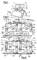
- 15 and 16 show the needle beds of an automatic flat knitting machine, supported, in known manner, by a frame, not illustrated.
- a carriage 5 illustrated diagrammatically in that it is of known type, moves above the needle beds and parallel to them with an outwards and return movement.
- the design includes an electronic control unit (not illustrated in that of known type) which controls the activation and de-activation of the operating units fitted to the carriage for sending the needles into operation, following the instructions in a knitting program.
- an electronic control unit (not illustrated in that of known type) which controls the activation and de-activation of the operating units fitted to the carriage for sending the needles into operation, following the instructions in a knitting program.
- the needle beds 15 and 16 feature, as is known, equidistant slots (not shown in detail in the figure) within which the needles 17 are located.
- the needles 17 are raised (sent into operation) and lowered (returned to the idle position) following a known technique, using further means (not illustrated) such as, for example, sinkers, also located inside the slots, and cams fitted to the carriage 5.
- the needles 17 are sent into operation, in succession, in one or more zones Z, dynamically situated beneath the carriage 5 at each passing of the latter.
- the example illustrated in Figures 2 and 3 features two work zones Z of the needles 17, which are sent into operation by an equal number of operating units located on the carriage.
- a box-shaped element 1 is mounted above the carriage 5 by, for example, two mounting pins 3.
- a plate 10 an integral part of element 1, lies vertically above the needle beds 15 and 16, in a position that is symmetrical to them.
- One side of the plate 10 features a series of grooves 11, laid out in pairs, with the grooves of each pair being located on either side of the operating units, and thus also of the respective work zones Z.
- the grooves 11 have the function of housing and guiding an equal number of pins 12a and 12b such that the latter are able to slide vertically along their axes in opposite directions A and S, being lowered and raised respectively.
- Pins 12a and 12b each make up a pair related to each zone Z, and are in a mutual relationship as described below.
- Each pair of pins features a rocker 20 which is hinged, at its mid point, to the plate 10, in a central position in relation to the pins themselves, such that it is able to swing in opposite directions M and N, lying in a plane parallel to plate 10.
- a third arm 21c located in an upwards position on each rocker, engages with drive means 2.
- the drive means 2 comprise a rod 4 with rack section that is located above the plate 10 and parallel to it, and which is able to be moved along its axis in opposite directions L and R, engaging with a pinion 8 connected to a motor 14 by means of a shaft 9, and featuring two end pieces, 6a and 6b, fitted to its ends.
- the two end pieces 6a and 6b feature seat 7 which are designed to receive the free ends of the abovementioned arms 21c.
- the motor 14, of the step-by-step type is housed inside the box-shaped element 1, from which the shaft 9 protrudes.
- the latter causes the rocker 20 to swing in the same way in direction M, consequently lowering the odd pins 12a in direction A, and at the same time raising the even pins 12b in direction S.
- Stitch-retaining means 24 or stitch-pressing means 22, which can be interchanged according to the requirements of the type of knitting being produced, are fitted so that they are able to be moved, following a known procedure, to the lower ends of pins 12a and 12b.
- the above device enables one to use stitch retaining-pressing means (which can be quickly and easily changed over, substituting the first with the second) on carriages moving in opposite directions.
- a considerable advantage of the invention is the possibility of electronically controlling the raising and lowering of the pins 12a and 12b, in order to activate the stitch retaining and pressing means respectively upstream and downstream of zones Z, by means of signals sent to the motor 14 by the electronic control unit following corresponding instructions contained as required within the knitting programme.
- Instructions in this programme can also be used to control the pressure of the stitch-retaining and pressing means on the fabric, due to the possibility of controlling the step-by-step motor.
- this pressure can be discontinuous, thus giving rise, only on those machines using stitch-pressing means, to an effective hammering action on the fabric, which is excellent for certain special types of knitting.
Landscapes
- Engineering & Computer Science (AREA)
- Textile Engineering (AREA)
- Knitting Machines (AREA)
Claims (2)
Applications Claiming Priority (2)
| Application Number | Priority Date | Filing Date | Title |
|---|---|---|---|
| IT8704961U IT212179Z2 (it) | 1987-10-02 | 1987-10-02 | Apparato per il supporto,il comando ed il controllo di organi pressamaglia-battimaglia in una macchina rettilinea per maglieria |
| IT496187U | 1987-10-02 |
Publications (2)
| Publication Number | Publication Date |
|---|---|
| EP0310565A1 EP0310565A1 (de) | 1989-04-05 |
| EP0310565B1 true EP0310565B1 (de) | 1992-02-19 |
Family
ID=11116481
Family Applications (1)
| Application Number | Title | Priority Date | Filing Date |
|---|---|---|---|
| EP88830288A Expired EP0310565B1 (de) | 1987-10-02 | 1988-07-07 | Vorrichtung zur Halterung, Steuerung and Überwachung von Maschendruck-, Maschenschlagorganen einer Flachstrickmaschine |
Country Status (5)
| Country | Link |
|---|---|
| US (1) | US4852369A (de) |
| EP (1) | EP0310565B1 (de) |
| DE (1) | DE3868476D1 (de) |
| ES (1) | ES2030211T3 (de) |
| IT (1) | IT212179Z2 (de) |
Families Citing this family (9)
| Publication number | Priority date | Publication date | Assignee | Title |
|---|---|---|---|---|
| IT1234090B (it) * | 1989-05-29 | 1992-04-29 | Emm Srl | Apparato per il supporto ed il comando di organi pressamaglia e battimaglia in una macchina rettilinea automatica per maglieria |
| JPH038841A (ja) * | 1989-06-02 | 1991-01-16 | Shima Seiki Seisakusho:Kk | Vベツド横編機における編地プレツサー |
| JPH0672347B2 (ja) * | 1990-08-22 | 1994-09-14 | 株式会社島精機製作所 | 揺動シンカーとプレッサーバーを有する横編機 |
| JP2602156B2 (ja) * | 1992-11-09 | 1997-04-23 | 株式会社島精機製作所 | 横編機の編地プレッサー |
| DE602004032012D1 (de) * | 2003-02-05 | 2011-05-12 | Shima Seiki Mfg | Maschenpresser für eine flachstrickmaschine |
| CN102134780A (zh) * | 2011-04-28 | 2011-07-27 | 浙江丰帆数控机械有限公司 | 针织横机天桥 |
| US9404206B2 (en) * | 2013-02-28 | 2016-08-02 | Nike, Inc. | Feeder for knitting machine having pushing member |
| EP3034665B1 (de) * | 2014-12-18 | 2024-01-24 | KARL MAYER STOLL R&D GmbH | Flachstrickmaschine mit einer Vorrichtung zum Einstreifen und Einlegen von Schuss-, Kett- und/oder Flottfäden |
| US10349702B2 (en) * | 2016-09-09 | 2019-07-16 | Nike, Inc. | Knitting of multiple uppers on a machine |
Family Cites Families (6)
| Publication number | Priority date | Publication date | Assignee | Title |
|---|---|---|---|---|
| CH382361A (de) * | 1961-03-29 | 1964-09-30 | Stamag Ag | Zurückhalte- und Niederleitvorrichtung zum gewichtslosen Abzug der Ware bei Doppelbettstrickapparaten |
| US4501132A (en) * | 1977-11-03 | 1985-02-26 | Courtaulds Plc | Presser foot mechanism in a knitting machine |
| DE3104533C2 (de) * | 1981-02-09 | 1985-07-25 | Universal Maschinenfabrik Dr. Rudolf Schieber GmbH & Co KG, 7081 Westhausen | Flachstrickmaschine mit Einstreicheinrichtung |
| JPS57183451A (en) * | 1981-04-28 | 1982-11-11 | Shima Idea Center | Knitted cloth press apparatus in v bed traverse knitting machine |
| DE3120554C2 (de) * | 1981-05-22 | 1984-01-05 | Universal Maschinenfabrik Dr. Rudolf Schieber GmbH & Co KG, 7081 Westhausen | Flachstrickmaschine mit Einstreicheinrichtung |
| EP0112125B1 (de) * | 1982-12-09 | 1986-03-19 | J. & P. Coats, Limited | Mascheneinstreichervorrichtung zur Anwendung in Zusammenwirkung mit einer Strickmaschine |
-
1987
- 1987-10-02 IT IT8704961U patent/IT212179Z2/it active
-
1988
- 1988-07-06 US US07/215,650 patent/US4852369A/en not_active Expired - Fee Related
- 1988-07-07 DE DE88830288T patent/DE3868476D1/de not_active Expired - Fee Related
- 1988-07-07 EP EP88830288A patent/EP0310565B1/de not_active Expired
- 1988-07-07 ES ES198888830288T patent/ES2030211T3/es not_active Expired - Lifetime
Also Published As
| Publication number | Publication date |
|---|---|
| IT212179Z2 (it) | 1989-07-04 |
| IT8704961V0 (it) | 1987-10-02 |
| ES2030211T3 (es) | 1992-10-16 |
| US4852369A (en) | 1989-08-01 |
| EP0310565A1 (de) | 1989-04-05 |
| DE3868476D1 (en) | 1992-03-26 |
Similar Documents
| Publication | Publication Date | Title |
|---|---|---|
| US5031423A (en) | Pattern control device for flat knitting machines | |
| EP0310565B1 (de) | Vorrichtung zur Halterung, Steuerung and Überwachung von Maschendruck-, Maschenschlagorganen einer Flachstrickmaschine | |
| EP0452018B1 (de) | Vorrichtung zur Einstellung der Maschenlänge auf einer Flachstrickmaschine | |
| US4905483A (en) | Flat knitting machine | |
| JP3463210B2 (ja) | 横編機のカム用移動装置 | |
| US4510775A (en) | Flat knitting machine capable of changing stitch density | |
| EP0597548B1 (de) | Gestrick-Presseinrichtung für Flachstrickmaschine | |
| US2971482A (en) | Automatic zigzag-stitch sewing machine | |
| EP0567282B1 (de) | Flachstrickmachine und Verfahren zum Steuern der Schwingplatinen der Flachstrickmachine | |
| CN111593473A (zh) | 一种横机中的编织三角系统 | |
| KR920008018B1 (ko) | V 베드 횡편기에 있어서의 편지(編地) 프레서 | |
| CN101310057A (zh) | 横机的三角座滑架搭载单元 | |
| KR20020075930A (ko) | 횡편기의 급사장치 | |
| US4660392A (en) | Device for controlling the vertical tension of the knitted fabric in automatic flat knitting machines | |
| US5042273A (en) | Control device for plunger needles in crochet galloon machines | |
| US6125666A (en) | Narrow width crochet knitting machine having driving mechanism of weft guide bar and two or more warp guide bars | |
| US4192156A (en) | Knitting method and apparatus | |
| US4414826A (en) | Summation drive for controlling shogging in a warp knitting machine | |
| US5060488A (en) | Device for supporting and controlling stitch-pressing and stitch-retaining means in an automatic straight knitting machine | |
| US4856298A (en) | Needle actuating device for a circular knitting machine | |
| EP0604164B1 (de) | Verfahren zum Stricken eines Kreuzmusters und Vorrichtung zum Stricken eines Kreuzmusters an einer Flachstrickmachine | |
| GB2112821A (en) | Flat knitting machine | |
| US3220220A (en) | Automatic increasing mechanism in a flat knitting machine | |
| US2233664A (en) | High speed flat knitting machine | |
| US3783643A (en) | Knitting machines having linearly arranged needles |
Legal Events
| Date | Code | Title | Description |
|---|---|---|---|
| PUAI | Public reference made under article 153(3) epc to a published international application that has entered the european phase |
Free format text: ORIGINAL CODE: 0009012 |
|
| AK | Designated contracting states |
Kind code of ref document: A1 Designated state(s): BE CH DE ES FR GB LI |
|
| 17P | Request for examination filed |
Effective date: 19890914 |
|
| 17Q | First examination report despatched |
Effective date: 19910522 |
|
| RAP1 | Party data changed (applicant data changed or rights of an application transferred) |
Owner name: E.M.M.S.R.L. |
|
| RAP3 | Party data changed (applicant data changed or rights of an application transferred) |
Owner name: E.M.M. S.R.L. |
|
| GRAA | (expected) grant |
Free format text: ORIGINAL CODE: 0009210 |
|
| AK | Designated contracting states |
Kind code of ref document: B1 Designated state(s): BE CH DE ES FR GB LI |
|
| REF | Corresponds to: |
Ref document number: 3868476 Country of ref document: DE Date of ref document: 19920326 |
|
| ET | Fr: translation filed | ||
| REG | Reference to a national code |
Ref country code: ES Ref legal event code: FG2A Ref document number: 2030211 Country of ref document: ES Kind code of ref document: T3 |
|
| PLBE | No opposition filed within time limit |
Free format text: ORIGINAL CODE: 0009261 |
|
| STAA | Information on the status of an ep patent application or granted ep patent |
Free format text: STATUS: NO OPPOSITION FILED WITHIN TIME LIMIT |
|
| 26N | No opposition filed | ||
| PGFP | Annual fee paid to national office [announced via postgrant information from national office to epo] |
Ref country code: ES Payment date: 19930705 Year of fee payment: 6 |
|
| PGFP | Annual fee paid to national office [announced via postgrant information from national office to epo] |
Ref country code: GB Payment date: 19930707 Year of fee payment: 6 |
|
| PGFP | Annual fee paid to national office [announced via postgrant information from national office to epo] |
Ref country code: DE Payment date: 19930709 Year of fee payment: 6 Ref country code: BE Payment date: 19930709 Year of fee payment: 6 |
|
| PGFP | Annual fee paid to national office [announced via postgrant information from national office to epo] |
Ref country code: FR Payment date: 19930721 Year of fee payment: 6 |
|
| PGFP | Annual fee paid to national office [announced via postgrant information from national office to epo] |
Ref country code: CH Payment date: 19931027 Year of fee payment: 6 |
|
| PG25 | Lapsed in a contracting state [announced via postgrant information from national office to epo] |
Ref country code: GB Effective date: 19940707 |
|
| PG25 | Lapsed in a contracting state [announced via postgrant information from national office to epo] |
Ref country code: ES Free format text: LAPSE BECAUSE OF EXPIRATION OF PROTECTION Effective date: 19940708 |
|
| PG25 | Lapsed in a contracting state [announced via postgrant information from national office to epo] |
Ref country code: LI Effective date: 19940731 Ref country code: CH Effective date: 19940731 Ref country code: BE Effective date: 19940731 |
|
| BERE | Be: lapsed |
Owner name: E.M.M. S.R.L. Effective date: 19940731 |
|
| GBPC | Gb: european patent ceased through non-payment of renewal fee |
Effective date: 19940707 |
|
| PG25 | Lapsed in a contracting state [announced via postgrant information from national office to epo] |
Ref country code: FR Effective date: 19950331 |
|
| REG | Reference to a national code |
Ref country code: CH Ref legal event code: PL |
|
| PG25 | Lapsed in a contracting state [announced via postgrant information from national office to epo] |
Ref country code: DE Effective date: 19950401 |
|
| REG | Reference to a national code |
Ref country code: FR Ref legal event code: ST |
|
| REG | Reference to a national code |
Ref country code: ES Ref legal event code: FD2A Effective date: 19991001 |