EP0310570A2 - Dispositif de transmission de couple - Google Patents
Dispositif de transmission de couple Download PDFInfo
- Publication number
- EP0310570A2 EP0310570A2 EP88830343A EP88830343A EP0310570A2 EP 0310570 A2 EP0310570 A2 EP 0310570A2 EP 88830343 A EP88830343 A EP 88830343A EP 88830343 A EP88830343 A EP 88830343A EP 0310570 A2 EP0310570 A2 EP 0310570A2
- Authority
- EP
- European Patent Office
- Prior art keywords
- pawls
- core
- shaft
- box according
- mechanical drive
- Prior art date
- Legal status (The legal status is an assumption and is not a legal conclusion. Google has not performed a legal analysis and makes no representation as to the accuracy of the status listed.)
- Withdrawn
Links
- 230000033001 locomotion Effects 0.000 claims abstract description 38
- 230000005540 biological transmission Effects 0.000 claims abstract description 35
- 238000007493 shaping process Methods 0.000 claims abstract description 14
- 230000009471 action Effects 0.000 claims description 21
- 238000006073 displacement reaction Methods 0.000 claims description 20
- 230000008878 coupling Effects 0.000 claims description 17
- 238000010168 coupling process Methods 0.000 claims description 17
- 238000005859 coupling reaction Methods 0.000 claims description 17
- 230000008719 thickening Effects 0.000 claims description 8
- 238000006243 chemical reaction Methods 0.000 claims description 4
- 239000007787 solid Substances 0.000 claims description 4
- 230000003993 interaction Effects 0.000 claims description 3
- 230000014759 maintenance of location Effects 0.000 claims description 3
- 239000010687 lubricating oil Substances 0.000 claims description 2
- 230000000750 progressive effect Effects 0.000 claims description 2
- 238000005096 rolling process Methods 0.000 claims description 2
- 238000011156 evaluation Methods 0.000 claims 1
- 238000005461 lubrication Methods 0.000 description 8
- 239000000314 lubricant Substances 0.000 description 7
- 230000006835 compression Effects 0.000 description 6
- 238000007906 compression Methods 0.000 description 6
- 230000000670 limiting effect Effects 0.000 description 6
- 239000003921 oil Substances 0.000 description 5
- 230000002441 reversible effect Effects 0.000 description 3
- 230000006399 behavior Effects 0.000 description 2
- 238000010276 construction Methods 0.000 description 2
- 230000035515 penetration Effects 0.000 description 2
- 230000002829 reductive effect Effects 0.000 description 2
- 230000000717 retained effect Effects 0.000 description 2
- 230000005489 elastic deformation Effects 0.000 description 1
- 238000009434 installation Methods 0.000 description 1
- 239000000463 material Substances 0.000 description 1
- 230000009347 mechanical transmission Effects 0.000 description 1
- 238000000034 method Methods 0.000 description 1
- 238000005381 potential energy Methods 0.000 description 1
- 230000008569 process Effects 0.000 description 1
- 230000007420 reactivation Effects 0.000 description 1
- 238000009877 rendering Methods 0.000 description 1
- 230000000284 resting effect Effects 0.000 description 1
- 238000007789 sealing Methods 0.000 description 1
- 230000011664 signaling Effects 0.000 description 1
- 125000006850 spacer group Chemical group 0.000 description 1
- 230000002269 spontaneous effect Effects 0.000 description 1
- 230000009466 transformation Effects 0.000 description 1
Images







Classifications
-
- F—MECHANICAL ENGINEERING; LIGHTING; HEATING; WEAPONS; BLASTING
- F16—ENGINEERING ELEMENTS AND UNITS; GENERAL MEASURES FOR PRODUCING AND MAINTAINING EFFECTIVE FUNCTIONING OF MACHINES OR INSTALLATIONS; THERMAL INSULATION IN GENERAL
- F16D—COUPLINGS FOR TRANSMITTING ROTATION; CLUTCHES; BRAKES
- F16D7/00—Slip couplings, e.g. slipping on overload, for absorbing shock
- F16D7/02—Slip couplings, e.g. slipping on overload, for absorbing shock of the friction type
- F16D7/024—Slip couplings, e.g. slipping on overload, for absorbing shock of the friction type with axially applied torque limiting friction surfaces
- F16D7/028—Slip couplings, e.g. slipping on overload, for absorbing shock of the friction type with axially applied torque limiting friction surfaces with conical friction surfaces
-
- F—MECHANICAL ENGINEERING; LIGHTING; HEATING; WEAPONS; BLASTING
- F16—ENGINEERING ELEMENTS AND UNITS; GENERAL MEASURES FOR PRODUCING AND MAINTAINING EFFECTIVE FUNCTIONING OF MACHINES OR INSTALLATIONS; THERMAL INSULATION IN GENERAL
- F16D—COUPLINGS FOR TRANSMITTING ROTATION; CLUTCHES; BRAKES
- F16D11/00—Clutches in which the members have interengaging parts
- F16D11/08—Clutches in which the members have interengaging parts actuated by moving a non-rotating part axially
- F16D11/12—Clutches in which the members have interengaging parts actuated by moving a non-rotating part axially with clutching members movable otherwise than only axially
-
- F—MECHANICAL ENGINEERING; LIGHTING; HEATING; WEAPONS; BLASTING
- F16—ENGINEERING ELEMENTS AND UNITS; GENERAL MEASURES FOR PRODUCING AND MAINTAINING EFFECTIVE FUNCTIONING OF MACHINES OR INSTALLATIONS; THERMAL INSULATION IN GENERAL
- F16D—COUPLINGS FOR TRANSMITTING ROTATION; CLUTCHES; BRAKES
- F16D11/00—Clutches in which the members have interengaging parts
- F16D11/16—Clutches in which the members have interengaging parts with clutching members movable otherwise than only axially
-
- F—MECHANICAL ENGINEERING; LIGHTING; HEATING; WEAPONS; BLASTING
- F16—ENGINEERING ELEMENTS AND UNITS; GENERAL MEASURES FOR PRODUCING AND MAINTAINING EFFECTIVE FUNCTIONING OF MACHINES OR INSTALLATIONS; THERMAL INSULATION IN GENERAL
- F16D—COUPLINGS FOR TRANSMITTING ROTATION; CLUTCHES; BRAKES
- F16D25/00—Fluid-actuated clutches
- F16D25/08—Fluid-actuated clutches with fluid-actuated member not rotating with a clutching member
- F16D25/082—Fluid-actuated clutches with fluid-actuated member not rotating with a clutching member the line of action of the fluid-actuated members co-inciding with the axis of rotation
- F16D25/086—Fluid-actuated clutches with fluid-actuated member not rotating with a clutching member the line of action of the fluid-actuated members co-inciding with the axis of rotation the clutch being actuated by a push rod extending coaxially through the input or output shaft
-
- F—MECHANICAL ENGINEERING; LIGHTING; HEATING; WEAPONS; BLASTING
- F16—ENGINEERING ELEMENTS AND UNITS; GENERAL MEASURES FOR PRODUCING AND MAINTAINING EFFECTIVE FUNCTIONING OF MACHINES OR INSTALLATIONS; THERMAL INSULATION IN GENERAL
- F16D—COUPLINGS FOR TRANSMITTING ROTATION; CLUTCHES; BRAKES
- F16D41/00—Freewheels or freewheel clutches
- F16D41/18—Freewheels or freewheel clutches with non-hinged detent
-
- F—MECHANICAL ENGINEERING; LIGHTING; HEATING; WEAPONS; BLASTING
- F16—ENGINEERING ELEMENTS AND UNITS; GENERAL MEASURES FOR PRODUCING AND MAINTAINING EFFECTIVE FUNCTIONING OF MACHINES OR INSTALLATIONS; THERMAL INSULATION IN GENERAL
- F16D—COUPLINGS FOR TRANSMITTING ROTATION; CLUTCHES; BRAKES
- F16D43/00—Automatic clutches
- F16D43/02—Automatic clutches actuated entirely mechanically
- F16D43/20—Automatic clutches actuated entirely mechanically controlled by torque, e.g. overload-release clutches, slip-clutches with means by which torque varies the clutching pressure
- F16D43/202—Automatic clutches actuated entirely mechanically controlled by torque, e.g. overload-release clutches, slip-clutches with means by which torque varies the clutching pressure of the ratchet type
- F16D43/2028—Automatic clutches actuated entirely mechanically controlled by torque, e.g. overload-release clutches, slip-clutches with means by which torque varies the clutching pressure of the ratchet type with at least one part moving radially between engagement and disengagement
-
- Y—GENERAL TAGGING OF NEW TECHNOLOGICAL DEVELOPMENTS; GENERAL TAGGING OF CROSS-SECTIONAL TECHNOLOGIES SPANNING OVER SEVERAL SECTIONS OF THE IPC; TECHNICAL SUBJECTS COVERED BY FORMER USPC CROSS-REFERENCE ART COLLECTIONS [XRACs] AND DIGESTS
- Y10—TECHNICAL SUBJECTS COVERED BY FORMER USPC
- Y10T—TECHNICAL SUBJECTS COVERED BY FORMER US CLASSIFICATION
- Y10T74/00—Machine element or mechanism
- Y10T74/19—Gearing
- Y10T74/19642—Directly cooperating gears
- Y10T74/1966—Intersecting axes
- Y10T74/19665—Bevel gear type
Definitions
- the invention relates to oil-bath drive boxes, with input and output shafts. Boxes of this type are currently used in various applications such as agricultural and industrial machines and in fixed and mobile installations. They usually allow only simple gear drives, with cylindrical or conical gears, between parallel or angled shafts.
- the drives on which the above mentioned boxes are used require often further devices - such as engagement and disengagement devices torque limiting devices unidirectional couplings (i.e. freewheels) , flexible couplings, spontaneous or driven slip clutches, and other - which are usually autonomously inserted within the drive.
- torque limiting devices unidirectional couplings (i.e. freewheels)
- flexible couplings i.e. freewheels
- spontaneous or driven slip clutches i.e. freewheels
- other - which are usually autonomously inserted within the drive.
- the object of the invention is to eliminate these drawbacks.
- a mechanical drive box according to the invention having at least a shaft and at least a drive member on the shaft, and a device for the transmission of motion between the shaft and the drive member - is provided in such a way that said device, for the transmission of motion between said shaft and the member mounted thereon, comprises: - a set of pawls radially movable within seats formed in the shaft and on a possible element solid thereto to ensure the pawls guide, said pawls having internal and external ends shaped in radial and/or axial direction; - inside said drive member, a housing; - inside said housing, a drive member having a shaped surface for cooperating with the external ends of said pawls; - inside the shaft, an axial cavity for receiving a shaped and axially movable core for the operation, with elastic means reacting to the axial movement of said core; and - on said core, shapings and inclined surfaces able to cooperate with the internal shaped ends of the pawls;
- a housing may be formed in correspondence of the pawls, and in said housing shaped seats are then perimetrally formed to cooperate with the external shaped ends of the pawls.
- a mechanical drive box may comprise at least two shafts - an input shaft and an output shaft - and at least a gear drive member on one of said shafts; the housing for receiving, at least partially, the device with pawls may thus be formed in the body of said gear.
- the gear is a bevel gear
- the housing is advantageously formed in the larger part of its body.
- radial passages may be provided between the teeth of the gear and as far as the axial cavity of the shaft, with a manifold provided in the cooperating surfaces of said member and shaft.
- the spring means may be held within the cavity and made to rest on a retaining and supporting disc, said ring or disc being possibly provided with means for the retention of lubricating oil.
- a mechanical drive box with input and output shafts and with gears thereon may be provided in the body of each of these gears with a different device having relevant pawls and a relevant core.
- Each of the above mentioned devices may be, for example, a disengaging device and/or a clutch or other, with axial control inside the shaft, respectively, a torque limiting device, or a flexible coupling or other.
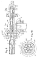
- numeral 1 indicates one of the shafts of the drive and numeral 3 indicates the other shaft orthogonal to the previous one.
- Numerals 5 and 7 indicate the bearings which support the shaft 1 within a drive box 8.
- Numeral 9 indicates one of the bearings which supports the shaft 3.
- Numerals 10 and 12 indicate the two bevel gears that are mounted on shaft 1 and on shaft 3, respectively, for the transmission between said two shafts. Gear 12 is keyed on shaft 3, while gear 10 is coupled to shaft 1 through the illustrated disengaging device.
- Shaft 1 has a deep axial cavity 14 which is tapered towards the left end (looking at the drawing) , and from which a plurality of radial seats 16, formed within an annular expansion 1A of shaft 1, branch off.
- This annular expansion 1A results at least partially received into a housing.20 formed in the wider part of the core of gear 10, that is, in correspondence of the major base of said frustoconical core of the gear. Said gear results engaged between the expansion 1A and a retaining ring 22 with a limited play possibility for a relative rotation with respect to the shaft. Expansion 1A results in abutment against bearing 5.
- Housing 20 exhibits an at right angles profile in its diametral cross section and has a substantially cylindrical perimetral wall, wherein a plurality if seats 24 with at least an inclined profile are formed. In the drawing, seats 24 are shown which are substantially symmetrical with respect to the corresponding pitch diameter.
- the number of seats 24 corresponds at least to the number of radial seats 16 within the annular expansion 1A of shaft 1, all seats being symmetrically distributed.
- radially sliding pawls 26 are housed, which are shaped at their outer end 26A with a shaping corresponding to that of seats 24 with which they must cooperate.
- the pawls inner ends are shaped with two inclined planes 26B and 26C, plane 26B being less inclined than plane 26C with respect to the shaft axis.
- a core 30 is movable with which an axial control rod 32 is solid that projects beyond the end of shaft 1 by going through a seal disc 34 preventing leak of lubricant.
- the seal disc 34 is held by elastic retaining rings.
- Core 30 is urged by a helical spring 36, reacting on the bottom of cavity 14 of shaft 1, in the direction of arrow f36, that is, in such a direction as to cause the control rod 32 to come out from disc 34.
- Core 30 has overall cylindrical dimensions delimited by the two cylindrical end zones 30A and 30B, which allow a correct sliding of the core inside the axial cavity 14, that is also cylindrical at least in the zone where said core must slide.
- the core In the vicinity of the cylindrical zone 30B the core further exhibits a portion with a conical shaping or with flats 40 inclined with respect to the core axis to an extent corresponding to that of the pawls surfaces 26B having less inclination.
- This portion is followed by a zone 42 which may be frustoconical or have flats lined up with those indicated by 40 but having greater inclination with respect to the core axis, corresponding to the inclination of surfaces 26C of pawls 26.
- an annular groove 44 is thereby created having such a width as to be able to house the inner ends of the pawls.
- the lower inclination of surfaces 26B and surfaces 40 may correspond to the inclination of the cone or angle of friction between surfaces 26B and 40 in the lubrication conditions provided inside cavity 14 for the purposes to be indicated.
- the lubrication inside cavity 14 and thus inside the disengaging device is ensured through the motion of gear 10, by the presence of radial holes 46 in correspondence of the slot between adjacent teeth of gear 10, through an annular manifold 47 and corresponding holes 48 suitably distributed in the thickness of shaft 1 between the outside and cavity 14, over the core sliding zone.
- the core 30 may exhibit, in place of surfaces 40, a frustoconical or a cylindrical surface, or even a prismatic configuration.
- spring 36 urges the pawls through the surfaces 42 and 26C to expand in centrifugal direction so that same pawls penetrate again into the seats 24 with a limited relative angular movement between gear 10 and shaft 1, especially at the moment in which the displacement is made to begin and, however, when the seats 24 are in front of the pawls.
- the configuration of the inner ends of pawls and of core 30 allows to obtain a manoeuvre to be made through a very short run of the central core.
- the manoeuvre is interrupted by the penetration of pawls 26 into groove 44, owing to the presence of the stop provided by the central core on one side of said groove 44.
- Spring 36 which acts axially on the core, gives stability to the device in its condition of motion transmission and counteracts (by a force predetermined through the calibration of spring 36) the disengagement manoeuvre by rendering such manoeuvre “sensitive” and allows as well the automatic reactivation of the engagement device as soon as the external thrust on control rod 32 has stopped.
- the disengaging manoeuvre obtained by the thrust according to arrow f32 on the control rod 32, must be broken off only after stopping or greatly slowing down the velocity of all the moving parts.
- the device has very limited overall dimensions, so that it can be held in the same drive box provided for the transmission between shafts 1 and 3 as in the traditional transmissions.
- Rod 132 is no longer driven in the direction of arrow f32 but in the direction of arrow f132 that is through a tensile action, and for this purpose, a control member 146 is provided, which is combined with rod 132 through a rolling bearing 148 in such a way that, by maintaining the tensile action on member 146 according to arrow f132, the action of spring 136 is won and the engagement condition of the device with pawls 26 coupled to gear 10 is obtained. By stopping the tensile action on the control member 146, the action of spring 136 is allowed, which causes the core 130 to be pushed so as to present the groove 44 in correspondence of the pawls which are centripetally pushed by the profiles of seats 24 for the disengagement.
- the engagement takes place by exerting a pull on member 146 sufficient to bring back the pawls, through the inclined surfaces 42 and 26C with a centrifugal motion, as far as to fit into seats 24 in order to give rise again to the motion transmission. Also in this case the limited inclination of surfaces 40, to an extent corresponding to the angle of friction, allows rod 132 and spring 136 to be operated without any particular dependence of the transmitted load and thus of the pawls pressure upon core 30.
- Spring 136 is made to abut on same disc 34 as already provided in the previously disclosed arrangement, which disc in this case has both the function of providing a seal for the lubricant and a reaction support for spring 136.
- Figs.13 to 20 show an embodiment of a torque limiting device combined with a gear drive inside a drive box.
- Numerals 201 and 203 indicate two shafts, orthogonal to one another, between which the motion must be transmitted through the above mentioned torque limiting device.
- Numerals 205 and 207 indicate the bearings for the assembling of shaft 201, while numeral 209 indicates one of the bearings of shaft 203.
- the mechanical transmission between said two shafts takes place by means of a pair of bevel gears 210 and 212.
- a torque limiting device is predisposed between gear 210 and shaft 201.
- an axial cavity 214 is formed, starting from the right end of the shaft, looking at the drawing.
- a core 216 is inserted, which core is shaped with a plurality of uniformly distributed, inclined surfaces 218. Beyond the edge of each surface 218 which is closer to the core axis, a surface 220 - especially a conical surface - is provided, heavily inclined with respect to the core axis, followed by an extension 222 having cross-section corresponding to the one on zones 218, or having a frustoconical shape, at the most.
- the predetermined, relative angular position of core 216 must be maintained.
- a coaxial rod 224 is engaged, extending up to the outside of cavity 214.
- This rod 224 is screwed on a cylindrical extension 216A having reduced cross-section and being opposite to the extension 222.
- Rod 224 goes through a disc 226 which is engaged through an elastic expansion ring 228 with the internal wall of cavity 214, towards the open end of this cavity.
- spring means are provided in the form of two helical springs 230 and 232 (in the drawing) which rest on core 216, 216A and on disc 226 for exerting a compression through a thrust that can be set according to the maximum torque transmittable by means of the device.
- the setting of this maximum torque can be achieved by replacing either or both springs and also by interposing shims of suitable sizes between the spring(s) and disc 226.
- a plurality of radial seats 234 are formed within an annular expansion 201A of shaft 20i for slidingly receiving a corresponding number of radial pawls 236 each of which corresponds to a surface 218.
- the inner ends of pawls 236 have a surface 236A inclined like the surfaces 218, another surface 236B inclined like the surface 220 and a third surface 236C forming a step.
- the outer end of each pawl is shaped with a suitable, symmetric or non symmetric profile 236D.
- the body of gear 210 exibits a housing 240 with a cylindrical coaxial wall, wherein seats 242 are formed having side profiles inclined symmetrically and in correspondence to the shaping 236D of the outer ends of pawls 236.
- seats 242 are formed having side profiles inclined symmetrically and in correspondence to the shaping 236D of the outer ends of pawls 236.
- the annular expansion 20lA of shaft 201 is partially received, while pawls 236, being in a centrifugally displaced arrangement within the radial seats 234, are received into seats 242.
- the core 216 urged by springs 230, 232 comes into contact through its surfaces 218, with the surfaces 236A of pawls 236, thereby causing them to take the centrifugally displaced position with the ends 236D within the seats 242.
- the torque is transmitted between shaft 201 and gear 210, one of these two members being the driving member and the other the driven one.
- the balance is maintained between the radial thrust transmitted by the inclined surfaces of seats 242 and ends 236D, and the thrust transmitted by the elastic means 230, 232 through the core and the inclined surfaces 218,. 236A.
- Rod 224 has the function of providing information about the instantaneous engaged or disengaged condition of the device through the position taken up by the outer end of same rod. It is thus possible to obtain a warning signal or a command by gathering a message from the rod displacement. This message may also imply a warning before the disengagement.
- the guiding of body 216 may be ensured by a suitable conformation of the same body to cooperate with the surface of hole 214 (instead by the intervention of the rod).
- the lubricant is made to enter the cavity 214 through holes 250 in the gear body, an annular manifold 252 in the shaft and radial holes 254 between the manifold and same cavity 214.
- Pawls 262 (similar to those indicated by 236) have their outer ends modified, with two inclined surfaces 262A and 262B parallel to each other, and a less inclined surface 262C.
- Seats 264 (operatively equivalent to those indicated by 242) are correspondingly defined by inclined surfaces having the same inclination as surfaces 2G2A and 262B and almost the same interspace.
- the limiting device operates only in one direction of rotation: In the direction of arrow f201 if the shaft acts as a driving member, and in the opposite direction if the gear is the driving member. The re-engagement takes place at very low speed and in dependence of the inclination of surfaces 262C. In some cases, the device may function also as a freewheel.
- Figs.23 to 30 show a mechanical drive realization with a unidirectional, that is, freewheel transmission device, that may be held inside a drive box for the transmission, for example, between shafts orthogonal to each other.
- Numeral 301 indicates one of the two shafts and numeral 303 the other shaft orthogonal to the previous one.
- Shaft 301 is mounted with bearings 305 and 307, while numeral 309 indicates one of the bearings of shaft 303.
- a bevel gear 310 is keyed, which meshes with a bevel gear 312 mounted on shaft 301 to rotate freely thereon, but also to be coupled thereto through the frewheel device to be described.
- Gear 312 is retained between an annular thickening 301A of shaft 301 and an elastic ring mounted in an annular groove of same shaft. Gear 312 is capable of rotating with respect to shaft 301 but is prevented from performing relative axial displacements.
- the wider part of the frustoconical body of bevel gear 312 has a cylindrical wall housing 316, which is apt to receive, at least partially, the thickening 301A of shaft 301.
- seats 318 are formed being shaped with a portion of inclined profile 318A and with an arcuate end portion 318B, the latter having a surface, at least radially disposed, or even with a counterslope in the same direction of the inclination of surface 318A but with an angle (relative to the radial direction) far lower than that of the same surface 318A.
- Seats 318 are circumferentially distributed in a symmetrical manner, corresponding to the distribution and number of seats 318 and radial cylindrical through seats 320 are formed in the thickening 301A, mostly for a corresponding number of radial pawls 322 able to slide in respective seats 320.
- each pawl 322 has a surface 322A with an inclination corresponding, at least partially, to that of surface 318A in the seats 318 and with a step-like shaping which matches, at least partially, the portion 318B of seats 318.
- the inner end of each pawl 322 has a frustoconical shaping 322C and an inclined flat 322E.
- the pawls outer ends 322A, 322B are able to cooperate with the side surface of the housing 316 and with the seats 318, while the pawls inner ends 322C project within an axial cavity 324 which is formed in the shaft 301 starting from the right end thereof (looking at the drawing).
- a core 326 is housed that is capable of sliding within same cavity and is urged towards the left side (looking at the drawing) by a spring 328, which operates a compression between the core 326 and a disc 330 mounted at ths end of shaft 301 with a retaining means such as an elastic ring or the like.
- Core 326 has a cylindrical portion for the guided sliding and a frustoconical portion 326A, whose inclination substantially corresponds to the inclination of the flats 322E of pawls 322 which, thereofore, are resting on the frustoconical surface of portion 326A, each one along one line.
- the shaft 301 being considered the driving member, is able to transmit the motion to gear 312 according to arrow f301, while a reverse displacement of shaft 301 does not transmit the motion to gear 312.
- a movement of gear 312 according to arrow f301, relative to shaft 301 is not followed by a corresponding movement of same shaft 301.
- spring 328 tends to urge the pawls into engagement and thus to cause the coupling for a drive according to f301 of gear 312 through shaft 301, respectively for a drive of shaft 301 through gear 312 in a direction opposite to arrow f301.
- said pawls 322 tend to be urged in centripetal direction against surface 326A and cause the elastic yielding of core 326 in the axial direction against the action of springs 328, in order to allow the pawl skipping with respect to the seats 318.
- the described freewheel device is efficiently lubricated within a box containing gears 310, 312 dipped in oil bath, by providing a circulation system which includes a hole or a set of holes 334 in the body of gear 312 in correspondence of the slot between adjacent teeth.
- a manifold 336 and one or several holes 338 leading to the cavity 324 correspond on shaft 301 to ensure both the lubrication of the core which must slide within the axial cavity 324 and of the pawls 322 which have to slide with respect to the surface 326A of core 326, and of the seats 320 provided for these pawls.
- Figs.31 to 38 show a drive device operating like a flexible coupling or spring drive to allow limited relative angular movements of elastic type between the transmission members.
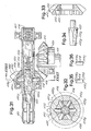
- Numerals 401 and 403 indicate the two shafts between which a drive comprising said flexible coupling is interposed, the two shafts being orthogonal to each other.
- Numerals 405 and 407 indicate the bearings for the support of shaft 401, while numeral 409 indicates one of the bearings of shaft 403.
- the transmission is operated through two bevel gears 410 and 412, mounted on shaft 401 and shaft 403 respectively.
- Gear 412 is keyed on said shaft 403, while gear 410 is combined to the shaft 401 through the flexible coupling device to be described.
- the drive with the flexible coupling may be housed in a drive box from which the two shafts 401 and 403 project, the drive box being of oil bath type.
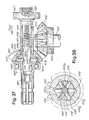
- Shaft 401 exhibits a deep axial cavity 414, which starts from the right end (looking at the drawing) of said shaft.
- Shaft 401 has also an annular thickening 401A, in correspondence of which radial seats 416 are formed for as many sliding pawls 418.
- Each pawl 418 has the outer end 418A shaped with inclined surfaces.
- the inner end of each pawl 418 has an inclined surface 418B and a portion of surface 418C of zero inclination, that is, perpendicular to the pawl axis.
- a core 420 slides with a cylindrical part for the guided sliding thereof inside said cavity 414 and with a plurality of flat surfaces 420A which are inclined according to the same inclination as surfaces 418B.
- the angle of inclination of surfaces 420A with respect to the core and the axis of shaft 401 is significantly greater than the angle of friction relative to the surface 418B of each pawl 418 and to the corresponding surface 420A of core 420, under the lubrication conditions to which the same surfaces are subjected.
- Core 420 ends with stretches of surface 420B having zero inclination with respect to the axis of shaft 401 and of core 420 in the portion of said core having smaller cross-section.
- Core 420 is urged according to arrow f420 by a spring assembly 422 and 424 which react between said core 420 and a disc 426 mounted inside cavity 414 in the vicinity of the end axial opening of said cavity 414.
- the arrangement of pawls 418 and flats 420B of core 420 is symmetrical with respect to the axis of shaft 401.
- the bevel gear 410 has, in the wider part of its frustoconical body, a circular housing 430 partially receiving the thickening 401A of shaft 401.
- the housing 430 has a cylindrical perimetral wall in which seats 432 are formed having a profile corresponding to that of the outer ends 418A of pawls 418.
- the number and disposition of seats 432 correspond to those of the pawls.
- the seats 432 and the outer ends of pawls 418A have their surfaces correspondingly inclined and jointed. Said surfaces are relatively long.
- the gear 410 is fitted on shaft 401 and is slidingly engaged thereto between the thickening 401A and an elastic retaining ring 434, mounted in a groove provided in said shaft.
- gear 410 is free to rotate relative to shaft 401 but is engaged through the pawls in the manner described below.
- the seats 432 and the outer ends 418A of pawls 418 may have the surfaces inclined in a symmetrical way (as in the drawing) or in asymmetrical way, in order to have the same behaviour in the two directions of rotation, or different behaviours in one direction and in the opposite direction of rotation. It is even possible to have only one of the surfaces inclined.
- the lubrication of members inside the cavity 414 and in particular of pawls 418 and core 420 is achieved by providing one or more radial holes 436 within the cavity between adjacent teeth of gear 410, which holes lead into an annular manifold 437 bored in the outer surface of shaft 401 in correspondence of said holes 436 and in correspondence also of one or more radial holes 438 bored in the shaft 401 between said manifold and cavity 414.
- the lubricant may be pushed into the cavity 414 to lubricate the surfaces in relative motion to each other.
- the axial elastic thrust exerted by the suitably calibrated springs 422, 424 on core 420 causes a radial centrifugal thrust on all the pawls 418 because of the interaction between surfaces 420A and surfaces 418B.
- the outer ends of pawls 418 are housed inside the seats 432 in the cylindrical perimetral wall of housing 430 formed in the body of gear 410.
- the transmitted torque generates, on the outer end 418A of pawls 418, a centripetal thrust on same pawls 418 and thus a pressure of surfaces 418B onto the inclined surfaces 420A of core 420, thereby determining an axial thrust on core 420 opposite to that exerted by springs 422 and 424.
- To each value of the transmitted torque there is a corresponding value of said thrust exerted by pawls 418 on core 420, and thus there is a precise balance position of said core 420 resulting from the action of radial pawls 418 and from the thrust of the reaction springs 422, 424.
- An increase of the transmitted torque gives rise to a displacement of the central core 420 with a further compression of springs 422 and 424 and the opposite occurs, with a decrease of said transmission torque.
- pawls 418 remain always engaged in their seats 432, thus ensuring the motion transmission, but come into con act with more or less extended zones of the inclined surfaces of the respective seats 432, anyway over extents being mechanically sufficient to transmit the torque.
- the calibration of springs 422 and 424 may be obtained by replacing springs and also by providing suitable shims between springs and disc 426.
- Disc 426 has also a sealing function for retaining the lubricant within cavity 414.
- Figs.31 and 32 show the normal transmission condition of the described flexible coupling
- Figs.37 and 38 show the condition of the flexible coupling upon reaching the maximum elastic deformation of the springs and thus with the maximum angular elastic yielding in the motion transmission between the two shafts 401 and 403.
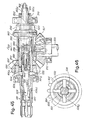
- Figs.39 to 46 show a clutch device provided inside a drive for the transmission between two shafts 501 and 503 at right angles to one another, and between which a motion transmission is provided by two bevel gears 505 and 507, the gear 507 being keyed on shaft 503 and the gear 505 being idly mounted on shaft 501 and able to be connected to and disconnected from same shaft 501 through the clutch device to be described.
- Numerals 509 and 510 indicate two bearings for shaft 501, and numeral 512 indicates one of the bearings for shaft 503.
- the drive box may be of oil bath type like the clutch device to be described.
- Shaft 501 exhibits a deep axial cavity 520, stemming from its right end, looking at the drawing.
- the shaft 501 has also an outer annular thickening 501A in correspondence of which radial seats 522 are partially dug, said seats extending between cavity 520 and the outside, and slidingly receiving a corresponding number of pawls 524.
- Both seats 522 and pawls 524 have rectangular cross-section, particularly a square cross-section.
- Each pawl 524 is provided with an outer flat, inclined surface 524A to cause a strong axial thrust with a displacement of pawl within the seat 522 provided for same pawl.
- each pawl has an inclined surface 524B, whose inclination to the axis of shaft 501 is remarkably greater than the angle of friction occurring between the surface 524B and the cooperating surfaces 526A of a core 526, that is axially sliding within cavity 520.
- core 526 has four flat surfaces 526A inclined to the axis of the shaft with the same inclinations of the pawls inner ends 524B, and also pawls 524 are in number of four, regularly distributed around the shaft axis.
- gear 505 is provided with a wide frustoconical cavity 505A, in which a clutch, i.e. a friction cone 530 may be housed cooperating therewith, said cone being capable of short axial slidings with respect to gear 505 whose axial position is delimited in the manner to be described below.
- the clutch cone 530 has a plurality of radial seats in the form of channels corresponding to the number of pawls and partially accommodating said pawls.
- Seats 532 have a rectangular cross-section and the bottom inclined in correspondence of the inclination of the surfaces 524A of pawls 524.
- a torque is easily transmitted between the shaft 501 and the clutch cone 530 thanks to the rectangular and especially square shape of the cross-section of pawls 524 and the corresponding shape of seats 522 of shaft 501 and of seats 532 of clutch cone 530.
- Gear 505 which is free to rotate with respect to shaft 501, is engaged to the same shaft in axial direction through a system of shoulders which comprise, in particular, a thrust bearing. More particularly, gear 505 is retained between the clutch cone 530 and a spacer 538 which rests on a thrust bearing 540. The position of said bearing 540 is suitably adjusted through a threaded ring 542 which engages in a threading of shaft 501.
- a self-locking elastic ring 536 mounted in a groove of shaft 501, is intended to facilitate the adjustment of bearing 540 by the screw ring 402, so as to ensure the proper postion of gear 505 with respect to gear 507.
- the lubrication of cavity 505A and of the clutch cone is ensured through one or more holes 544 extending between cavity 505A and the slot between adjacent teeth of gear 505.
- pawls 524 and of seats 532 as well as of seats 522 is squared, so that an optimal driving capacity of the clutch cone is obtained by the shaft 501 through the pawls, or vice versa, by the clutch cone to the shaft.
- the inclination with respect to shaft 501, according to which the surfaces 526A of core 526 and the surfaces 524B of pawls 524 are made to coact, is significantly greater than the angle of friction relative to the contacting materials and to the lubrication conditions of these surfaces.
- the central core 526 is elastically urged according to arrow f526 in axial direction by elastic means to be described, and therefore it exerts a centrifugal component on the foot 524B of the pawls according to the axis thereof in a radial direction, which tends to displace same pawls outwardly.
- This component owing to the inclined plane 524A of the pawls and to the inclined surface of the bottom of seats 532 of the clutch cone 530, causes a strong axial thrust of the clutch cone 530 towards the conical wall of cavity 505A formed in the gear 505. This thrust is relevant to obtain the transmission of the friction torque and thus of the clutch-operated torque between members 530 and 505.
- the axial thrust on the central core 526 is determined by a pack of cup-shaped springs 550, which are housed in the cavity 520 and which abut on one side on core 526 and on the other on a threaded sleeve 552 which is engaged with and axially adjustable on an inner threading 520A of cavity 520.
- the springs 550 of the pack of cup-shaped springs are of a type peculiarly capable of maintaining a substantially constant thrust in a definite deflection field and as long as they work within a range of predetermined minimum and maximum heights.
- the calibration is achieved through the axial adjustment of sleeve 552 by means of threadings.
- the sleeve 552 has an axial handling appendix 552A extending outside shaft 501, and a suitable seal gasket 556 operates between the end of shaft 501 (that is, the end of cavity 520) and said extension 552A of sleeve 552 for the seal of the lubricant.
- the sleeve 552 is adjusted to restore the working and calibration conditions.
- the wear conditions of the friction surfaces of the clutch cone 530 and of its surface 505A may be made evident by the presence of a stick 558 engaged to the core 526 and extending into an axial through hole of sleeve 552 and of its extension 552A to project therefrom and be visible.
- a stick 558 engaged to the core 526 and extending into an axial through hole of sleeve 552 and of its extension 552A to project therefrom and be visible.
- the stick 558 may also be provided with one or more fiducial marks like those of a scale.
- the clutch device can be controlled for the disengagement by acting axially on the core against the action of springs 550 to determine the disengagement. It is also conceivable to displace all the assembly made up of core, springs and sleeve, between an engagement position and a disengagement position.
- the inclinations of the cooperating surfaces allow to dispose of a strong thrust of the clutch cone 530, even with a very limited push on the core 526 in axial direction.
- the sleeve 552 has an extension 552B similar to that 552A, but making up a support for a cylinder 570 of a fluid-operated system whose piston 572 is solid with a stem 568 which (like the one indicated by 558) goes through the sleeve 552 and its extension 552B and is engaged to the core 526.
- This stem 568 (instead of having signalling function similarly to stem 558) is intended to drive the core 526 through the cylinder-piston system 570, 572 against the action of springs 550 in order to disengage the clutch cone 530 from its seat within gear 505.
- each of the above described devices is capable of being received into a very limited space and thus contained even in a drive box from which two shafts project and whose dimensions correspond in practice to those of a drive box comprising only the bevel gears like those indicated by 505, 507.
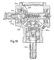
- Fig.51 shows a drive box 600 wherein two shafts 602 and 604 disposed at right angles penetrate. On each of the two shafts, a bevel gear is mounted, respectively indicated by 606 and 608, the two gears cooperating with one another. Between shaft 604 and gear 608 a device generally indicated by 610 is provided, having pawls 610A and core 610B of one of the two types previously described. Between shaft 602 and gear 606, another device is provided, generally indicated by 612, with pawls 612A and core 612B of another of the types previously described. The device 612 may have a manoeuvring or control rod 614.
Landscapes
- Engineering & Computer Science (AREA)
- General Engineering & Computer Science (AREA)
- Mechanical Engineering (AREA)
- Structure Of Transmissions (AREA)
- Friction Gearing (AREA)
Applications Claiming Priority (2)
| Application Number | Priority Date | Filing Date | Title |
|---|---|---|---|
| IT945887 | 1987-08-13 | ||
| IT8709458A IT1229584B (it) | 1987-08-13 | 1987-08-13 | Scatola di trasmissione meccanica a bagno d'olio con alberi d'ingressoe di uscita e con congegni automatici e/o comandati accolti in essa edinseriti nella trasmissione |
Publications (2)
| Publication Number | Publication Date |
|---|---|
| EP0310570A2 true EP0310570A2 (fr) | 1989-04-05 |
| EP0310570A3 EP0310570A3 (fr) | 1989-05-03 |
Family
ID=11130439
Family Applications (1)
| Application Number | Title | Priority Date | Filing Date |
|---|---|---|---|
| EP88830343A Withdrawn EP0310570A3 (fr) | 1987-08-13 | 1988-08-12 | Dispositif de transmission de couple |
Country Status (3)
| Country | Link |
|---|---|
| US (1) | US4919244A (fr) |
| EP (1) | EP0310570A3 (fr) |
| IT (1) | IT1229584B (fr) |
Cited By (3)
| Publication number | Priority date | Publication date | Assignee | Title |
|---|---|---|---|---|
| FR2686855A1 (fr) * | 1992-02-03 | 1993-08-06 | Messier Bugatti | Actionneur lineaire, notamment pour la manóoeuvre d'une jambe d'atterrisseur d'avion. |
| EP1260753A3 (fr) * | 2001-05-23 | 2004-11-10 | Comer Industries S.p.A. | Limiteur de couple à dispositif de découplage de sécurité commandé, en particulier pour prises de force de machines agricoles |
| WO2009049581A1 (fr) * | 2007-10-15 | 2009-04-23 | Luk Lamellen Und Kupplungsbau Beteiligungs Kg | Cylindre récepteur et système de débrayage |
Families Citing this family (9)
| Publication number | Priority date | Publication date | Assignee | Title |
|---|---|---|---|---|
| DE4137829C2 (de) * | 1991-11-16 | 1995-12-21 | Walterscheid Gmbh Gkn | Drehmomentbegrenzungskupplung |
| US5450714A (en) * | 1994-10-07 | 1995-09-19 | Allied Products Corporation | Rotary cutter with counterrotation gearbox |
| US5669213A (en) * | 1995-11-03 | 1997-09-23 | Allied Products Corporation | Counterrotation mulching mower |
| US5809765A (en) * | 1997-03-17 | 1998-09-22 | Allied Products Corporation | Counterrotation mulching mower and blade assembly |
| DE19744154C2 (de) * | 1997-10-07 | 2000-07-06 | Walterscheid Gmbh Gkn | Drehmomentbegrenzungskupplung für einen Antriebsstrang zum Antrieb landwirtschaftlicher Geräte |
| US6308588B1 (en) * | 1999-09-09 | 2001-10-30 | Gkn Walterscheid Gmbh | Angle drive having an integrated coupling with rotational play |
| US20090260468A1 (en) * | 2005-08-31 | 2009-10-22 | Thk Co., Ltd. | Steering device and movement converting device used therefor |
| NL1039622C2 (nl) * | 2012-05-23 | 2013-11-26 | Forest Group Nederland Bv | Vrijloop-koppeling. |
| CN113586676A (zh) * | 2021-07-30 | 2021-11-02 | 东阳市联宜机电有限公司 | 双离合减速箱 |
Family Cites Families (25)
| Publication number | Priority date | Publication date | Assignee | Title |
|---|---|---|---|---|
| US521677A (en) * | 1894-06-19 | Island | ||
| US1354521A (en) * | 1919-09-12 | 1920-10-05 | Strosk Mark | Clutch mechanism |
| DE388513C (de) * | 1922-06-22 | 1924-01-14 | August Wittlinger | Kupplung fuer Exzenter- und Kurbelpressen |
| GB213328A (en) * | 1922-12-23 | 1924-03-24 | Joe Gledhill | Improvements in or relating to holders for taps and like tools |
| FR668318A (fr) * | 1928-05-04 | 1929-10-30 | Dispositif d'embrayage à commande axiale pour engrenages, poulies, cames et autres organes rotatifs | |
| US1936665A (en) * | 1929-06-07 | 1933-11-28 | Packard Motor Car Co | Tap holder |
| CH195720A (de) * | 1937-04-05 | 1938-02-15 | Andre Bianchi | Kupplung an umlaufenden Maschinen-Elementen. |
| US2238583A (en) * | 1939-03-14 | 1941-04-15 | Adiel Y Dodge | Coupling |
| US2546633A (en) * | 1946-02-08 | 1951-03-27 | Adiel Y Dodge | Speed and torque responsive coupling |
| US2514228A (en) * | 1947-01-18 | 1950-07-04 | Adiel Y Dodge | Coupling |
| FR1025999A (fr) * | 1950-10-16 | 1953-04-22 | Dispositif d'entraînement en rotation débrayable à volonté d'un arbre par une douille enfilée sur ledit arbre ou inversement | |
| GB764293A (en) * | 1954-01-25 | 1956-12-28 | Crofts Engineers Ltd | Improvements in stop devices for rotary members |
| US2828845A (en) * | 1954-01-28 | 1958-04-01 | Garnett M Thornton | Variable speed transmission |
| GB871803A (en) * | 1958-01-30 | 1961-06-28 | Birfield Eng Ltd | Improvements in or relating to torque limiting clutches |
| DE1092315B (de) * | 1958-06-04 | 1960-11-03 | Zahnradfabrik Friedrichshafen | Gangschalt- und Synchronisiervorrichtung fuer Zahnraederwechselgetriebe |
| FR1211947A (fr) * | 1958-12-23 | 1960-03-18 | Gelenkwellenbau Gmbh | Accouplement à friction, en particulier pour arbres de cardan |
| GB945296A (en) * | 1959-04-18 | 1963-12-23 | George Langford Hall | Improvements in or relating to clutches for conveying rotary motion |
| US3115230A (en) * | 1961-08-21 | 1963-12-24 | Aro Corp | Torque release clutch |
| NL6609188A (fr) * | 1965-07-29 | 1967-01-30 | ||
| US3442360A (en) * | 1967-10-04 | 1969-05-06 | Charles Fulop | Power operated,predetermined torque release,bolt driver |
| GB1466380A (en) * | 1974-10-03 | 1977-03-09 | Danby T | Rotary drive mechanism for a torque limiter and or clutch |
| US4102154A (en) * | 1976-09-07 | 1978-07-25 | Dahlstrand Jr Josef | Torque disconnect safety coupling |
| DE3001566A1 (de) * | 1980-01-17 | 1981-07-23 | Daimler-Benz Ag, 7000 Stuttgart | Ueberlastkupplung zwischen einer welle und einer nabe |
| DE3205513C1 (de) * | 1982-02-16 | 1983-03-31 | Jean Walterscheid Gmbh, 5204 Lohmar | Drehmomentbegrenzungskupplung |
| SU1110960A1 (ru) * | 1982-09-02 | 1984-08-30 | Предприятие П/Я В-2262 | Предохранительна муфта |
-
1987
- 1987-08-13 IT IT8709458A patent/IT1229584B/it active
-
1988
- 1988-08-11 US US07/231,184 patent/US4919244A/en not_active Expired - Fee Related
- 1988-08-12 EP EP88830343A patent/EP0310570A3/fr not_active Withdrawn
Cited By (6)
| Publication number | Priority date | Publication date | Assignee | Title |
|---|---|---|---|---|
| FR2686855A1 (fr) * | 1992-02-03 | 1993-08-06 | Messier Bugatti | Actionneur lineaire, notamment pour la manóoeuvre d'une jambe d'atterrisseur d'avion. |
| EP0555122A1 (fr) * | 1992-02-03 | 1993-08-11 | Messier Bugatti | Actionneur linéaire, notamment pour la manoeuvre d'une jambe d'atterrisseur d'avion |
| US5360185A (en) * | 1992-02-03 | 1994-11-01 | Messier-Bugatti | Linear actuator, in particular for driving an aircraft landing gear leg |
| EP1260753A3 (fr) * | 2001-05-23 | 2004-11-10 | Comer Industries S.p.A. | Limiteur de couple à dispositif de découplage de sécurité commandé, en particulier pour prises de force de machines agricoles |
| WO2009049581A1 (fr) * | 2007-10-15 | 2009-04-23 | Luk Lamellen Und Kupplungsbau Beteiligungs Kg | Cylindre récepteur et système de débrayage |
| US8327991B2 (en) | 2007-10-15 | 2012-12-11 | Schaeffler Technologies AG & Co. KG | Slave cylinder and release system |
Also Published As
| Publication number | Publication date |
|---|---|
| US4919244A (en) | 1990-04-24 |
| IT1229584B (it) | 1991-09-04 |
| EP0310570A3 (fr) | 1989-05-03 |
| IT8709458A0 (it) | 1987-08-13 |
Similar Documents
| Publication | Publication Date | Title |
|---|---|---|
| US4919244A (en) | Oil-bath mechanical drive box with input and output shafts and with automatic and/or driven devices housed therein and inserted in the drive | |
| US5497867A (en) | Synchronizer with cone cup locater pins | |
| US4545470A (en) | Narrow tolerance range slip clutch | |
| US2501648A (en) | Clutch | |
| EP0282169A1 (fr) | Unité d'embrayage avec chambre de compensation de pression | |
| US5092441A (en) | Manually restorable overload clutch | |
| EA028209B1 (ru) | Муфта-ограничитель обратного хода с передачей крутящего момента через цилиндрическую поверхность наружного кольца | |
| US4460077A (en) | Overload clutch assembly | |
| EP0550261A2 (fr) | Dispositif de transmission pour force motrice | |
| EP1197671B1 (fr) | Mécanisme de détente radiale pour couple d'embrayage à surcharge | |
| US3547242A (en) | Torque limiting devices or overload clutches | |
| US4702359A (en) | Torque overload release clutch | |
| US6443281B2 (en) | Synchronizer | |
| US7147093B2 (en) | Centrifugal clutch | |
| US5086897A (en) | Pre-energizer pins for a synchronizer | |
| US6467598B2 (en) | Synchronizer | |
| RU184489U1 (ru) | Упругая предохранительная муфта | |
| US4164272A (en) | Clearance sensing brake adjuster | |
| US3677378A (en) | Self-energizing torque limiting disc clutch | |
| US5141087A (en) | Self-energizing synchronizer | |
| US5937990A (en) | Transmission with load brake | |
| US7063199B2 (en) | Centrifugal clutch | |
| EP3561333A1 (fr) | Embrayage à engagement synchrone | |
| CN221482484U (zh) | 一种扭矩限制器 | |
| US4266644A (en) | Torque limiting and shock absorbing coupling |
Legal Events
| Date | Code | Title | Description |
|---|---|---|---|
| PUAI | Public reference made under article 153(3) epc to a published international application that has entered the european phase |
Free format text: ORIGINAL CODE: 0009012 |
|
| PUAL | Search report despatched |
Free format text: ORIGINAL CODE: 0009013 |
|
| AK | Designated contracting states |
Kind code of ref document: A2 Designated state(s): AT DE ES FR GB |
|
| AK | Designated contracting states |
Kind code of ref document: A3 Designated state(s): AT DE ES FR GB |
|
| STAA | Information on the status of an ep patent application or granted ep patent |
Free format text: STATUS: THE APPLICATION IS DEEMED TO BE WITHDRAWN |
|
| 18D | Application deemed to be withdrawn |
Effective date: 19891006 |