EP0310665A1 - Dispositif pour l'ebarbage thermique - Google Patents
Dispositif pour l'ebarbage thermique Download PDFInfo
- Publication number
- EP0310665A1 EP0310665A1 EP86904466A EP86904466A EP0310665A1 EP 0310665 A1 EP0310665 A1 EP 0310665A1 EP 86904466 A EP86904466 A EP 86904466A EP 86904466 A EP86904466 A EP 86904466A EP 0310665 A1 EP0310665 A1 EP 0310665A1
- Authority
- EP
- European Patent Office
- Prior art keywords
- chamber
- hollow cylinder
- receiving base
- sealing ring
- workpieces
- Prior art date
- Legal status (The legal status is an assumption and is not a legal conclusion. Google has not performed a legal analysis and makes no representation as to the accuracy of the status listed.)
- Withdrawn
Links
- 238000007789 sealing Methods 0.000 claims abstract description 31
- 239000002184 metal Substances 0.000 claims description 11
- 239000002131 composite material Substances 0.000 claims description 8
- 230000001681 protective effect Effects 0.000 claims 1
- 239000000203 mixture Substances 0.000 description 14
- 239000000446 fuel Substances 0.000 description 9
- 230000007246 mechanism Effects 0.000 description 8
- 238000002485 combustion reaction Methods 0.000 description 7
- 239000007789 gas Substances 0.000 description 5
- 238000010276 construction Methods 0.000 description 3
- 239000004809 Teflon Substances 0.000 description 2
- 229920006362 Teflon® Polymers 0.000 description 2
- 230000000694 effects Effects 0.000 description 2
- 239000000463 material Substances 0.000 description 2
- 238000011089 mechanical engineering Methods 0.000 description 2
- 239000004566 building material Substances 0.000 description 1
- 238000004140 cleaning Methods 0.000 description 1
- 230000007547 defect Effects 0.000 description 1
- 238000005516 engineering process Methods 0.000 description 1
- 238000000034 method Methods 0.000 description 1
- 239000004033 plastic Substances 0.000 description 1
Images

Classifications
-
- B—PERFORMING OPERATIONS; TRANSPORTING
- B23—MACHINE TOOLS; METAL-WORKING NOT OTHERWISE PROVIDED FOR
- B23D—PLANING; SLOTTING; SHEARING; BROACHING; SAWING; FILING; SCRAPING; LIKE OPERATIONS FOR WORKING METAL BY REMOVING MATERIAL, NOT OTHERWISE PROVIDED FOR
- B23D79/00—Methods, machines, or devices not covered elsewhere, for working metal by removal of material
- B23D79/005—Methods, machines, or devices not covered elsewhere, for working metal by removal of material for thermal deburring
Definitions
- the invention relates to mechanical engineering, specifically to the treatment of materials and workpieces in the medium of heated, chemically active gases for the purpose of flaming surface defects and relates to devices for the thermal deburring of workpieces.
- a device for thermal deburring of workpieces which contains a C-shaped frame with a work chamber and a table with receptacles for the workpieces, which successively hermetically seal the loading opening of the work chamber (see US Pat. No. 3666252, N. Kl 266-2, published 1972).
- This device is equipped with powerful hydraulic cylinders and a lever mechanism for fixing the receptacle in the loading opening of the chamber during the burning period of the fuel mixture.
- lever mechanisms for fixation is characterized by high rigidity and a high metal requirement, since their individual parts have to absorb high impulse loads without deforming elastically in order to ensure a reliable hermetic closure of the chamber. For this reason, the known device has a strong and rigid frame.
- lever mechanisms for fixing reduces the performance, since the response of these mechanisms requires a certain time for fixing and releasing the receptacles.
- a hydraulic drive sets the lever mechanism in motion, which reduces the pick-up.
- the exhaust of the combustion products takes place, which are under high pressure and high temperature and act directly on the hermetically sealing teflon seal, which leads to their rapid wear.
- a device for thermal deburring of workpieces which has a cylindrical working chamber with inlet and outlet valves and a spark plug Receiving base for closing and opening the loading opening of the comb 2; which has a table for setting up the workpieces to be treated and is arranged to be movable along the axis of the chamber, and contains an elastic sealing ring for establishing a hermetic connection of the receiving base with the chamber (see SU copyright document No. 9d8499, IPK B 23 K 28 / 00, published in 1983).
- this device does not ensure a sufficiently high performance and reliability of operation, since a reliable fixing of the receiving base to the chamber must be ensured to prevent the receiving base from being ejected when the fuel mixture is filled and ignited.
- a rotary bushing is used in the known device, which forms a bayonet lock with the receiving base, the elements of which absorb the maximum technology-related forces, i.e. a force acts on it, which is determined by the maximum pressure of the combustion products of the mixture.
- the use of a rotary bush and a drive for their rotation increases the metal requirement of the construction. The frequent loading of the elements of the bayonet lock leads to their deformation and rapid wear, which reduces the reliability of the device.
- the need to rotate the sleeve after lifting the tray for the purpose of forming a bayonet catch and turning the sleeve back to release the tray after treatment of the workpieces extends the operating cycle and limits performance.
- the device is insufficiently reliable in operation, since the direct action of a high pressure and a high temperature of the combustion products on the elastic sealing ring located between the working chamber and the receiving floor cannot be avoided.
- the hermetic sealing of the working chamber with the aid of an elastic sealing ring is ineffective: under the influence of the high pressure which arises when the gas / building material mixture is fired and the high pressure and high temperature which occur in the process, the ring which is in direct contact with the mixture becomes quick destroyed, it burns out, the gases break through u. All of this reduces the reliability and operational safety of the device. In addition, their performance is reduced by the time required for fixing and releasing the receiving base.
- the invention has for its object to perfect the construction of a device for thermal deburring of workpieces so that a reliable hermetic connection of the receiving floor to the working chamber during the burning of the fuel mixture without using force mechanisms for the connection and fixing and thereby ensures direct influence of the combustion products on the hermetically sealing is avoided.
- a device for thermal deburring of workpieces which has a cylindrical working chamber with an inlet and an outlet valve and a spark plug, a receiving base for closing and opening the loading opening of the chamber, which with a table for setting up the Treating workpieces is equipped and arranged movably along the axis of the chamber, and contains an elastic sealing ring for hermetically sealing the connection of the receiving floor to the chamber, according to the invention
- the receiving floor is in the form of a hollow cylinder with covers on the end faces and windows in the side wall , the height and outside diameter of which is approximately equal to the height and the inside diameter of the working chamber, and the device is provided with an additional sealing ring which is located between the chamber and the hollow cylinder on the side opposite the loading opening of the chamber.
- the device prefferably has at least one composite metallic sealing ring which lies between the chamber and the hollow cylinder on the side of the loading opening of the chamber behind the elastic sealing ring in the direction away from the edge of the chamber towards the center along its axis, and a securing ring for which he Wanted to provide composite ring that can slide on the surface of the hollow cylinder during the movement of the latter, wherein at least one composite metal ring must be used as an additional sealing ring.
- the device according to the invention for the thermal deburring of workpieces is designed according to a self-contained force scheme, i.e. it does not require any additional mechanisms for fixing the receiving base to the chamber, which increases its reliability and reduces the metal requirement by 15 to 20%.
- the reliability and operational safety of the device also increases by attaching metallic sealing rings to the receiving base, which prevent the hot gases from having an immediate effect on the elastic sealing ring.
- the device for thermal deburring of workpieces shown in FIGS. 1, 2, 3 contains an immovable frame 1, to which a working chamber 2 with an inlet valve 3, a spark plug 4 and an outlet valve 5 built into its wall is rigidly attached.
- the chamber 2 is designed in the form of a cylinder which is open on both sides, the undore (according to the drawing) opening of the chamber 2 being a Represents loading opening.
- a pneumatic cylinder 6 is attached, on the movable element a receiving base 7 for closing and opening the chamber 2 is attached, which is designed in the form of a hollow cylinder with lids on the end faces and windows 8 in the side wall, the height and The outer diameter is approximately the same as the height and the inner diameter of the working chamber 2.
- the inner surface of the lower (according to the drawings) cover of the front surface of the receiving floor? performs the function of a table 9 for setting up and removing the workpieces 10, 10 1 to be treated through the window 8.
- the receiving base can move along the axis of the chamber 2. Between the chamber 2 and the receiving base there is an elastic sealing ring 11 on the side of the loading opening of the chamber 2 and an additional sealing ring 12 on the side opposite the loading opening.
- the sealing rings 11 and 12 can be made from any material suitable for sealing purposes, e.g. made of rubber or Teflon.
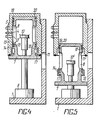
- the chamber 13 is closed at the top (in FIGS. 4, 5), and between At least one, in the variant described, two composite metal rings 14 are attached to it and the receiving base 7 on the part of its loading opening behind the elastic sealing ring 11 in the direction away from the edge of the chamber 13 toward the center, for which in the hollow cylinder (in the receiving base 7 ) annular grooves 15 are executed.
- the device according to the invention has a locking ring 16 with a flange 17, which is located in an inner recess 18 of the chamber 13 and can slide on the surface of the hollow cylinder.
- two composite metal rings 19 are designed in ring-shaped, at the upper (corresponding to FIGS. 4, 5) end of the hollow cylinder Grooves 20 attached.
- the device for thermal deburring of workpieces works as follows.
- the receiving base 7 (FIGS. 1, 2, 3) is in the lower position, as shown in FIG. 2.
- a workpiece 10 (or several workpieces) to be treated is placed on the table 9 through the window 8.
- the receiving base with the workpiece 10 is then lifted along the inner wall of the working chamber 2 with the aid of the pneumatic cylinder 6 and assumes the operating position, as shown in FIG. 1.
- the elastic sealing rings 11 and 12 ensure a hermetic seal of the interior of the working chamber 2, which is formed by the side walls of the working chamber 2 and the hollow cylinder and the covers on the end faces of the hollow cylinder (the receiving base 7).
- a fuel mixture is passed into its interior through the window 8 and the inlet valve 3, which is then ignited with the aid of the spark plug 4.
- the burrs on the workpiece 10 to be treated are burned and / or melted due to their developed surface and a relatively small mass.
- the pressure of the air in the pneumatic cylinder 6 is selected so that the hermetic seal of the chamber 13 is ensured at the initial characteristics during the time during which it is filled with a fuel mixture .
- the hermetic seal of the chamber 13 and the receiving base 7 is ensured by the composite metal rings 14, 19, so that the gases with high pressure and high temperature cannot act directly on the elastic sealing ring 11.
- the device according to the invention is designed according to a self-contained force scheme, i.e. it does not require any additional mechanisms for fixing the receiving base 7 to the chamber 13 (2) both in the period during which it is filled with a fuel mixture and in the burning period of the mixture, i.e. when the maximum pressure is in the chamber 13 (2).
- the pressure of the fuel mixture both at the initial parameters during the filling of the chamber and at the maximum parameters during the combustion process is taken up by the end walls of the hollow cylinder and its side surface and also by the side surface of the working chamber 13 (2) (through the windows 8) , ie the forces arising in the interior of the hollow cylinder and the working chamber 13 (2) are extinguished in their walls and are not transmitted to the pneumatic cylinder 6 and the frame 1.
- the invention can be used in mechanical engineering companies for cleaning workpieces made of metal and plastic.
Landscapes
- Physics & Mathematics (AREA)
- Thermal Sciences (AREA)
- Optics & Photonics (AREA)
- Engineering & Computer Science (AREA)
- Mechanical Engineering (AREA)
- Processing And Handling Of Plastics And Other Materials For Molding In General (AREA)
- Furnace Details (AREA)
- Nitrogen And Oxygen Or Sulfur-Condensed Heterocyclic Ring Systems (AREA)
- Pressure Welding/Diffusion-Bonding (AREA)
Abstract
Applications Claiming Priority (1)
| Application Number | Priority Date | Filing Date | Title |
|---|---|---|---|
| PCT/SU1986/000038 WO1987006511A1 (fr) | 1986-04-30 | 1986-04-30 | Dispositif pour l'ebarbage thermique |
Publications (2)
| Publication Number | Publication Date |
|---|---|
| EP0310665A4 EP0310665A4 (fr) | 1989-04-04 |
| EP0310665A1 true EP0310665A1 (fr) | 1989-04-12 |
Family
ID=21616990
Family Applications (1)
| Application Number | Title | Priority Date | Filing Date |
|---|---|---|---|
| EP86904466A Withdrawn EP0310665A1 (fr) | 1986-04-30 | 1986-04-30 | Dispositif pour l'ebarbage thermique |
Country Status (4)
| Country | Link |
|---|---|
| US (1) | US4796868A (fr) |
| EP (1) | EP0310665A1 (fr) |
| JP (1) | JPS63503128A (fr) |
| WO (1) | WO1987006511A1 (fr) |
Cited By (1)
| Publication number | Priority date | Publication date | Assignee | Title |
|---|---|---|---|---|
| DE102013219677A1 (de) * | 2013-09-30 | 2015-04-02 | Robert Bosch Gmbh | Thermische Entgratanlage mit beweglicher Tragbaugruppe |
Families Citing this family (4)
| Publication number | Priority date | Publication date | Assignee | Title |
|---|---|---|---|---|
| DE10116726A1 (de) * | 2001-04-04 | 2002-10-10 | Bosch Gmbh Robert | Anlage zur thermischen Behandlung von Werkstücken mit einem explosiven Gasgemisch, insbesondere thermische Entgratanlage |
| US8202473B2 (en) * | 2008-05-06 | 2012-06-19 | Kennametal Inc. | Framed TEM machine and method of operating same |
| US8157497B2 (en) * | 2008-05-06 | 2012-04-17 | Kennametal Inc. | Method and loader apparatus for TEM machine work chamber device |
| US7922833B2 (en) | 2008-08-05 | 2011-04-12 | Kennametal Inc. | Gas regulator for thermal energy machining |
Family Cites Families (7)
| Publication number | Priority date | Publication date | Assignee | Title |
|---|---|---|---|---|
| FR1568813A (fr) * | 1967-11-23 | 1969-05-30 | ||
| US3475229A (en) * | 1968-04-22 | 1969-10-28 | Chemotronics International Inc | Process for treating articles of manufacture to eliminate superfluous projections |
| US3666252A (en) * | 1970-05-25 | 1972-05-30 | Chemotronics International Inc | Apparatus for rapid high energy removal of superfluous projections |
| US4025062A (en) * | 1976-03-08 | 1977-05-24 | Surftran Company | Thermal deburring unit |
| DE3204995A1 (de) * | 1982-02-12 | 1983-08-25 | Robert Bosch Gmbh, 7000 Stuttgart | Vorrichtung zur behandlung von werkstuecken in einer brennkammer |
| DE3204997A1 (de) * | 1982-02-12 | 1983-08-25 | Robert Bosch Gmbh, 7000 Stuttgart | Vorrichtung zur behandlung von werkstuecken in einer brennkammer |
| DE3512015A1 (de) * | 1985-04-02 | 1986-10-02 | Robert Bosch Gmbh, 7000 Stuttgart | Vorrichtung zur behandlung von werkstuecken mittels temperatur- und druckstoessen durch zuenden eines brennbaren gasgemisches, insbesondere thermische entgratanlage |
-
1986
- 1986-04-30 WO PCT/SU1986/000038 patent/WO1987006511A1/fr not_active Ceased
- 1986-04-30 JP JP61503681A patent/JPS63503128A/ja active Pending
- 1986-04-30 EP EP86904466A patent/EP0310665A1/fr not_active Withdrawn
- 1986-04-30 US US07/165,263 patent/US4796868A/en not_active Expired - Fee Related
Cited By (1)
| Publication number | Priority date | Publication date | Assignee | Title |
|---|---|---|---|---|
| DE102013219677A1 (de) * | 2013-09-30 | 2015-04-02 | Robert Bosch Gmbh | Thermische Entgratanlage mit beweglicher Tragbaugruppe |
Also Published As
| Publication number | Publication date |
|---|---|
| JPS63503128A (ja) | 1988-11-17 |
| US4796868A (en) | 1989-01-10 |
| WO1987006511A1 (fr) | 1987-11-05 |
| EP0310665A4 (fr) | 1989-04-04 |
Similar Documents
| Publication | Publication Date | Title |
|---|---|---|
| DE3833502C2 (fr) | ||
| CH679272A5 (fr) | ||
| DE4138888A1 (de) | Gasgenerator, insbesondere rohrgasgenerator fuer ein aufblasbares aufprallkissen | |
| DE69212705T2 (de) | Vorrichtung zur Abführung von Abgasen, die innenliegend von Akkumulatorbatterien gebildet werden | |
| DE3204995A1 (de) | Vorrichtung zur behandlung von werkstuecken in einer brennkammer | |
| DE2710007A1 (de) | Vorrichtung zum thermischen entgraten | |
| DE2849363A1 (de) | Ein chemisches aufschlussgefaess | |
| DE3041549C2 (de) | Stoßdämpfer mit in einem Zylinder vorgesehenen fließfähigen Elastomer | |
| EP0264451B1 (fr) | Installation a impulsions thermiques pour l'ebarbage | |
| CH657087A5 (de) | Hydraulisches spaltgeraet. | |
| EP0272323B1 (fr) | Dispositif d'ebarbage thermique | |
| DE19752326B4 (de) | Vorrichtung zum dichten Verschweißen eines Hochdruckbehälters | |
| EP0458040A2 (fr) | Installation pour lavage au gaz avec une brique perforée et une brique pour lavage au gaz | |
| CH625638A5 (fr) | ||
| DE2737726C2 (de) | Gasdichte Durchführung | |
| DE513406C (de) | Loetverbindung | |
| DE3521184C2 (fr) | ||
| EP1074463A2 (fr) | Hélice à pas variable pour bateaux de loisirs à moteur | |
| DE764899C (de) | Vakuumgluehtopf | |
| DE69926228T2 (de) | Dichtungsvorrichtung | |
| DE2746396C3 (de) | Verfahren und Vorrichtung zum Instandsetzen der Steigrohrauskleidung einer Koksofenkammer | |
| DE2620239C3 (de) | Verfahren zum Beschicken eines Ofens mit radioaktiven oder anders kontaminierten brennbaren Stoffen und Vorrichtung zur Durchführung des Verfahrens | |
| DE130459C (fr) | ||
| DE2311978C3 (de) | Ventil zur vorübergehenden Beaufschlagung einer Druckmeßeinrichtung | |
| DE2551265C3 (de) | Vorrichtung zum gasdichten Absperren des Innenrohres der Hohlelektrode eines elektrothermischen Schmelzofens |
Legal Events
| Date | Code | Title | Description |
|---|---|---|---|
| PUAI | Public reference made under article 153(3) epc to a published international application that has entered the european phase |
Free format text: ORIGINAL CODE: 0009012 |
|
| 17P | Request for examination filed |
Effective date: 19871209 |
|
| AK | Designated contracting states |
Kind code of ref document: A1 Designated state(s): DE FR GB IT SE |
|
| A4 | Supplementary search report drawn up and despatched |
Effective date: 19890404 |
|
| 17Q | First examination report despatched |
Effective date: 19911105 |
|
| STAA | Information on the status of an ep patent application or granted ep patent |
Free format text: STATUS: THE APPLICATION IS DEEMED TO BE WITHDRAWN |
|
| 18D | Application deemed to be withdrawn |
Effective date: 19920315 |
|
| RIN1 | Information on inventor provided before grant (corrected) |
Inventor name: BOZHKO, VALERY PAVLOVICH Inventor name: STRIZHENKO, VITALY EVGENIEVICH Inventor name: LEVITYANSKY, IVAN ANISIMOVICH Inventor name: LOSEV, ALEXEI VASILIEVICH Inventor name: PLESHKOV, VIKTOR IVANOVICH |