EP0310746B1 - Maschine und Verfahren zum Vorbereiten von Strumpfhosen - Google Patents
Maschine und Verfahren zum Vorbereiten von Strumpfhosen Download PDFInfo
- Publication number
- EP0310746B1 EP0310746B1 EP88106374A EP88106374A EP0310746B1 EP 0310746 B1 EP0310746 B1 EP 0310746B1 EP 88106374 A EP88106374 A EP 88106374A EP 88106374 A EP88106374 A EP 88106374A EP 0310746 B1 EP0310746 B1 EP 0310746B1
- Authority
- EP
- European Patent Office
- Prior art keywords
- leg
- blanks
- rail
- garment
- limp
- Prior art date
- Legal status (The legal status is an assumption and is not a legal conclusion. Google has not performed a legal analysis and makes no representation as to the accuracy of the status listed.)
- Expired - Lifetime
Links
- 238000000034 method Methods 0.000 title claims description 10
- 230000008569 process Effects 0.000 title description 2
- 238000012546 transfer Methods 0.000 claims abstract description 28
- 238000004519 manufacturing process Methods 0.000 claims abstract description 12
- 230000007246 mechanism Effects 0.000 claims description 9
- 230000033001 locomotion Effects 0.000 claims description 7
- 238000013459 approach Methods 0.000 claims description 3
- 238000004826 seaming Methods 0.000 claims description 3
- 238000006073 displacement reaction Methods 0.000 claims 1
- 238000011144 upstream manufacturing Methods 0.000 description 6
- 230000004048 modification Effects 0.000 description 4
- 238000012986 modification Methods 0.000 description 4
- 230000009286 beneficial effect Effects 0.000 description 2
- 238000010276 construction Methods 0.000 description 2
- 238000005304 joining Methods 0.000 description 2
- 230000001133 acceleration Effects 0.000 description 1
- 238000005520 cutting process Methods 0.000 description 1
- 238000004043 dyeing Methods 0.000 description 1
- 239000004744 fabric Substances 0.000 description 1
- 230000010006 flight Effects 0.000 description 1
- 238000009940 knitting Methods 0.000 description 1
- 238000012856 packing Methods 0.000 description 1
Images

Classifications
-
- D—TEXTILES; PAPER
- D05—SEWING; EMBROIDERING; TUFTING
- D05B—SEWING
- D05B23/00—Sewing apparatus or machines not otherwise provided for
- D05B23/007—Sewing units for assembling parts of knitted panties or closing the stocking toe part
Definitions
- the present invention relates to a process and equipment for producing pantihose garments.
- hosiery starts with the knitting of open-ended leg blanks. At a subsequent stage their toe ends are closed and various finishing operations such as dyeing, boarding and packing are performed.
- various finishing operations such as dyeing, boarding and packing are performed.
- pairs of legs are joined together, most frequently after toe closing.
- hose legs are mounted on leg supports for the various operations to be performed thereon.
- hose manufacture involves several mountings/dismountings of hose on different leg supports. At least the mounting steps are accomplished in greater or smaller extent by hand. Such manual operations are time consuming, especially if hose have to be everted during the mounting, and with every manual handling the risk of damaging fragile knits increases.
- Toe closers are now available which enable paired legs, presented in the form of made-up pantihose, to be toe closed at effectively the same time.
- Two such machines are the Pantimatic toe closer and the Speedomatic HS manufactured by Detexomat Machinery Limited. (PANTIMATIC, SPEEDOMATIC and DETEXOMAT are Registered Trade Marks). With such machines as these, it can be beneficial to line close first and then to toe close.
- the equipment we have devised assists in the transfer of the limp fabric workpieces to a receiving machine having a receiving member such as a support upon which the workpieces are to be mounted e.g. pneumatically or by means of suction.
- the equipment is intended primarily, but not exclusively, to deliver the legs of part-finished pantihose from the hose supports of a hosiery line closer directly to the suction tubes of the leg supports of a toe closer.
- the equipment is designed to keep portions of the legs of pantihose, separate from one another during their transport and positively advances the portions so that they can be properly received and handled by the receiving station or machine.
- EP-A-0 126 800 discloses apparatus and method for producing pantihose, wherein a line closer is linked by a transferer assembly to a toe closer so that the legs joined by the line closer are automatically transferred and loaded onto the suction tube supports of the toe closer, ready for the latter to perform its toe closing operation.
- a line closer is linked by a transferer assembly to a toe closer so that the legs joined by the line closer are automatically transferred and loaded onto the suction tube supports of the toe closer, ready for the latter to perform its toe closing operation.
- the toe ends of the joined legs are presented to, and sucked into, the suction tube supports, while the joined, body portion of the garment remains held by the holders of the line closer.
- the body portion of the garment is subsequently grasped by the transferer assembly, stripped from the line closer holders, and everted onto the suction tube supports.
- the present invention has for an object an improved mode of transfer from a line closer to a receiving machine having a suction everter, which mode of transfer can permit acceleration of the production operation and hence increased productivity.
- This objective is met in this invention by stripping the garment body portion from the line closer holders immediately before the garment legs are sucked into the suction tube supports e.g. of a toe closer.
- the toe ends enter the suction tube supports after the body portion has been stripped from the line closer holders.
- Such early release of the body portion from the holders can enable the line closer operation to be accelerated beneficially. Stripping as aforesaid before the toe ends enter the suction tube supports is gained, in an embodiment described in detail herein, by appropriately controlling the operation of frictional drive means by which the legs are advanced in a positive and controlled manner to their allotted supports.
- the method defined in the last two paragraphs can be performed in conjunction with operatively juxtaposed line and toe closers used for the production of pantihose, in conjunction with operatively-juxtaposed line closers and suction everters, line closers and gusset inserting machines, and line closers and boarding machines, for instance.
- the present invention provides pantihose manufacturing equipment comprising (a) a line closer for receiving a pair of hose leg blanks on hose holders therefor, said holders being movable along a predetermined path to advance the blanks first past a seamer which is operative to join said blanks to form a pantihose body portion, and then to a transfer station; (b) a suction everter (e.g. of a toe closer) adjacent said transfer station for receiving the pantihose garment for everting it (e.g.
- the everter in readiness for closing to ends of the legs thereof) the everter having a pair of suction tubes each to receive therein, by suction, a respective garment leg; and (c) a transfer mechanism at the transfer station which is operative (i) to strip the body portion of the garment from the line closer holders and (ii) to carry said body portion to the everter and to dispose the body portion therearound in an everted condition, the equipment being characterised in that the transfer mechanism is operative to take hold of the said body portion and to strip it from the line closer holders immediately before the legs are presented to the suction tubes.
- the present invention provides for the operative interconnection of two machines which perform sequential work operations on hose, for instance a pantihose line closer and a toe closer or a line closer and a gusset inserting machine.
- the apparatus according to the invention enables each hose leg of a joined pair thereof to be presented correctly to a respective one of a pair of adjacent suction tubes of a hose everting or mounting device, of a toe closer, for instance.
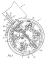
- the apparatus according to the invention shown in Fig. 1 is for transporting or guiding the legs of part-finished pantihose mounted on support means 11 of a line closer L to a pair of adjacent supports 12 of a toe closer T.
- a line closer is made by Takatori Machinery Works Limited of Yamatotakada City, Japan, under several model numbers LC-240, LC-280 and LC-320. Exemplary toe closers are noted hereinbefore.
- the apparatus being described ensures the hose legs reach the supports 12 of the toe closer T in such a manner that each hose leg is presented properly to the correct one of said supports 12.
- the line closer L has a plurality of hose supporters mounted at intervals about a horizontal carousel which rotates around a vertical central axis.
- Each supporter comprises a pair of leg supports 11, designed to hold two knitted legs to be joined. These supports 11 are parallel and adjacent at a loading station I of the line closer L.
- a hose supporter is shown in an open condition at a discharge station II. Following discharge, the leg supports are moved parallel and close to one another again ready for receiving new hose. In the course of their travel from station I to station II, the leg supports 11 are spread apart, properly to present the hose legs thereon to cutting and seaming means at station III. It is at this station that the legs are joined by a crutch or body seam.
- the joined legs are to be presented by the apparatus 10 to the mouths of two parallel and adjacent suction tubes 12′, and 12 ⁇ of a hose support 12 of the toe closer.
- it is the toe end portion which is presented first to the suction tubes 12′, 12 ⁇ , but it does not matter if the portion of the hose presented thereto is not actually the toe end.
- the body part of the pantihose is, however, to be drawn over or around the support 12.
- Means for stripping the body portion of a part-finished pantihose H from a supporter of the line closer L and for loading the body portion onto a toe closer support 12 are not illustrated in Fig. 1, to avoid over-complicating the drawing.
- An exemplary stripping and loading mechanism is shown in Fig. 4 and can comprise two hose grippers 13 affixed to a carriage 14 reciprocally-movable, along a rail 15 lead screw or the like, lengthwise of the support 12. In a forwardmost position of the carriage 14, the two grippers 13 are moved into engagement with the waistband of a pantihose garment H mounted on the line closer supporter. This movement may involve one gripper moving downwardly from above the supporter and one upwardly from below.
- One gripper 13 takes hold of the waistband portion in the region of P while the other takes hold of a diametrically-opposed portion.
- the carriage 14 is caused to travel (in the direction of arrow X) towards the toe closer turret from which the toe closer supports 12 project.
- the grippers 13 strip the pantihose from the leg supports 11 of the line closer L.
- the grippers draw the pantihose body onto the two adjacent suction tubes of toe closer support 12.
- the pantihose legs 20, 21 are located within the respective suction tubes 12′, 12 ⁇ of the support 12.
- the grippers 13 may move apart (in the direction of arrow Y) to "open" the body during an appropriate part of the carriage travel.
- the toe closer T is so disposed that its supports 12 extend in the direction of the line closer discharge station II. Moreover, as the toe closer turret indexes bringing supports 12 successively to this station, the suction tubes 12′, 12 ⁇ are placed in positions adjacent a delivery end of the apparatus 10.
- the supports 11 of line closer L are in a horizontal plane.
- the suction tubes 12′, 12 ⁇ may likewise be in a horizontal plane although, depending on the precise construction of the toe closer T, they may be in a vertical plane or in a plane inclined at some other angle between the horizontal and vertical.
- the apparatus 10 has its delivery end configured according to the disposition of the tubes, so as to deliver each hose leg reliably to the open end of its proper suction tube.
- the stripping and loading mechanism may be required to rotate the hose body through a certain angle in the course of its transfer operation.
- Hose rotation can be effected by rotating the grippers 13 as a unit relative to the carriage 14 or to the rail 15, depending on the construction of the stripping and loading mechanism.
- the standard line closer L has a circular, horizontal rail encircling its carousel 26.
- the machine operator mounts the welt ends of two separate legs on the leg supports 11 and drapes the lower leg portions over the rail. The legs remain draped over the rail as the carousel rotates, carrying them towards the discharge station II. In the absence of this invention, it is not possible for the draped legs to be presented properly to the suction tubes 12′, 12 ⁇ at the station II.
- the exemplary equipment illustrated includes means to separate the hose legs as they are moved with the carousel 26 towards the discharge station II.
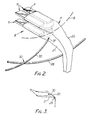
- the separating means comprises two stationary, arcuate guide rails 28, 30 both of which extend around the periphery of the line closer L to the discharge station II.
- the first rail 28 extends from the loading station (I). In use, the operator drapes both hose legs over this rail in the course of loading hose onto the line closer L.
- Rail 28 may be the circular rail already forming part of the commercial Takatori line closer or a modification thereof. Modification may be needed e.g. to dispose its discharge end 29 at a height and radial position suiting a related one of the suction tubes 12 ⁇ of the toe closer T.
- the second rail 30 has an upstream end 31 adjacent but downstream of the loading station I.
- Upstream end 31 is tapered and is located beside the path B swept by the outer ends of the leg supports 11 as the carousel 26 rotates. Further, said end 31 is positioned such that the two legs 20, 21 extending fom the supports 11 to the rail 28 are respectively caused to pass over and under rail 30. Lower leg 21 passes under rail 30 while upper leg 20 passes over rail 30. The end 31 is therefore interposed between the legs 20, 21 moving with the carousel 26.
- rail 30 curves outwardly and upwardly.
- the rails 28, 30 will be seen to cross at 32.
- rail 30 is above rail 28.
- the rail 30 continues to curve outwardly until it is disposed both above and radially beyond rail 28.
- the shape of rail 30 can be considered to be a gentle spiral when view in plan, but in reality is a gentle helix.
- the rails 28, 30 keep the moving hose legs separate and guide their respective legs thus to the associated suction tube 12′, 12 ⁇ .
- the suction tubes 12′, 12 ⁇ are in different horizontal and vertical planes.
- the ends 29, 33 of the rails 28, 30 are similarly spaced apart and are located beside the mouths of their associated tubes (12 ⁇ and 12′ respectively). The arrangement ensures upper hose leg 20 on rail 30 only enters tube 12′ while lower leg 21 on rail 28 only enters tube 12 ⁇ .
- Each conveyor 40, 41 comprises an endless belt 42 trained around drive 43 and idler 44 pulleys, and driven by an electric motor preferably of variable speed type.
- Conveyor 40 advances the hanging portion of upper hose leg 20 along the rail 30 to rail end 33 and thence to the nearer suction tube 12′.
- Conveyor 41 advances the hanging portion of lower hose leg 21 somewhat beyond the rail end 33 and the nearer suction tube 12′, to a position in front of the farther suction tube 12 ⁇ . Conveyor 41 thus advances leg 21 to the end 29 of associated rail 28, and thereupon releases the leg 21 to tube 12 ⁇ .
- the conveyors 40, 41 might be continuously or intermittently driven.
- Each conveyor belt 42 could have its conveying flight running on the associated rail.
- each of the conveying flights runs against a vertical support panel or skirt 44, 46. Said skirts depend from the rails 28, 30 and extend therealong upstream from their ends 29, 33 to positions in the vicinity of the pulleys 44.
- skirts 44, 46 and conveyors preclude any possibility of the draped hose legs 20, 21 tangling with one another, said skirts assisting the rails therefore in keeping the hose legs separate.
- the legs 20, 21 will ordinarily be the same length, of course. Rail 28 is closer to, and rail 30 is farther from, the path B so the length of lower leg 21 which hangs down from rail 28 will be greater than the length of upper leg 20 hanging from rail 30. If conveyor 41 had its conveying flight close and parallel to rail 28 (akin to conveyor 40), it could take hold of a middle part of leg 21 and present that to the suction tube 12 ⁇ . Presentation of the middle part to the suction tube 12 ⁇ , rather than a foot or toe end portion of the hose leg 21, could perturb hose transfer to the toe closer T. Accordingly, we position pulley 44 of conveyor 41 lower, relative to rail 28, than pulley 42. The conveyor 41 thus has its conveying flight inclined upwardly to the rail end 29.
- the conveyor 41 can be made to take hold of a portion of the hose leg 21 closer to the foot or toe end when the leg first reaches the conveyor.
- the moving conveyor belt 42 then elevates the foot or toe end portion to the region of the suction tube 12 ⁇ .
- the skirt or panel 44 depending from the upper rail 30 has a sufficient depth, or vertical extent, to ensure the upper leg 20 cannot be seized by the conveyor 41.
- either or both guide rail 28, 30 can have its end or a terminal extension projecting laterally beyond the associated suction tube, to ensure the hose legs cannot inadvertently escape from the influence of suction in the suction tube.
- the invention is not limited to the apparatus being associated, as shown, with a line closer and a toe closer.
- the apparatus 10 could transport hose on a line closer towards a boarding machine located at station II.
- the apparatus could transport hose, inter alia in the form of socks, towards a boarding machine from a looper line closer.
- the hose - or other garments - are moving in a circular path when they encounter the present apparatus.
- the said articles could be moving along a straight path when the limp, hanging portions thereof meet the means which separates them.
- the invention is not limited, so far as concerns hosiery manufacture, to garment transfer, specifically from a line closer to a toe closer.
- the transfer or loading apparatus 10 disclosed above could be incorporated in any hosiery conveyor provided in a hosiery manufactory for delivering pantihose to a production machine the needs of which demand that the legs of arriving garments be separated.
- a toe closer is exemplary of such a machine.
- Another example is a boarding machine which has a pair of leg forms over which the legs are to be drawn for boarding.
- One such machine is disclosed in U.S. Patent 4,434,918 to Hodges.
- Yet another example is a gusset-inserting machine of the general type disclosed in GB 2,001,238 to Flude.
- Such a machine has a gussetting head onto which a body portion of the pantihose is mounted.
- the gussetting head is conveniently associated with suction tube leg receivers operable while the body portion is being mounted on the gussetting head.
- Mounting of the body portion is a task fulfilled by a stripping and loading mechanism such as has been described in connection with Fig. 4.
- the apparatus 10 is primarily designed, however, as a means operatively to link a line closer with a toe closer or with a gusset inserting machine.
- frictional drive means comprising the conveyers 40, 41 are located adjacent the station whereat the pantihose garment is transferred to the toe closer T, so as to engage or grip the legs of the garment during their final approach to said transfer station.
- Each conveyor could, however, extend appreciably further upstream than in the accompanying illustrations. This could facilitate proper control of the garment during its movement towards the transfer station, to ensure the individual legs and body portion arrive thereat in properly timed sequence. It may be beneficial for the conveyors to extend as far upstream from the transfer station as the vicinity of the operator's loading station I. The operator will then place the hose legs on their respective supports 11 and offer their limp portions to the respective conveyors therefor.
- Said conveyors can be trained to run each in contact with a respective one of the opposite sides of a single guide rail.
- the divergent rail 30 could be omitted, and rail 28 alone employed; the depth of this rail would be increased e.g. by a vertical skirt to provide an adequate surface for contact by the conveying means.
Landscapes
- Engineering & Computer Science (AREA)
- Textile Engineering (AREA)
- Treatment Of Fiber Materials (AREA)
- Intermediate Stations On Conveyors (AREA)
- Sewing Machines And Sewing (AREA)
- Specific Conveyance Elements (AREA)
- Chain Conveyers (AREA)
- Macromonomer-Based Addition Polymer (AREA)
- Saccharide Compounds (AREA)
Claims (13)
- Verfahren, zum Herstellen eines Strumpfhosen-Kleidungsstücks aus zwei offenendigen Beinrohlingen, mit den Schritten, daßa) die Rohlinge aufgegeben werden auf Strumpfhalter (11) einer Linienschließmaschine (L) bereit für eine Nahtverbindung der Beinrohlinge auf dieser Maschine zur Bildung eines Rumpfteils des Kleidungsstücks,b) die Rohlinge auf den Haltern (11) zu einer Abgabestation (II) der Linienschließvorrichtung vorbewegt werden, in der sich daneben angeordnet ein Saugwendeorgan mit einem Paar von Saugrohr-Strumpfbeinträgern (12', 12'') befindet, an die das Kleidungsstück im Laufe der Vorbewegung der Rohlinge zu übertragen ist, indem sie an einer Nahtbildevorrichtung zum Vereinigen der Beinrohlinge und zur Bildung des Rumpfteils des Kleidungsstücks (H) vorbeibewegt werden, undc) das Kleidungsstück (H) bei Ankunft an der Abgabestation von den Haltern (11) der Linienschließvorrichtung an die Saugrohrträger (12', 12'') übertragen wird, wobei der Übertragungsschritt die Maßnahmen umfaßt, daß jedes Bein des Kleidungsstücks dem jeweiligen der Träger (12', 12'') dargeboten wird, damit die Beine in ihre zugeordneten Träger eingesaugt werden, der Kleidungsstückrumpf von den Haltern (11) der Linienschließvorrichtung abgestreift wird und der Rumpfteil um die beiden Träger (12', 12'') in einen gewendeten Zustand gelegt wird, mit der Kennzeichnung des Schrittes c) dadurch, daß der Kleidungsstückrumpf von den Haltern (11) der Linienschließvorrichtung abgestreift wird, unmittelbar bevor die Beine des Kleidungsstücks (20, 21) in die Träger (12', 12'') eingesaugt werden.
- Verfahren nach Anspruch 1, bei den das Saugwendeorgan mit den Paar von Beinträgern (12', 12'') einen Teil einer Fußspitzenschließvorrichtung (T) bildet und nach der Übertragung des Kleidungsstücks (H) an die Beinträger (12', 12'') die Fußspitzenenden der Rohlinge durch Betätigung der Fußspitzenschließvorrichtung (T) geschlossen werden.
- Verfahren nach Anspruch 1 oder Anspruch 2, bei den bei dem Schritt b) Beinteile der Rohlinge getrennt voneinander zu der Abgabestation (II) vorbewegt und die Beinteile zumindest bei ihrer Schlußannäherung an diese Station von Reibantriebsmitteln erfaßt werden, indem zum Beispiel die Beinteile zwischen den Antriebsmitteln und zugehörigen Führungsmitteln erfaßt werden und dadurch jeder Beinteil für sich und zwangsläufig in gesteuerter Weise zu seinen zugehörigen Saugrohrträger (12', 12'') vorbewegt wird.
- Verfahren nach Anspruch 3, bei dem Endlosfördermittel als Reibantriebsmittel verwendet werden.
- Verfahren nach Anspruch 1, 2, 3 oder 4, bei den die Beinteile infolge ihrer Bewegung in Richtung der Abgabestation (II) getrennt werden, indem die Beinteile relativ zueinander, um sie zu trennen, dadurch verlagert werden, daß sie zwangläufig auf verschiedenen, divergierenden Strecken vorbewegt werden, die jeweils zu einem bestimmten der Saugrohrträger (12', 12'') führen.
- Verfahren nach einem beliebigen der vorhergehenden Ansprüche, bei dem die Beinrohlinge entlang einer im allgemeinen kreisförmigen Strecke zu der Station (II) hinbewegt werden, wobei ein lappiger Beinteil (21) entlang einer kreisförmigen Strecke bewegt wird, die von einem kreisförmig ausgebildeten Führungsglied (28) gebildet ist, über das der Beinteil drapiert ist, und der andere lappige Beinteil (20) entlang einer angrenzenden Strecke bewegt wird, die von einem zweiten Führungsglied (30) mit einem Bereich von im wesentlichen Schraubenlinienform gebildet ist.
- Einrichtung zur Strumpfhosenherstellung, bestehend aus a) einer Linienschließvorrichtung (L) zur Aufnahme eines Paares von Strumpfbeinrohlingen (20, 21) auf Strumpfhaltern (11) für diese, wobei die Halter entlang einer vorbestimmten Strecke bewegbar sind, um die Rohlinge an einer Nahtbildevorrichtung vorbei, die im Betrieb die Rohlinge zur Bildung eines Strumpfhosenrumpfteils (P) vereinigt, und dann zu einer Übergabestation vorzubewegen, b) einem Saugwendeorgan (z.B. einer Fußspitzenschließvorrichtung (T)) angrenzend an die Übertragungsstation zur Aufnahme des Strumpfhosen-Kleidungsstücks (H), um es zu wenden (z.B. in Bereitstellung zum Schließen der Fußspitzenden seiner Beine (20,21)), wobei das Wendeorgan ein Paar von Saugrohren (12', 12'') besitzt, um jeweils darin durch Saugwirkung ein jeweiliges Bein (20, 21) des Kleidungsstücks aufzunehmen, und c) einem Übertragungsmechanismus (13,14,15) an der Übertragungsstation, der im Betrieb i) den Rumpfteil (P) des Kleidungsstücks (H) von den Haltern (11) der Linienschließvorrichtung abstreift und ii) den Rumpfteil zum Wendeorgan trägt sowie den Rumpfteil um diesen in einem gewendeten Zustand anordnet, wobei die Einrichtung dadurch gekennzeichnet ist, daß der Übertragungsmechanismus im Betrieb den Rumpfteil (P) erfaßt und ihn von den Haltern (11) der Linienschließvorrichtung abstreift, unmittelbar bevor die Beine (20,21) den Saugrohren (12',12'') dargeboten werden.
- Einrichtung nach Anspruch 7, bei der die Linienschließvorrichtung (L) dazu eingerichtet ist, die voneinander getrennten Beinrohlinge zu der Übergabestation vorzubewegen, und mit einem Reibantrieb für einen Eingriff mit den Beinrohlingen für ein individuelles und zwangläufiges Vorbewegen von lappigen Teilen der Beinrohlinge in einer gesteuerten Weise zu ihren zugeordneten Saugrohren (12',12'') versehen ist.
- Einrichtung nach Anspruch 8, bei der ein Endlosfördermittel den Reibantrieb umfaßt.
- Einrichtung nach Anspruch 8 oder Anspruch 9, bei der der Reibantrieb im Betrieb die lappigen Teile zumindest in Verlauf ihrer Schlußannäherung an die Übergabestation (II) erfaßt und vorbewegt.
- Einrichtung nach Anspruch 7, 8, 9 oder 10, bei der die Linienschließvorrichtung (L) langgestreckte, zu den Saugrohren (12',12'') verlaufende Führungsmittel (28,30) aufweist, über die lappige Teile der Beinrohlinge drapiert und im Betrieb vorbewegt werden, wobei die Führungsmittel eine Konfiguration besitzen, die infolge der Bewegung der Kleidungsstücke entlang dieser im Betrieb eine relative Trennverlagerung der lappigen Teile herbeiführt.
- Einrichtung nach Anspruch 11, bei der die Führungsmittel für die lappigen Teile divergierende Schienen (28,30) jeweils zum Abstützen eines lappigen Teils bei seiner Bewegung umfassen und die Schienen sich zu dem jeweiligen Saugrohr (12',12'') hin estrecken.
- Einrichtung nach Anspruch 12, bei der eine Schiene (30) mit einem Ende (31) angrenzend an einen Zwischenbereich der anderen Schiene (28) angeordnet ist, derart, daß im Betrieb, wenn zwei über diese andere Schiene (28) drapierte lappige Teile (20,21) entlang dieser zu diesem Ende der einen Schiene (30) hin vorbewegt werden, die letztere Schiene zwischen die lappigen Teile zwischengeschoben wird und danach diese jeweils über eine Schiene drapiert werden, wobei eine Schiene zum Beispiel von kreisförmiger Gestalt ist und die andere Schiene einen schraubenlinienförmig gestalteten Bereiche besitzt, der von der einen Schiene nach oben und außen divergiert.
Priority Applications (1)
| Application Number | Priority Date | Filing Date | Title |
|---|---|---|---|
| AT88106374T ATE85093T1 (de) | 1984-04-17 | 1985-04-17 | Maschine und verfahren zum vorbereiten von strumpfhosen. |
Applications Claiming Priority (2)
| Application Number | Priority Date | Filing Date | Title |
|---|---|---|---|
| GB8409884 | 1984-04-17 | ||
| GB848409884A GB8409884D0 (en) | 1984-04-17 | 1984-04-17 | Transporting fabric pieces |
Related Parent Applications (1)
| Application Number | Title | Priority Date | Filing Date |
|---|---|---|---|
| EP85302673.0 Division | 1985-04-17 |
Publications (3)
| Publication Number | Publication Date |
|---|---|
| EP0310746A2 EP0310746A2 (de) | 1989-04-12 |
| EP0310746A3 EP0310746A3 (en) | 1989-10-04 |
| EP0310746B1 true EP0310746B1 (de) | 1993-01-27 |
Family
ID=10559728
Family Applications (2)
| Application Number | Title | Priority Date | Filing Date |
|---|---|---|---|
| EP85302673A Expired EP0174059B1 (de) | 1984-04-17 | 1985-04-17 | Vorrichtung um Werkstücke einer Überwendlingsnähmaschine zu einer anderen Maschine zu bringen |
| EP88106374A Expired - Lifetime EP0310746B1 (de) | 1984-04-17 | 1985-04-17 | Maschine und Verfahren zum Vorbereiten von Strumpfhosen |
Family Applications Before (1)
| Application Number | Title | Priority Date | Filing Date |
|---|---|---|---|
| EP85302673A Expired EP0174059B1 (de) | 1984-04-17 | 1985-04-17 | Vorrichtung um Werkstücke einer Überwendlingsnähmaschine zu einer anderen Maschine zu bringen |
Country Status (5)
| Country | Link |
|---|---|
| US (1) | US4628844A (de) |
| EP (2) | EP0174059B1 (de) |
| AT (2) | ATE85093T1 (de) |
| DE (2) | DE3587047D1 (de) |
| GB (1) | GB8409884D0 (de) |
Families Citing this family (4)
| Publication number | Priority date | Publication date | Assignee | Title |
|---|---|---|---|---|
| EP0230724B1 (de) * | 1985-11-26 | 1992-04-15 | Detexomat Machinery Limited | Tranporteinrichtung und -verfahren für Bekleidung, zum Beispiel Strumpfwaren |
| IT1213803B (it) * | 1987-07-14 | 1990-01-05 | Solis Srl | Metodo e macchina per il trasferimento automatico dei collant e simili manufatti da unamacchina di cucitura delle punte ad una macchina da stiro |
| GB8910318D0 (en) * | 1989-05-05 | 1989-06-21 | Flude & Hinckley | Apparatus for loading a line closing machine |
| GB9127050D0 (en) * | 1991-12-20 | 1992-02-19 | Orion Yhtymae Oy | Substituted imidazole derivatives and their preparation and use |
Family Cites Families (11)
| Publication number | Priority date | Publication date | Assignee | Title |
|---|---|---|---|---|
| US2905366A (en) * | 1956-12-12 | 1959-09-22 | Floyd R Shoaf | Apparatus for feeding hosiery onto a receiving member |
| FR2211951A5 (en) * | 1972-12-21 | 1974-07-19 | Heliot Maurice Ets | Handling device with rotatable platform for panty hose - automatically removes them from formers and deposits them on a rail |
| IT7809326A0 (it) * | 1978-01-27 | 1978-01-27 | Chietti Giovanni | Apparecchiatura semiautomatica per il caricamento di manufatti tubolari per calze o simili su macchine cucitrici e per altri impieghi |
| JPS5731891A (en) * | 1980-07-31 | 1982-02-20 | Sukeo Mori | Inserting fitting device for stocking cloth in end automatic sewing machine for seamless stocking |
| EP0057055B1 (de) * | 1981-01-23 | 1985-04-17 | Detexomat Machinery Limited | Einrichtung und Verfahren zur Behandlung von Strümpfen |
| US4364320A (en) * | 1981-02-23 | 1982-12-21 | Consolidated Foods Corporation | Garment toe closing system |
| US4487546A (en) * | 1981-08-05 | 1984-12-11 | Savio & C. S.P.A. | Device for transferring tubular fabrics from support hangers to a rigid body and inverting the fabric |
| US4444140A (en) * | 1981-12-14 | 1984-04-24 | Monarch Knitting Machinery Corporation | Method of making panty hose and apparatus to make same |
| GB8303159D0 (en) * | 1983-02-04 | 1983-03-09 | Detexomat Machinery Ltd | Transferring hosiery between manufacturing machines |
| JPS59218188A (ja) * | 1983-05-26 | 1984-12-08 | 株式会社タカトリ機械製作所 | ホ−ス端部の自動位置決め方法および装置 |
| EP0126800B1 (de) * | 1983-05-31 | 1988-01-20 | Takatori Machinery Works Ltd. | Maschine und Verfahren um Strumpfhose automatisch und anhaltend zu schliessen |
-
1984
- 1984-04-17 GB GB848409884A patent/GB8409884D0/en active Pending
-
1985
- 1985-04-17 EP EP85302673A patent/EP0174059B1/de not_active Expired
- 1985-04-17 DE DE8888106374T patent/DE3587047D1/de not_active Expired - Lifetime
- 1985-04-17 DE DE8585302673T patent/DE3581457D1/de not_active Expired - Lifetime
- 1985-04-17 AT AT88106374T patent/ATE85093T1/de active
- 1985-04-17 US US06/724,246 patent/US4628844A/en not_active Expired - Fee Related
- 1985-04-17 AT AT85302673T patent/ATE60377T1/de not_active IP Right Cessation
- 1985-04-17 EP EP88106374A patent/EP0310746B1/de not_active Expired - Lifetime
Also Published As
| Publication number | Publication date |
|---|---|
| EP0310746A2 (de) | 1989-04-12 |
| DE3581457D1 (de) | 1991-02-28 |
| EP0174059B1 (de) | 1991-01-23 |
| EP0310746A3 (en) | 1989-10-04 |
| EP0174059A1 (de) | 1986-03-12 |
| DE3587047D1 (de) | 1993-03-11 |
| ATE60377T1 (de) | 1991-02-15 |
| ATE85093T1 (de) | 1993-02-15 |
| GB8409884D0 (en) | 1984-05-31 |
| US4628844A (en) | 1986-12-16 |
Similar Documents
| Publication | Publication Date | Title |
|---|---|---|
| US3589320A (en) | Pocket blank sewing machine | |
| US4550868A (en) | Method and apparatus for transferring hosiery between hosiery manufacturing machines | |
| EP0508014B1 (de) | Materialhandhabungssystem | |
| US6158367A (en) | Apparatus and method for automatically orienting hosiery articles for closing toe ends thereof | |
| US4862815A (en) | Pantihose manufacture | |
| US4539924A (en) | Loading system for a toe closing assembly | |
| US4133280A (en) | Automatic method and apparatus for closing a toe end of a hose utilizing a straight line stitch | |
| US4649838A (en) | Process and machine for sewing the toes of pantyhoses with feed from a machine for forming pantyhoses and with ejection suitable for a subsequent automated transfer of the product | |
| US4903621A (en) | Hosiery toe closing method and apparatus | |
| EP0310746B1 (de) | Maschine und Verfahren zum Vorbereiten von Strumpfhosen | |
| US8646594B2 (en) | Apparatus for automatic transfer of textile articles from a linking machine to a boarding machine | |
| US4957051A (en) | Automatic fitting apparatus for hose part of half made pantyhose | |
| USRE32481E (en) | Boarding apparatus | |
| WO2004067419A1 (en) | Apparatus and method for automatically orienting hosiery articles for closing toe ends thereof | |
| US5511501A (en) | Method and apparatus for handling flexible objects | |
| US4602710A (en) | Loading system for a toe closing assembly | |
| JPH0117400B2 (de) | ||
| US4383490A (en) | Hosiery toe closing machine | |
| US4440329A (en) | Apparatus for unloading hosiery machinery | |
| US7025011B2 (en) | Apparatus for automatically orienting hosiery articles for closing toe ends thereof | |
| CN101243223A (zh) | 用于处理管形针织品例如长袜和短袜等的装置和方法 | |
| EP0075477A1 (de) | Nähschliessvorrichtung für Strickstrumpf | |
| EP0152170A2 (de) | Nähverfahren und Nähvorrichtung | |
| US4748924A (en) | Hosiery transport | |
| WO2019239441A1 (en) | Apparatus for controlling men's socks |
Legal Events
| Date | Code | Title | Description |
|---|---|---|---|
| PUAI | Public reference made under article 153(3) epc to a published international application that has entered the european phase |
Free format text: ORIGINAL CODE: 0009012 |
|
| AC | Divisional application: reference to earlier application |
Ref document number: 174059 Country of ref document: EP |
|
| AK | Designated contracting states |
Kind code of ref document: A2 Designated state(s): AT BE CH DE FR GB IT LI LU NL SE |
|
| PUAL | Search report despatched |
Free format text: ORIGINAL CODE: 0009013 |
|
| AK | Designated contracting states |
Kind code of ref document: A3 Designated state(s): AT BE CH DE FR GB IT LI LU NL SE |
|
| 17P | Request for examination filed |
Effective date: 19890908 |
|
| 17Q | First examination report despatched |
Effective date: 19910705 |
|
| GRAA | (expected) grant |
Free format text: ORIGINAL CODE: 0009210 |
|
| ITF | It: translation for a ep patent filed | ||
| AC | Divisional application: reference to earlier application |
Ref document number: 174059 Country of ref document: EP |
|
| AK | Designated contracting states |
Kind code of ref document: B1 Designated state(s): AT BE CH DE FR GB IT LI LU NL SE |
|
| PG25 | Lapsed in a contracting state [announced via postgrant information from national office to epo] |
Ref country code: SE Effective date: 19930127 Ref country code: NL Effective date: 19930127 Ref country code: LI Effective date: 19930127 Ref country code: DE Effective date: 19930127 Ref country code: CH Effective date: 19930127 Ref country code: BE Effective date: 19930127 Ref country code: AT Effective date: 19930127 |
|
| REF | Corresponds to: |
Ref document number: 85093 Country of ref document: AT Date of ref document: 19930215 Kind code of ref document: T |
|
| ET | Fr: translation filed | ||
| REF | Corresponds to: |
Ref document number: 3587047 Country of ref document: DE Date of ref document: 19930311 |
|
| PG25 | Lapsed in a contracting state [announced via postgrant information from national office to epo] |
Ref country code: GB Effective date: 19930427 |
|
| PG25 | Lapsed in a contracting state [announced via postgrant information from national office to epo] |
Ref country code: LU Free format text: LAPSE BECAUSE OF NON-PAYMENT OF DUE FEES Effective date: 19930430 |
|
| REG | Reference to a national code |
Ref country code: CH Ref legal event code: PL |
|
| NLV1 | Nl: lapsed or annulled due to failure to fulfill the requirements of art. 29p and 29m of the patents act | ||
| PLBE | No opposition filed within time limit |
Free format text: ORIGINAL CODE: 0009261 |
|
| STAA | Information on the status of an ep patent application or granted ep patent |
Free format text: STATUS: NO OPPOSITION FILED WITHIN TIME LIMIT |
|
| GBPC | Gb: european patent ceased through non-payment of renewal fee |
Effective date: 19930427 |
|
| PG25 | Lapsed in a contracting state [announced via postgrant information from national office to epo] |
Ref country code: FR Effective date: 19931229 |
|
| 26N | No opposition filed | ||
| REG | Reference to a national code |
Ref country code: FR Ref legal event code: ST |