EP0310768A1 - Digitaler Impulsgeber - Google Patents
Digitaler Impulsgeber Download PDFInfo
- Publication number
- EP0310768A1 EP0310768A1 EP88111953A EP88111953A EP0310768A1 EP 0310768 A1 EP0310768 A1 EP 0310768A1 EP 88111953 A EP88111953 A EP 88111953A EP 88111953 A EP88111953 A EP 88111953A EP 0310768 A1 EP0310768 A1 EP 0310768A1
- Authority
- EP
- European Patent Office
- Prior art keywords
- pulse generator
- arrangement according
- disc
- digital
- changes
- Prior art date
- Legal status (The legal status is an assumption and is not a legal conclusion. Google has not performed a legal analysis and makes no representation as to the accuracy of the status listed.)
- Granted
Links
- 230000001419 dependent effect Effects 0.000 claims description 2
- 230000000694 effects Effects 0.000 description 3
- 230000005355 Hall effect Effects 0.000 description 1
- 230000004888 barrier function Effects 0.000 description 1
- 238000006243 chemical reaction Methods 0.000 description 1
- 230000002996 emotional effect Effects 0.000 description 1
- 238000011156 evaluation Methods 0.000 description 1
- 230000005693 optoelectronics Effects 0.000 description 1
Images
Classifications
-
- H—ELECTRICITY
- H03—ELECTRONIC CIRCUITRY
- H03M—CODING; DECODING; CODE CONVERSION IN GENERAL
- H03M1/00—Analogue/digital conversion; Digital/analogue conversion
- H03M1/12—Analogue/digital converters
- H03M1/22—Analogue/digital converters pattern-reading type
- H03M1/24—Analogue/digital converters pattern-reading type using relatively movable reader and disc or strip
-
- G—PHYSICS
- G01—MEASURING; TESTING
- G01P—MEASURING LINEAR OR ANGULAR SPEED, ACCELERATION, DECELERATION, OR SHOCK; INDICATING PRESENCE, ABSENCE, OR DIRECTION, OF MOVEMENT
- G01P13/00—Indicating or recording presence, absence, or direction, of movement
- G01P13/02—Indicating direction only, e.g. by weather vane
- G01P13/04—Indicating positive or negative direction of a linear movement or clockwise or anti-clockwise direction of a rotational movement
-
- G—PHYSICS
- G05—CONTROLLING; REGULATING
- G05G—CONTROL DEVICES OR SYSTEMS INSOFAR AS CHARACTERISED BY MECHANICAL FEATURES ONLY
- G05G5/00—Means for preventing, limiting or returning the movements of parts of a control mechanism, e.g. locking controlling member
- G05G5/02—Means preventing undesired movements of a controlling member which can be moved in two or more separate steps or ways, e.g. restricting to a stepwise movement or to a particular sequence of movements
Definitions
- the invention relates to a digital pulse generator with a rotatable disc and with these interacting sensors for delivering digital, direction-dependent pulses.
- Such pulse generators are known in digital technology as digital encoders. They consist of a rotatable disc that can be mechanically scanned by sliding contacts, optically by opto-electronic sensors or magnetically based on the Hall effect, or inductively scanned. The disc is moved past the triggering element such as grinder, photodiode, Hall element or coil. These are two sensors that are offset by a certain angle. The direction of rotation of the pulse generator can be deduced from the phase-shifted pulse series supplied by them, so that, for example, a counter connected to it counts up or down, from which the counting result can be evaluated digitally or after conversion.
- the mechanical torque of these pulse generators is determined by design and constant.
- Pulse generators of the type described above are widespread in digital electronics and are also gaining in importance in consumer electronics.
- the pulse generator is used several times by controlling different functions one after the other depending on the operating command of the device user. It is possible, for example, to change the transmitter setting, the volume setting, the bass and treble setting and the tonal balance of the device using this single pulse generator. This is done in such a way that these different functions are assigned to the pulse generator by preselection buttons.
- the invention has for its object to design a pulse generator such that its operation is facilitated. This object is achieved by the invention specified in claim 1. Further advantageous embodiments of the invention result from the subclaims.
- the invention has the advantage that the pulse generator for adjusting the volume acts differently due to a latched behavior than e.g. when changing the station selection, in which the pulse generator has a flywheel-like character.
- a constant higher torque may be desirable.
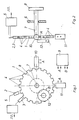
- FIGS. 1 and 2 A conventional structure of a pulse generator is shown schematically in FIGS. 1 and 2. It consists of a disk 1, which also has uniform projections 4 on its circumference at uniform angular intervals. These act on sensors 2 and 3, which consist of coils, which interact with the projections 4 of the disk 1, which are designed as magnets. However, the sensors 2 and 3 can also be designed in the form of fork light barriers which comprise the projections 4 of the pane 1. From the signals of the sensors 2 and 3, both the direction of rotation of the disk 1 and the number of pulses are detected in an evaluation circuit 5 for the purpose of step-by-step adjustment of a value for the adjustment of function variables.
- the disc 1 is moved via an axle 7 which is mounted in a bearing 6 and which the operator drives via a handle 8.
- a current is sent via a control unit 9 through magnets 10 and 11, which are arranged at a certain angular distance on the circumference of the disk 1 relative to the projections 4. This results in an emotional rotation of the disk 1 in small angular steps.
- the strength of the raster effect can be set by the magnitude of the current through the magnets 10 and 11.
- the control unit 9 excites an eddy current brake 12, the effectiveness of which is generated by a current of the appropriate size generated by the control unit 9 is changeable.
- the disk 1 can itself advantageously be designed as part of the eddy current brake. It is also conceivable to generate the friction provided rotation by a motor in short-circuit operation.
- a flywheel effect rotation is required, e.g. when a transmitter is set in the transmitter, the current is switched off by the magnets 10 and 11 and the eddy current brake 12, an inertia arranged in the handle 8 supporting this effect.
Landscapes
- Physics & Mathematics (AREA)
- General Physics & Mathematics (AREA)
- Engineering & Computer Science (AREA)
- Automation & Control Theory (AREA)
- Theoretical Computer Science (AREA)
- Air Bags (AREA)
- Optical Recording Or Reproduction (AREA)
- Magnetic Resonance Imaging Apparatus (AREA)
- Control Of Stepping Motors (AREA)
- Transmission And Conversion Of Sensor Element Output (AREA)
- Analogue/Digital Conversion (AREA)
- Braking Arrangements (AREA)
- Dynamo-Electric Clutches, Dynamo-Electric Brakes (AREA)
- Indicating Or Recording The Presence, Absence, Or Direction Of Movement (AREA)
- Arrangements For Transmission Of Measured Signals (AREA)
- Force Measurement Appropriate To Specific Purposes (AREA)
Abstract
Description
- Die Erfindung betrifft einen digitalen Impulsgeber mit einer drehbaren Scheibe sowie mit dieser zusammenwirkenden Sensoren zur Abgabe von digitalen, drehrichtungsabhängigen Impulsen.
- Derartige Impulsgeber sind in der Digitaltechnik als Digital-Encoder bekannt. Sie bestehen aus einer drehbaren Scheibe, die mechanisch durch Schleifkontakte, optisch durch opto-elektronische Sensoren oder magnetisch auf dem Halleffekt beruhend oder auch induktiv abtastbar sind. Die Scheibe wird dabei an dem impulsauslösenden Element wie Schleifer, Photodiode, Hallelement oder Spule vorbeibewegt. Es handelt sich dabei um zwei Sensoren, die um einen bestimmten Winkel versetzt angeordnet sind. Aus den von diesen gelieferten phasenverschobenen Impulsreihen kann auf die Drehrichtung des Impulsgebers geschlossen werden, so daß z.B. ein an diesen angeschlossener Zähler aufwärts oder abwärts zählt, von welchem das Zählergebnis digital oder nach einer Umwandlung analog ausgewertet werden kann. Das mechanische Drehmoment dieser Impulsgeber ist konstruktiv bedingt festgelegt und konstant. Impulsgeber der vorbeschriebenen Art sind in der Digitalelektronik weit verbreitet und gewinnen auch in der Unterhaltungselektronik mehr an Bedeutung. Dabei wird der Impulsgeber mehrfach ausgenutzt, indem er nacheinander je nach Bedienungsbefehl des Gerätebenutzers unterschiedliche Funktionen steuert. So ist es z.B. möglich, durch diesen einzigen Impulsgeber die Sendereinstellung, die Lautstärkeeinstellung, die Tiefen- und Höheneinstellung sowie die Tonbalance des Gerätes zu verändern. Das geschieht in der Weise, daß dem Impulsgeber durch Vorwahltasten diese verschiedenen Funktionen zugeordnet werden.
- Der Erfindung liegt die Aufgabe zugrunde, einen Impulsgeber derart zu gestalten, daß dessen Bedienung erleichtert wird. Diese Aufgabe wird durch die im Patentanspruch 1 angegebene Erfindung gelöst. Weitere vorteilhafte Ausgestaltungen der Erfindung ergeben sich aus den Unteransprüchen.
- Die Erfindung bringt den Vorteil, daß der Impulsgeber zur Verstellung der Lautstärke durch ein gerastetes Verhalten anders wirkt als z.B. bei der Verstellung der Senderwahl, bei welcher der Impulsgeber schwungradähnlichen Charakter besitzt. Bei der Verstellung voh Tiefen, Höhen oder der Tonbalance des Audioverstärkers dagegen ist unter Umständen ein konstantes größeres Drehmoment wünschenswert.
- Nachstand wird die Erfindung an einem Ausführungsbeispiel erläutert.
- Figur 1 zeigt die Draufsicht und
- Figur 2 zeigt die Seitenansicht der Anordnung.
- In den Figuren 1 und 2 ist ein üblicher Aufbau eines Impulsgebers schematisch dargestellt. Er besteht aus einer Scheibe 1, die an ihrem Umfang in gleichmäßigen Winkelabständen ebenso gleichmäßige Vorsprünge 4 besitzt. Diese wirken auf Sensoren 2 und 3 ein, die aus Spulen bestehen, welche mit den Vorsprüngen 4 der Scheibe 1, die als Magnete ausgebildet sind, zusammenwirken. Die Sensoren 2 und 3 können aber auch in Form von Gabellichtschranken ausgebildet sein, die die Vorsprünge 4 der Scheibe 1 umfassen. Aus den Signalen der Sensoren 2 und 3 wird in einer Auswerteschaltung 5 sowohl die Drehrichtung der Scheibe 1 als auch die Impulsanzahl zwecks schrittweiser Verstellung eines Wertes zur Verstellung von Funktionsgrößen detektiert.
- Die Scheibe 1 wird über eine in einem Lager 6 gelagerte Achse 7 bewegt, die der Bedienende über eine Handhabe 8 antreibt.
- Wird von der Bedienungsfunktion ein gerasteter Betrieb des Impulsgebers gefordert, wird über eine Steuereinheit 9 ein Strom durch Magnete 10 und 11 geschickt, welche in einem bestimmten Winkelabstand am Umfang der Scheibe 1 gegenüber den Vorsprüngen 4 angeordnet sind. Dadurch ergibt sich eine gefühlsmäßige in kleinen Winkelschritten erfolgende Drehung der Scheibe 1. Die Stärke der Rasterwirkung ist durch die Größe des Stromes durch die Magnete 10 und 11 einstellbar.
- Wird bei einer anderen Bedienfunktion eine ungerastete aber mit Reibungsverhalten versehene Drehung der Scheibe 1 und somit des Impulsgebes verlangt, kann dies dadurch erreicht werden, daß von der Steuereinheit 9 eine Wirbelstrombremse 12 erregt wird, deren Wirksamkeit durch einen von der Steuereinheit 9 erzeugten Strom entsprechender Größe veränderbar ist. Dabei kann die Scheibe 1 in vorteilhafter Weise selbst als Teil der Wirbelstrombremse ausgebildet sein. Es ist auch denkbar, die mit Reibung versehene Drehung durch einen Motor im Kurzschlußbetrieb zu erzeugen.
- Wird eine Drehung mit Schwungradeffekt verlangt, z.B. bei der Sendereinstellung eines Empfangsgerätes, wird der Strom durch die Magnete 10 und 11 und die Wirbelstrombremse 12 abgeschaltet, wobei eine in der Handhabe 8 angeordnete träge Masse diesen Effekt unterstützt.
Claims (6)
Applications Claiming Priority (2)
| Application Number | Priority Date | Filing Date | Title |
|---|---|---|---|
| DE3731784 | 1987-09-22 | ||
| DE19873731784 DE3731784A1 (de) | 1987-09-22 | 1987-09-22 | Digitaler impulsgeber |
Publications (2)
| Publication Number | Publication Date |
|---|---|
| EP0310768A1 true EP0310768A1 (de) | 1989-04-12 |
| EP0310768B1 EP0310768B1 (de) | 1993-02-24 |
Family
ID=6336538
Family Applications (1)
| Application Number | Title | Priority Date | Filing Date |
|---|---|---|---|
| EP88111953A Expired - Lifetime EP0310768B1 (de) | 1987-09-22 | 1988-07-25 | Digitaler Impulsgeber |
Country Status (8)
| Country | Link |
|---|---|
| EP (1) | EP0310768B1 (de) |
| JP (1) | JP2690332B2 (de) |
| KR (1) | KR960008741B1 (de) |
| AT (1) | ATE86039T1 (de) |
| DE (2) | DE3731784A1 (de) |
| ES (1) | ES2039518T3 (de) |
| HK (1) | HK106095A (de) |
| SG (1) | SG26376G (de) |
Families Citing this family (3)
| Publication number | Priority date | Publication date | Assignee | Title |
|---|---|---|---|---|
| JP3725340B2 (ja) * | 1998-07-31 | 2005-12-07 | パイオニア株式会社 | オーディオ信号処理装置 |
| DE19926651C1 (de) | 1999-06-11 | 2000-12-14 | Opel Adam Ag | Geber für Kraftfahrzeuge |
| DE10354585A1 (de) * | 2003-11-21 | 2005-06-16 | Robert Bosch Gmbh | Verbindungselement |
Citations (4)
| Publication number | Priority date | Publication date | Assignee | Title |
|---|---|---|---|---|
| DE2840407A1 (de) * | 1978-09-16 | 1980-03-20 | Standard Elektrik Lorenz Ag | Einstellgetriebe mit einem drehgriff und einem schwungkoerper auf einer gemeinsamen einstellachse |
| DE2931175A1 (de) * | 1979-08-01 | 1981-02-05 | Saba Gmbh | Einrichtung zur abgabe von elektrischen impulsen zur steuerung von elektronischen schaltkreisen |
| DE3015971A1 (de) * | 1980-04-25 | 1981-11-05 | Braun Ag, 6000 Frankfurt | Einrichtung zum erkennen der links- oder rchtsbewegung eines koerpers |
| DE3419972C1 (de) * | 1984-05-29 | 1985-10-24 | Hottinger Baldwin Messtechnik Gmbh, 6100 Darmstadt | Vorrichtung zum Abbremsen oder Verhindern der Verstellbewegung eines über eine Drehachse verstellbaren Bauteils |
Family Cites Families (1)
| Publication number | Priority date | Publication date | Assignee | Title |
|---|---|---|---|---|
| JPS625267U (de) * | 1985-06-27 | 1987-01-13 |
-
1987
- 1987-09-22 DE DE19873731784 patent/DE3731784A1/de not_active Withdrawn
-
1988
- 1988-07-25 DE DE8888111953T patent/DE3878624D1/de not_active Expired - Fee Related
- 1988-07-25 EP EP88111953A patent/EP0310768B1/de not_active Expired - Lifetime
- 1988-07-25 SG SG1995904579A patent/SG26376G/en unknown
- 1988-07-25 AT AT88111953T patent/ATE86039T1/de not_active IP Right Cessation
- 1988-07-25 ES ES198888111953T patent/ES2039518T3/es not_active Expired - Lifetime
- 1988-09-20 JP JP63233867A patent/JP2690332B2/ja not_active Expired - Fee Related
- 1988-09-22 KR KR88012250A patent/KR960008741B1/ko not_active Expired - Fee Related
-
1995
- 1995-06-29 HK HK106095A patent/HK106095A/xx not_active IP Right Cessation
Patent Citations (4)
| Publication number | Priority date | Publication date | Assignee | Title |
|---|---|---|---|---|
| DE2840407A1 (de) * | 1978-09-16 | 1980-03-20 | Standard Elektrik Lorenz Ag | Einstellgetriebe mit einem drehgriff und einem schwungkoerper auf einer gemeinsamen einstellachse |
| DE2931175A1 (de) * | 1979-08-01 | 1981-02-05 | Saba Gmbh | Einrichtung zur abgabe von elektrischen impulsen zur steuerung von elektronischen schaltkreisen |
| DE3015971A1 (de) * | 1980-04-25 | 1981-11-05 | Braun Ag, 6000 Frankfurt | Einrichtung zum erkennen der links- oder rchtsbewegung eines koerpers |
| DE3419972C1 (de) * | 1984-05-29 | 1985-10-24 | Hottinger Baldwin Messtechnik Gmbh, 6100 Darmstadt | Vorrichtung zum Abbremsen oder Verhindern der Verstellbewegung eines über eine Drehachse verstellbaren Bauteils |
Also Published As
| Publication number | Publication date |
|---|---|
| ATE86039T1 (de) | 1993-03-15 |
| JPH01109213A (ja) | 1989-04-26 |
| JP2690332B2 (ja) | 1997-12-10 |
| EP0310768B1 (de) | 1993-02-24 |
| DE3731784A1 (de) | 1989-03-30 |
| ES2039518T3 (es) | 1993-10-01 |
| DE3878624D1 (de) | 1993-04-01 |
| HK106095A (en) | 1995-07-07 |
| KR890005999A (ko) | 1989-05-18 |
| SG26376G (en) | 1995-09-18 |
| KR960008741B1 (en) | 1996-06-29 |
Similar Documents
| Publication | Publication Date | Title |
|---|---|---|
| DE3605088C2 (de) | ||
| EP0968403B1 (de) | Bedienvorrichtung | |
| DE4432399C2 (de) | Magnetempfindlicher Schalter | |
| EP1435509B1 (de) | Optoelektronisches Messverfahren und Vorrichtung | |
| DE4230950C1 (en) | Electromagnetic pushbutton switch with variable restoring force - has coil with permanent-magnet core which doubles as sensor of movement or position of button and as actuator for additional movement dependent on switching function | |
| EP0347686B1 (de) | Drehbetätigter Geber für digitale Impulse und Anwendungsverfahren für diesen | |
| WO1989012925A1 (fr) | Generatrice tachymetrique | |
| DE2822672A1 (de) | Funktionseinsteller fuer ein computergesteuertes nachrichtentechnisches geraet | |
| DE2107790C3 (de) | Vorrichtung zur Ermittlung der Auswuchtwerte eines Fahrzeugrades | |
| DE4306098A1 (de) | Einrichtung zum Steuern einzelner Funktionseinheiten einer Druckmaschine | |
| EP0873258B1 (de) | Lenkwinkelsensor mit auswertung der inkrementalspur zur absolutwertbestimmung | |
| DE69129018T2 (de) | Gerät zur kopfpositionssteuerung in einem plattenspeichergerät und verfahren zu dessen steuerung | |
| WO2000029701A1 (de) | Vorrichtung zum erfassen der verstellung translatorisch bewegter verstelleinrichtungen in fahrzeugen | |
| EP0423673A1 (de) | Drehzahlregler für Elektromotoren von Elektrowerkzeugen | |
| DE2815906C2 (de) | ||
| EP0310768B1 (de) | Digitaler Impulsgeber | |
| DE2442688C2 (de) | Anordnung zur Abtastung eines scheibenförmigen Typenträgers | |
| DE2362520C2 (de) | Verfahren für die Gütekontrolle beim Punkt-, Buckel- und Rollennahtschweißen | |
| DE102004016121B4 (de) | Bedienvorrichtung zum Verfahren mindestens einer Maschinenachse einer Werkzeug- oder Produktionsmaschine | |
| DE3828416C2 (de) | ||
| EP0728299B1 (de) | Einknopfbedienung einer Auswuchtmaschine | |
| DE3106031A1 (de) | Einrichtung zur weg-kraft-koordinierung an antastsystemen | |
| EP0096432B1 (de) | Füllstandmessgerät | |
| EP0335161A2 (de) | Digitaler Impulsgeber mit einer von der Einstellgeschwindigkeit abhängigen Einstelldynamik | |
| DE3886416T2 (de) | Motorisierte Ueberblendregler. |
Legal Events
| Date | Code | Title | Description |
|---|---|---|---|
| PUAI | Public reference made under article 153(3) epc to a published international application that has entered the european phase |
Free format text: ORIGINAL CODE: 0009012 |
|
| AK | Designated contracting states |
Kind code of ref document: A1 Designated state(s): AT BE CH DE ES FR GB GR IT LI LU NL SE |
|
| 17P | Request for examination filed |
Effective date: 19890930 |
|
| 17Q | First examination report despatched |
Effective date: 19910726 |
|
| GRAA | (expected) grant |
Free format text: ORIGINAL CODE: 0009210 |
|
| AK | Designated contracting states |
Kind code of ref document: B1 Designated state(s): AT BE CH DE ES FR GB GR IT LI LU NL SE |
|
| REF | Corresponds to: |
Ref document number: 86039 Country of ref document: AT Date of ref document: 19930315 Kind code of ref document: T |
|
| ITF | It: translation for a ep patent filed | ||
| REF | Corresponds to: |
Ref document number: 3878624 Country of ref document: DE Date of ref document: 19930401 |
|
| GBT | Gb: translation of ep patent filed (gb section 77(6)(a)/1977) |
Effective date: 19930405 |
|
| ET | Fr: translation filed | ||
| REG | Reference to a national code |
Ref country code: GR Ref legal event code: FG4A Free format text: 3007957 |
|
| REG | Reference to a national code |
Ref country code: ES Ref legal event code: FG2A Ref document number: 2039518 Country of ref document: ES Kind code of ref document: T3 |
|
| PLBE | No opposition filed within time limit |
Free format text: ORIGINAL CODE: 0009261 |
|
| STAA | Information on the status of an ep patent application or granted ep patent |
Free format text: STATUS: NO OPPOSITION FILED WITHIN TIME LIMIT |
|
| 26N | No opposition filed | ||
| EPTA | Lu: last paid annual fee | ||
| EAL | Se: european patent in force in sweden |
Ref document number: 88111953.1 |
|
| REG | Reference to a national code |
Ref country code: GB Ref legal event code: 746 Effective date: 19970909 |
|
| REG | Reference to a national code |
Ref country code: GB Ref legal event code: IF02 |
|
| PGFP | Annual fee paid to national office [announced via postgrant information from national office to epo] |
Ref country code: GB Payment date: 20040614 Year of fee payment: 17 |
|
| PGFP | Annual fee paid to national office [announced via postgrant information from national office to epo] |
Ref country code: FR Payment date: 20040716 Year of fee payment: 17 |
|
| PGFP | Annual fee paid to national office [announced via postgrant information from national office to epo] |
Ref country code: DE Payment date: 20040719 Year of fee payment: 17 |
|
| PGFP | Annual fee paid to national office [announced via postgrant information from national office to epo] |
Ref country code: NL Payment date: 20040722 Year of fee payment: 17 Ref country code: AT Payment date: 20040722 Year of fee payment: 17 |
|
| PGFP | Annual fee paid to national office [announced via postgrant information from national office to epo] |
Ref country code: SE Payment date: 20040723 Year of fee payment: 17 Ref country code: LU Payment date: 20040723 Year of fee payment: 17 Ref country code: CH Payment date: 20040723 Year of fee payment: 17 Ref country code: BE Payment date: 20040723 Year of fee payment: 17 |
|
| PGFP | Annual fee paid to national office [announced via postgrant information from national office to epo] |
Ref country code: ES Payment date: 20040726 Year of fee payment: 17 |
|
| PGFP | Annual fee paid to national office [announced via postgrant information from national office to epo] |
Ref country code: GR Payment date: 20040727 Year of fee payment: 17 |
|
| REG | Reference to a national code |
Ref country code: FR Ref legal event code: FC |
|
| PG25 | Lapsed in a contracting state [announced via postgrant information from national office to epo] |
Ref country code: LU Free format text: LAPSE BECAUSE OF NON-PAYMENT OF DUE FEES Effective date: 20050725 Ref country code: IT Free format text: LAPSE BECAUSE OF NON-PAYMENT OF DUE FEES;WARNING: LAPSES OF ITALIAN PATENTS WITH EFFECTIVE DATE BEFORE 2007 MAY HAVE OCCURRED AT ANY TIME BEFORE 2007. THE CORRECT EFFECTIVE DATE MAY BE DIFFERENT FROM THE ONE RECORDED. Effective date: 20050725 Ref country code: GB Free format text: LAPSE BECAUSE OF NON-PAYMENT OF DUE FEES Effective date: 20050725 Ref country code: AT Free format text: LAPSE BECAUSE OF NON-PAYMENT OF DUE FEES Effective date: 20050725 |
|
| PG25 | Lapsed in a contracting state [announced via postgrant information from national office to epo] |
Ref country code: SE Free format text: LAPSE BECAUSE OF NON-PAYMENT OF DUE FEES Effective date: 20050726 Ref country code: ES Free format text: LAPSE BECAUSE OF NON-PAYMENT OF DUE FEES Effective date: 20050726 |
|
| PG25 | Lapsed in a contracting state [announced via postgrant information from national office to epo] |
Ref country code: LI Free format text: LAPSE BECAUSE OF NON-PAYMENT OF DUE FEES Effective date: 20050731 Ref country code: CH Free format text: LAPSE BECAUSE OF NON-PAYMENT OF DUE FEES Effective date: 20050731 Ref country code: BE Free format text: LAPSE BECAUSE OF NON-PAYMENT OF DUE FEES Effective date: 20050731 |
|
| PG25 | Lapsed in a contracting state [announced via postgrant information from national office to epo] |
Ref country code: NL Free format text: LAPSE BECAUSE OF NON-PAYMENT OF DUE FEES Effective date: 20060201 Ref country code: DE Free format text: LAPSE BECAUSE OF NON-PAYMENT OF DUE FEES Effective date: 20060201 |
|
| PG25 | Lapsed in a contracting state [announced via postgrant information from national office to epo] |
Ref country code: GR Free format text: LAPSE BECAUSE OF NON-PAYMENT OF DUE FEES Effective date: 20060202 |
|
| REG | Reference to a national code |
Ref country code: CH Ref legal event code: PL |
|
| EUG | Se: european patent has lapsed | ||
| GBPC | Gb: european patent ceased through non-payment of renewal fee |
Effective date: 20050725 |
|
| PG25 | Lapsed in a contracting state [announced via postgrant information from national office to epo] |
Ref country code: FR Free format text: LAPSE BECAUSE OF NON-PAYMENT OF DUE FEES Effective date: 20060331 |
|
| NLV4 | Nl: lapsed or anulled due to non-payment of the annual fee |
Effective date: 20060201 |
|
| REG | Reference to a national code |
Ref country code: FR Ref legal event code: ST Effective date: 20060331 |
|
| REG | Reference to a national code |
Ref country code: ES Ref legal event code: FD2A Effective date: 20050726 |
|
| BERE | Be: lapsed |
Owner name: DEUTSCHE *THOMSON-BRANDT G.M.B.H. Effective date: 20050731 |