EP0310833A1 - Procédé pour isoler des pièces emmêlées - Google Patents
Procédé pour isoler des pièces emmêlées Download PDFInfo
- Publication number
- EP0310833A1 EP0310833A1 EP19880115104 EP88115104A EP0310833A1 EP 0310833 A1 EP0310833 A1 EP 0310833A1 EP 19880115104 EP19880115104 EP 19880115104 EP 88115104 A EP88115104 A EP 88115104A EP 0310833 A1 EP0310833 A1 EP 0310833A1
- Authority
- EP
- European Patent Office
- Prior art keywords
- working gap
- parts
- springs
- plates
- plane
- Prior art date
- Legal status (The legal status is an assumption and is not a legal conclusion. Google has not performed a legal analysis and makes no representation as to the accuracy of the status listed.)
- Withdrawn
Links
- 238000000034 method Methods 0.000 title claims abstract description 13
- 238000005096 rolling process Methods 0.000 claims abstract description 16
- 238000000926 separation method Methods 0.000 claims abstract description 9
- 230000001133 acceleration Effects 0.000 claims description 3
- 230000003068 static effect Effects 0.000 abstract description 4
- 230000000694 effects Effects 0.000 description 3
- 230000003745 detangling effect Effects 0.000 description 2
- 230000005484 gravity Effects 0.000 description 2
- 239000000463 material Substances 0.000 description 2
- 238000012216 screening Methods 0.000 description 2
- 238000004804 winding Methods 0.000 description 2
- 230000005540 biological transmission Effects 0.000 description 1
- 239000000969 carrier Substances 0.000 description 1
- 230000001427 coherent effect Effects 0.000 description 1
- 230000006835 compression Effects 0.000 description 1
- 238000007906 compression Methods 0.000 description 1
- 238000010276 construction Methods 0.000 description 1
- 230000001771 impaired effect Effects 0.000 description 1
- 230000001788 irregular Effects 0.000 description 1
- 230000002093 peripheral effect Effects 0.000 description 1
- 238000007873 sieving Methods 0.000 description 1
Images
Classifications
-
- B—PERFORMING OPERATIONS; TRANSPORTING
- B65—CONVEYING; PACKING; STORING; HANDLING THIN OR FILAMENTARY MATERIAL
- B65G—TRANSPORT OR STORAGE DEVICES, e.g. CONVEYORS FOR LOADING OR TIPPING, SHOP CONVEYOR SYSTEMS OR PNEUMATIC TUBE CONVEYORS
- B65G47/00—Article or material-handling devices associated with conveyors; Methods employing such devices
- B65G47/02—Devices for feeding articles or materials to conveyors
- B65G47/04—Devices for feeding articles or materials to conveyors for feeding articles
- B65G47/12—Devices for feeding articles or materials to conveyors for feeding articles from disorderly-arranged article piles or from loose assemblages of articles
- B65G47/14—Devices for feeding articles or materials to conveyors for feeding articles from disorderly-arranged article piles or from loose assemblages of articles arranging or orientating the articles by mechanical or pneumatic means during feeding
- B65G47/1407—Devices for feeding articles or materials to conveyors for feeding articles from disorderly-arranged article piles or from loose assemblages of articles arranging or orientating the articles by mechanical or pneumatic means during feeding the articles being fed from a container, e.g. a bowl
Definitions
- the invention is based on a method for separating tangled parts, in particular helical springs, according to the preamble of the main claim.
- a device for unraveling hanging parts has become known which has an approximately horizontally arranged detangling plate to which the hanging parts are applied.
- the plate is coupled to a vibrator device whose frequency and the amplitude of the up and down movement can be changed.
- a "stroke impact effect" is used to separate the parts.
- This device does not work satisfactorily in all cases, in particular the efficiency leaves something to be desired when coil springs are to be separated, the inter-winding spaces of which are slightly smaller than the diameter of the spring wire and which can therefore be held together by higher clamping forces.
- DD-PS 29 630 describes a method for untangling coil springs from an unordered quantity of such springs which are coherent or twisted into coil spring bundles, the coil spring bundles being given kinetic energy with the aid of which they act against an approximately perpendicular to their direction of movement tion provided level and the individual coil springs are collected in a near this level in the direction of effective gravity, serving as delivery point container.
- Devices that use this method run the risk of back confusion. This is understood to mean the fact that the parts already unraveled by the impact on the plane tangle back again. It has been shown that the backward confusion in centrifugal or drum separators is relatively large, which naturally has a negative effect on the entire untangling process.
- US-A-4 078 994 discloses a device for detangling hanging parts, which has a sieve plate on its bottom.
- the device uses a sieve separation for parts separation.
- the sieve plate is formed by a large number of parallel bars arranged close to one another.
- the sieving action of the sieve plate exposed to vertical upward and downward movements is that parts of different sizes are separated from one another. Since already isolated parts are smaller than bundles of parts hooked together, the separated or disentangled parts can fall down through the sieve bottom.
- the method according to the invention with the characterizing features of the main claim has the advantage that the separation of tangled parts with different outer contours is possible with a high degree of efficiency with gentle treatment of the tangled material.
- the process is particularly suitable for untangling conical or cylindrical coil springs, whereby the process sequence can be achieved with simple and inexpensive constructions.
- the invention treads a new way of separating the tangled parts by causing the parts that hang or twist into each other through the surfaces forming a working gap, among other things, to cause rotating or rolling movements, as a result of which twisted parts roll apart.
- the spacing of the contact surfaces from one another which is predetermined by the outer diameter of the parts, prevents renewed confusion.
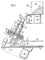
- FIG. 1 shows a simplified representation, partly in section Drawn first embodiment of the invention
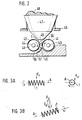
- Figure 2 is a simplified side view of another embodiment
- the device for separating coil springs 1 shown in FIG. 1 has two parallel surfaces 2, 3 with at least approximately the same surface properties.
- the spacing of the surfaces 2, 3 from one another is predetermined by the largest outer diameter of the helical springs 1 introduced.
- the length of the springs is larger than their diameter.
- the surfaces 2, 3 are formed by lengths 4, 5 with high coefficients of friction, for example made of rubber or a suitable plastic.
- the surfaces 2, 3 perform relative movements to one another, which are transmitted by static friction to the springs 1 located between them and cause them to cause rolling movements to be separated.
- the working gap formed by the distance between the plane-parallel surface 2, 3 for receiving the springs 1 is designated by 6.
- the coverings 4, 5 are attached to the mutually facing, plane-parallel surfaces of two plates 7, 8.
- these plates 7, 8 are designed as coaxially mounted, rotating disks or rotating bodies.
- Each disc has a shaft 9 or 10.
- the shaft 9 of the lower disc 7 is mounted in a bushing 11, which is fastened by means of an angle piece 12 on a support frame with a table top 13.
- the bearing bush for the hollow shaft 10 of the upper disk 8 bears the reference number 14. It can also be fastened to the table top 13 and allows the shaft 10 to move in the axial direction apart from the rotation of a predetermined size.
- the two disks 7, 8 are driven by an electric motor 15 attached to the underside of the table top 13 via two gear trains 16, 17 indicated by dashed lines.
- the gear train 17 leading to the hollow shaft 10 contains a reversing gear 18, which causes the two Shafts with their discs have opposite directions of rotation (arrows 19 and 20).
- a compression spring 22 is pushed onto the shaft 10. One end of this spring is supported on the lower end face of the bearing bush 14. The other spring end rests on the plate 8.
- the spring 22 places the axially movable hollow shaft 10 with a collar 21 anchored in it against an adjusting disk 23, with which the size of the working gap 6 can be optimized. In the axial position of the shaft 10 specified by the disk 23, the distance between the friction surfaces 2, 3 from one another is slightly smaller than the largest outer diameter of the springs 1.
- a bunker 28 is provided, which is closed on all sides by a side wall 30, with the exception of an opening opening into an obliquely downwardly directed feed trough 29, but is open at the top.
- the bunker 28 forms a store for the pile 31 consisting of springs 1.
- the bunker can be placed on a linear conveyor 32, so that the pile 31 defined in its geometry is pushed forward cyclically onto the conveyor chute 29.
- the trough 29 ends above a funnel 33, the lower end of which is enclosed by the hollow shaft 10.
- the funnel 33 is attached to a fixed support 34.
- the interlocked springs 1 fall through the hollow shaft 10 into the working gap 6 formed by the surfaces 2, 3 between the friction linings 4, 5.
- the two plates 7, 8 are of a collecting and discharge plate 35 covering the working gap 6 towards the outside for the isolated Fe enclosed 1, the bottom 36 of which lies below the plate 7 has an ejection opening in the region of a conveyor belt 37, the deflection roller of which is designated by 38.
- the working gap 6 is inclined to the horizontal in the direction of the conveyor belt 37 by appropriate arrangement of the plates 7, 8. This has the advantage that gravity helps to bring the isolated springs 1 through the ejection opening of the collecting and discharge plate 35 onto the conveyor belt 37. Deviating from this, the friction surfaces 2, 3 and their supports could also assume a vertical or horizontal position in space.
- the size of the force determined by the spring 22 with which the friction surface 3 presses on the confused springs 1 depends on the strength and geometry of the springs. Tapered and weak springs are subjected to low forces, while correspondingly high pressure forces are required to separate strong, central springs. It is conceivable to optimize the pressure force for separating springs of different strengths by using different pressure springs 22.
- the relative movement of the friction surfaces 2, 3 in FIG. 1 is achieved in that the plates 7, 8 rotate in opposite directions, the axes of rotation of the plates being arranged coaxially to one another. Deviating from this, the rotary movement of one or both plates could be superimposed on an eccentric movement which supports the separation of the springs 1. It would also be possible to rotate the plates in the same direction of rotation but at different angular speeds. In addition, the relative movement of the plates can take place continuously or discontinuously with negative or positive acceleration. Furthermore, at least one friction surface could only perform a purely eccentric movement as the sole movement. Which of these types is used in individual cases does not depend last of all on the outer contour and the strength of the springs to be unraveled. A particularly simple design is that only one plate 7 or 8 is rotatably and / or movably arranged along an eccentric path, while the other plate is stationary.
- plates could also be used as carriers of the friction surfaces, which perform translational longitudinal and / or transverse movements parallel to the working gap.
- the relative movement of such plates could also take place continuously or discontinuously with positive or negative acceleration and could also be supplemented by cyclical lifting movements of a plate.
- a relative movement, which leads to spring separation, can be transmitted not only by flat but also by curved friction surfaces.
- An embodiment of such a device is shown schematically in Figure 2.
- Two cylindrical rollers 39, 40 rotating in opposite directions are each provided with a friction lining 41 or 42 on their outer circumference.
- the rollers 39, 40 each sit on a drive shaft 43 or 44, which are aligned parallel to one another.
- the cylindrical surfaces of the rollers formed by the friction linings 41, 42 have a predetermined distance from one another which corresponds to the largest outside diameter of the springs to be separated and forms the working gap 45 of the device.
- a bunker 47 is attached to a carrier 46, which forms a storage space for the parts pile 48 to be untangled.
- the carrier 46 can be coupled to a vibrator device, not shown, which vibrates the bunker 47.
- the material to be untangled emerges from a narrow opening 49 on the underside of the bunker in such a way that it falls between the two rollers 41, 42.
- the springs 1 After going through the ar beitsspalts 45 the springs 1 enter a separating channel 50 which is formed by the outer circumference of the roller 40 and by a surface 51 fixed to the device and is a continuation of the working gap 45.
- a separating channel 50 which is formed by the outer circumference of the roller 40 and by a surface 51 fixed to the device and is a continuation of the working gap 45.
- three rollers could also be used, the axes of which form the corner points of an equilateral triangle.
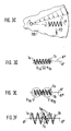
- the springs 1 In the case of rotating or eccentrically moving friction surfaces, the springs 1 must constantly absorb lateral forces, since the direction of the circumferential force always changes. In addition, the different peripheral speed of the friction surfaces (depending on their radius) contributes to the fact that the individual windings of a spring 1 have different friction ratios, i.e. have different power transmission. The result is the resultant forces, each of which gives the springs a preferred rolling direction indicated by an arrow 52.
- Twisted and hooked springs 1a, 1b will roll apart due to their different resulting rolling direction.
- the different directions result in parallel rolling axes A 'and A ⁇ of the springs 1a, 1b by the different inclusion of Lateral and circumferential forces (depending on the respective support conditions) per turn and confused spring (Figure 3E) or through non-parallel rolling axes A 'or A ⁇ of the confused springs ( Figure 3D).
- the resulting directions of movement of the springs are indicated in FIGS. 3D and 3E by two arrows R 1a and R 1b .
- the lateral and circumferential forces during rolling and the rolling process itself tension and deform the tangled springs in such a way that intertwined turns try to separate.
- the springs are deformed differently within the confusion.
- the turns spacing become irregular.
- Increased frictional forces occur between the turns of the jammed springs (arrows F N and F R in FIG. 3F), the components of which loosen and separate the springs.
- the braced area is enclosed by a circle in FIG. 3F.
- the confusion of the springs is prevented by the different rolling directions of the individual springs and by the defined distance between the friction surfaces.
Landscapes
- Engineering & Computer Science (AREA)
- Mechanical Engineering (AREA)
- Feeding Of Articles To Conveyors (AREA)
Applications Claiming Priority (2)
| Application Number | Priority Date | Filing Date | Title |
|---|---|---|---|
| DE19873733589 DE3733589C1 (de) | 1987-10-05 | 1987-10-05 | Vorrichtung zum Vereinzeln von Wirrteilen |
| DE3733589 | 1987-10-05 |
Publications (1)
| Publication Number | Publication Date |
|---|---|
| EP0310833A1 true EP0310833A1 (fr) | 1989-04-12 |
Family
ID=6337626
Family Applications (1)
| Application Number | Title | Priority Date | Filing Date |
|---|---|---|---|
| EP19880115104 Withdrawn EP0310833A1 (fr) | 1987-10-05 | 1988-09-15 | Procédé pour isoler des pièces emmêlées |
Country Status (2)
| Country | Link |
|---|---|
| EP (1) | EP0310833A1 (fr) |
| DE (1) | DE3733589C1 (fr) |
Cited By (1)
| Publication number | Priority date | Publication date | Assignee | Title |
|---|---|---|---|---|
| CN108857384A (zh) * | 2018-07-02 | 2018-11-23 | 苏州富强科技有限公司 | 一种取料机构及装配组件自动装配装置 |
Families Citing this family (2)
| Publication number | Priority date | Publication date | Assignee | Title |
|---|---|---|---|---|
| DE10133805B4 (de) * | 2001-07-11 | 2005-09-15 | Braun Gmbh | Einrichtung zum Zuführen von Bauteilen zu einer Montagestation |
| DE102008054106B4 (de) | 2008-10-31 | 2010-07-22 | Gottfried Wilhelm Leibniz Universität Hannover | Verfahren und Vorrichtung zum Vereinzeln von Werkstücken |
Citations (2)
| Publication number | Priority date | Publication date | Assignee | Title |
|---|---|---|---|---|
| FR366418A (fr) * | 1906-05-19 | 1906-10-04 | Saechsische Schrauben & Mutter | Dispositif pour amener des pièces à travailler de forme régulière à l'endroit de travail |
| DE1288007B (fr) * | 1969-01-23 |
Family Cites Families (3)
| Publication number | Priority date | Publication date | Assignee | Title |
|---|---|---|---|---|
| AT336498B (de) * | 1975-05-20 | 1977-05-10 | Sticht Walter | Vorrichtung zum vereinzelnen von teilen |
| US4078994A (en) * | 1976-04-29 | 1978-03-14 | Hazelwood Sr John E | Apparatus for separating entangled parts |
| DE2851811A1 (de) * | 1978-06-13 | 1980-06-04 | Hans Prof Dr Ing Kettner | Vorrichtung zum entwirren von verhaengenden teilen |
-
1987
- 1987-10-05 DE DE19873733589 patent/DE3733589C1/de not_active Expired
-
1988
- 1988-09-15 EP EP19880115104 patent/EP0310833A1/fr not_active Withdrawn
Patent Citations (2)
| Publication number | Priority date | Publication date | Assignee | Title |
|---|---|---|---|---|
| DE1288007B (fr) * | 1969-01-23 | |||
| FR366418A (fr) * | 1906-05-19 | 1906-10-04 | Saechsische Schrauben & Mutter | Dispositif pour amener des pièces à travailler de forme régulière à l'endroit de travail |
Cited By (2)
| Publication number | Priority date | Publication date | Assignee | Title |
|---|---|---|---|---|
| CN108857384A (zh) * | 2018-07-02 | 2018-11-23 | 苏州富强科技有限公司 | 一种取料机构及装配组件自动装配装置 |
| CN108857384B (zh) * | 2018-07-02 | 2024-02-06 | 苏州富强科技有限公司 | 一种取料机构及装配组件自动装配装置 |
Also Published As
| Publication number | Publication date |
|---|---|
| DE3733589C1 (de) | 1989-04-06 |
Similar Documents
| Publication | Publication Date | Title |
|---|---|---|
| DE2462121A1 (de) | Rundwebstuhl | |
| DE2301653C3 (de) | Straßenbehandlungsgerät zur Verbesserung der Griffigkeit eines Strafien- | |
| DE2637851A1 (de) | Vorrichtung zum separieren von spritzgut und angussteilen o.dgl. | |
| DE60009016T2 (de) | Vorrichtung zur mechanischen Reinigung von Draht für die Herstellung von gezogenen Metalldrähten | |
| DE3733589C1 (de) | Vorrichtung zum Vereinzeln von Wirrteilen | |
| DE4445515C2 (de) | Siebeinrichtung | |
| WO1995003896A1 (fr) | Procede et dispositif permettant de separer des materiaux d'un melange de solides | |
| DE1176581B (de) | Verfahren und Vorrichtung zum Sortieren, insbesondere von mineralischem Material | |
| CH653314A5 (de) | Fadenliefervorrichtung fuer textilmaschinen. | |
| DE1652347A1 (de) | Verfahren und Vorrichtung zum gleichmaessig verteilten Zufuehren von Flockmaterial bei elektrostatischen Beflockungseinrichtungen | |
| EP0218575A2 (fr) | Dispositif de tamisage | |
| DE6905064U (de) | Siebanlage. | |
| DE3245456A1 (de) | Sichtmaschine fuer korn- oder samenartiges erntegut | |
| DE2532493A1 (de) | Verfahren und vorrichtung zur nassmagnetischen aufbereitung von feinkoernigem feststoff | |
| DE3011351A1 (de) | Rotorenschere fuer die abfallzerkleinerung | |
| DE102006017138B4 (de) | Vorrichtung zum Klassieren eines Stoffgemisches | |
| DE3018741C2 (fr) | ||
| EP0009692A1 (fr) | Tamis à bandes de criblage circulant autour de poulies de renvoi | |
| DE2331995A1 (de) | Verfahren und vorrichtung zum verspinnen von losen fasern | |
| DE3605683A1 (de) | Foerdereinrichtung zum foerdern eines klebrigen bandartigen objektes | |
| DE2638353A1 (de) | Vorrichtung zur vorformung von faservliesen | |
| DE901401C (de) | Verfahren und Vorrichtung zum Trennen und Sichten von im wesentlichen sphaerischen Koerpern in verschiedene Groessengruppen | |
| DE3728068A1 (de) | Fachbildungseinrichtung fuer dreherbindung | |
| AT61767B (de) | Reinigungsvorrichtung mit endlosem Förderband. | |
| EP0932165A1 (fr) | Dispositif de fabrication d'un câblage |
Legal Events
| Date | Code | Title | Description |
|---|---|---|---|
| PUAI | Public reference made under article 153(3) epc to a published international application that has entered the european phase |
Free format text: ORIGINAL CODE: 0009012 |
|
| AK | Designated contracting states |
Kind code of ref document: A1 Designated state(s): CH DE FR GB IT LI |
|
| 17P | Request for examination filed |
Effective date: 19890828 |
|
| STAA | Information on the status of an ep patent application or granted ep patent |
Free format text: STATUS: THE APPLICATION IS DEEMED TO BE WITHDRAWN |
|
| 18D | Application deemed to be withdrawn |
Effective date: 19910403 |