EP0310874A2 - Procédé amélioré pour examiner des tuyaux - Google Patents
Procédé amélioré pour examiner des tuyaux Download PDFInfo
- Publication number
- EP0310874A2 EP0310874A2 EP88115556A EP88115556A EP0310874A2 EP 0310874 A2 EP0310874 A2 EP 0310874A2 EP 88115556 A EP88115556 A EP 88115556A EP 88115556 A EP88115556 A EP 88115556A EP 0310874 A2 EP0310874 A2 EP 0310874A2
- Authority
- EP
- European Patent Office
- Prior art keywords
- film
- radiation source
- pipe
- attached
- pipe clamp
- Prior art date
- Legal status (The legal status is an assumption and is not a legal conclusion. Google has not performed a legal analysis and makes no representation as to the accuracy of the status listed.)
- Withdrawn
Links
Images


Classifications
-
- G—PHYSICS
- G01—MEASURING; TESTING
- G01N—INVESTIGATING OR ANALYSING MATERIALS BY DETERMINING THEIR CHEMICAL OR PHYSICAL PROPERTIES
- G01N23/00—Investigating or analysing materials by the use of wave or particle radiation, e.g. X-rays or neutrons, not covered by groups G01N3/00 – G01N17/00, G01N21/00 or G01N22/00
- G01N23/02—Investigating or analysing materials by the use of wave or particle radiation, e.g. X-rays or neutrons, not covered by groups G01N3/00 – G01N17/00, G01N21/00 or G01N22/00 by transmitting the radiation through the material
- G01N23/04—Investigating or analysing materials by the use of wave or particle radiation, e.g. X-rays or neutrons, not covered by groups G01N3/00 – G01N17/00, G01N21/00 or G01N22/00 by transmitting the radiation through the material and forming images of the material
-
- G—PHYSICS
- G01—MEASURING; TESTING
- G01N—INVESTIGATING OR ANALYSING MATERIALS BY DETERMINING THEIR CHEMICAL OR PHYSICAL PROPERTIES
- G01N23/00—Investigating or analysing materials by the use of wave or particle radiation, e.g. X-rays or neutrons, not covered by groups G01N3/00 – G01N17/00, G01N21/00 or G01N22/00
- G01N23/02—Investigating or analysing materials by the use of wave or particle radiation, e.g. X-rays or neutrons, not covered by groups G01N3/00 – G01N17/00, G01N21/00 or G01N22/00 by transmitting the radiation through the material
- G01N23/06—Investigating or analysing materials by the use of wave or particle radiation, e.g. X-rays or neutrons, not covered by groups G01N3/00 – G01N17/00, G01N21/00 or G01N22/00 by transmitting the radiation through the material and measuring the absorption
- G01N23/083—Investigating or analysing materials by the use of wave or particle radiation, e.g. X-rays or neutrons, not covered by groups G01N3/00 – G01N17/00, G01N21/00 or G01N22/00 by transmitting the radiation through the material and measuring the absorption the radiation being X-rays
-
- G—PHYSICS
- G01—MEASURING; TESTING
- G01N—INVESTIGATING OR ANALYSING MATERIALS BY DETERMINING THEIR CHEMICAL OR PHYSICAL PROPERTIES
- G01N23/00—Investigating or analysing materials by the use of wave or particle radiation, e.g. X-rays or neutrons, not covered by groups G01N3/00 – G01N17/00, G01N21/00 or G01N22/00
- G01N23/02—Investigating or analysing materials by the use of wave or particle radiation, e.g. X-rays or neutrons, not covered by groups G01N3/00 – G01N17/00, G01N21/00 or G01N22/00 by transmitting the radiation through the material
- G01N23/06—Investigating or analysing materials by the use of wave or particle radiation, e.g. X-rays or neutrons, not covered by groups G01N3/00 – G01N17/00, G01N21/00 or G01N22/00 by transmitting the radiation through the material and measuring the absorption
- G01N23/18—Investigating the presence of flaws defects or foreign matter
Definitions
- the invention relates to an improved method for testing pipelines at support points and in the area of pipe clamps.
- Corrosion can occur especially at the support points, such as on pipe bridges and under pipe clamps. Corrosion can also occur, for example, under the existing paint and on the inside surface of the pipes in the area of the support points and pipe clamps.
- the pipes must be raised by at least 100 mm for measurements at support points and made testable at the points to be examined by grinding.
- a further disadvantage of the test methods mentioned is the risk that the lines will break through at the corroded locations when lifting. This can also be done very easily if the lifting takes place, for example, by driving wedges between the pipes and the support device.
- Line pipes are often led over pipe bridges or other cross beams and rest on them at certain points. According to the present invention, the contact area on the inside and outside of the pipe can be reliably checked for whether there is corrosion or other wear in this area.
- Pipes are often also fastened with pipe clamps. This can be done by hanging pipe clamps, by pipe clamps attached to the side or under the pipeline.
- the surface of the pipe lying under the pipe clamp can only be examined by temporarily securing the pipe in a different way and then removing the pipe clamp.
- the present invention offers a very significant improvement, namely that the area lying under the pipe clamp can be examined by means of both tangential and diagonal radiation without having to carry out the preparatory work mentioned above.
- FIGS. 1-6 Arrangements according to the invention are shown by way of example in FIGS. 1-6.
- ⁇ and X-ray sources for corrosion tests are known per se.
- ⁇ -radiation sources these are usually small radioactive rods a few millimeters in diameter made of a radioactive material such as iridium or cobalt, but other radioactive materials can also be used.
- the radiation source itself is housed in a working and transport container which surrounds it, with the radiation source usually being pushed out of the container, for example with the aid of a remote control, through an extension hose or, for example, through an extension tube into the radiation position, for example the extension tip, during radiographic examinations.
- the encased radiation source is advantageously brought into a fixed position on a pipe side and laterally to the support device with a holder.
- a film is attached on the opposite side, usually also with a fixed holder, in such a way that the rays of the radiation source can produce an image of sufficient blackening on the film.
- X-ray films can be used as films.
- An X-ray film / amplifier film combination is preferred.
- the exposure times can be reduced by at least 80% based on the usual values. This has the advantageous effect that the radiation exposure of the test personnel is only low, since it is limited only for a short time and only to a small space.
- the beams can also be used, such as, for example, all devices used for radioactive radiation, for example devices operating according to the Geiger counter principle. It is essential to the invention that the beams strike the point to be tested both tangentially and diagonally under the specified conditions.
- the radiation sources which can be used according to the invention can have different radiation activities.
- a ⁇ radiation source is preferred which can also have different activity.
- the radiation source which is usually located in a container as described, is positioned in such a way, for example with a holder on the support device, but also with any other holders that the central connecting line between the radiation source and film with the pipeline's longitudinal axis forms an angle of 30 ° to 75 °.
- the radiation source must be up to 0.5 D below the contact surface and up to 1 D above the contact surface.
- the radiation source is preferably located up to 0.25 D below up to 0.5 D above the contact surface, and it can also be located centrally at the level of the contact. D is the diameter of the radiation source.
- the lower edge of the radiation source can be up to a maximum of 0.8 mm, preferably 0.4 mm, below the contact surface.
- the lower edge can be up to a maximum of 1.6 mm above the contact surface, preferably 0.8 mm above the height of the contact surface.
- the radiation source is positioned in such a position relative to the area to be tested that the center of the radiator is located up to 25 D below and up to 25 D above the pipe line / pipe clamp at the point to be tested, preferably up to 10 D below to 10 D above this line, where D is the diameter of the radiator.
- the radiation source can advantageously be located centrally at the level of this line and close to the support point.
- the area under the pipe clamp can be checked around the entire pipe without the above-mentioned preparatory activities being necessary.
- the distance from the radiation source and from the film to the intersection between the pipeline and the support surface, or the contact point between the outer pipe wall and the inner pipe clamp surface can be a maximum of 100 cm, preferably ⁇ 50 cm, for the radiation source and / or film, with the shortest possible distances preferred.
- the radiation source and film can therefore be at the specified height in a segment with a radius of 100 cm or less.
- the film is applied in such a way that the blackening is sufficient to identify the areas of corrosion.
- the film is preferably applied perpendicular to the central connecting line between the radiation source and the center of the X-ray film.
- Two radiographs are preferably taken. In principle, however, several recordings can also be made. It must be taken into account that a single exposure from only one direction often does not provide a result that can be reliably evaluated, except in cases in which the contact area is sufficiently small or the contact device is very narrow. The same applies to testing in the area of pipe clamps, whereby a single mount is sufficient only if the pipe clamps are sufficiently narrow.
- the preferred procedure is to take the radiation source and film on the opposite side to the support device or to the pipe clamp area to be tested, but on the same side of the pipeline or on the opposite side of the second picture Pipe and on the opposite side of the support device or to the pipe clamp area to be tested in position.
- the particularly advantageous effect of the method according to the invention in the support area is based on the fact that there is no need to lift the pipelines from the support device.
- the pipeline does not need to be flushed, nor do the pipeline flanges have to be opened, nor are dummy covers to be installed.
- the test according to the invention has no effect on the operation of the plant (s) with which the pipeline is connected, ie the test can be carried out with the plant in operation.
- the investigations by the applicant have shown that pipelines with an inner diameter of 30 mm to 300 mm, preferably 50 mm to 250 mm, can be tested very precisely.
- the thickness of the pipe wall is of no importance for the test for external corrosion at support points or under pipe clamps, since the extent of the corrosion can be calculated from the film recordings. However, if the corrosion is determined in such a way that one wants to measure the extent of the corrosion directly on the film recording, for example with a caliper, the contour of the inner pipe wall must be recognizable.
- the pipe wall should not be thicker than 20 mm, the lower limit of the wall thickness is generally not less than 1 mm.
- the pipe wall thickness should preferably be 1 - 12 mm.
- the pipe wall thickness should also preferably be 1 - 12 mm. It is generally known that the quality of ⁇ radiographs also depends on the medium flowing through the pipes. To a certain or comparable extent, this also applies to measurements according to the present invention.
- the tube materials can be any materials, in particular the usual materials made of iron, unalloyed and alloyed steel, but also other metals or alloys.
- pipe insulation need not be removed for testing. Furthermore, cleaning, grinding, removing paint and the like are not required.
- the present invention not only the support area and the pipe clamp area itself, but also its immediate vicinity can be checked for corrosion.
- the thickness of the tube can be reliably determined from the exposed X-ray film (s) by relating the distances measured on site from the radiator to the center of the tube and from the radiator to the X-ray film in relation to the actual wall thickness and the wall thickness shown. Surface erosion, trough and pitting and other forms of corrosion can be reliably determined according to the invention.
- (1) represents a 250 mm pipe
- (3) is a wide
- (5) are a radiation source
- (6) - (9) are ( X-ray) films.
- the specified angles are formed by the longitudinal axis of the pipeline and the central connection between the radiation source and the (X-ray) film center.
- the second image recording device in which the radiation source and (X-ray) film on the opposite overlying side of the support device.
- FIG. 3 shows the position of the radiation source in the described segment at a distance of 100 cm from the intersection (10).
- Insulated pipes are shown in FIGS. 4 and 5.
- the pipelines rest on the support devices.
- Corresponding segments are cut out of the insulation at the support points. (1) each represents the support device, (2) the insulation, (3) the pipeline, (4) the radiation source and (5) the film or other receiving device attached behind the insulated pipeline.
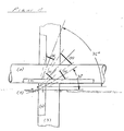
- FIG. 6 shows a typical corrosion test under a pipe clamp.
- (1) represents the pipeline in the area of the area to be tested, (2) the pipe clamp, (3) the radiation source.
- (4) identifies the X-ray film.
- (5) is the opening angle of the beam in the plane of the pipe longitudinal direction.
- (6) represents the angle of the central ⁇ -ray in the direction of the film center to the pipe longitudinal direction.
Landscapes
- Health & Medical Sciences (AREA)
- Biochemistry (AREA)
- Physics & Mathematics (AREA)
- Life Sciences & Earth Sciences (AREA)
- Chemical & Material Sciences (AREA)
- Analytical Chemistry (AREA)
- General Health & Medical Sciences (AREA)
- General Physics & Mathematics (AREA)
- Immunology (AREA)
- Pathology (AREA)
- Toxicology (AREA)
- Analysing Materials By The Use Of Radiation (AREA)
- Length-Measuring Devices Using Wave Or Particle Radiation (AREA)
- Investigating Or Analyzing Materials By The Use Of Electric Means (AREA)
Applications Claiming Priority (2)
| Application Number | Priority Date | Filing Date | Title |
|---|---|---|---|
| DE3732514 | 1987-09-26 | ||
| DE19873732514 DE3732514A1 (de) | 1987-09-26 | 1987-09-26 | Verbessertes verfahren zur pruefung von rohrleitungen |
Publications (2)
| Publication Number | Publication Date |
|---|---|
| EP0310874A2 true EP0310874A2 (fr) | 1989-04-12 |
| EP0310874A3 EP0310874A3 (fr) | 1990-05-16 |
Family
ID=6336971
Family Applications (1)
| Application Number | Title | Priority Date | Filing Date |
|---|---|---|---|
| EP88115556A Withdrawn EP0310874A3 (fr) | 1987-09-26 | 1988-09-22 | Procédé amélioré pour examiner des tuyaux |
Country Status (11)
| Country | Link |
|---|---|
| EP (1) | EP0310874A3 (fr) |
| AU (1) | AU2275488A (fr) |
| BR (1) | BR8804994A (fr) |
| CS (1) | CS636688A3 (fr) |
| DD (1) | DD281657A5 (fr) |
| DE (1) | DE3732514A1 (fr) |
| ES (1) | ES2007593A4 (fr) |
| GR (1) | GR890300070T1 (fr) |
| NO (1) | NO884224L (fr) |
| NZ (1) | NZ226327A (fr) |
| ZA (1) | ZA887028B (fr) |
Cited By (3)
| Publication number | Priority date | Publication date | Assignee | Title |
|---|---|---|---|---|
| WO1990004168A1 (fr) * | 1988-10-11 | 1990-04-19 | Dea Mineraloel Ag | Procede perfectionne pour le controle de canalisations |
| WO2010033265A1 (fr) * | 2008-09-19 | 2010-03-25 | Analogic Corporation | Inspection de conduite |
| WO2017109295A1 (fr) * | 2015-12-23 | 2017-06-29 | Outotec (Finland) Oy | Procédé et agencement de suivi d'un processus hydrométallurgique |
Families Citing this family (1)
| Publication number | Priority date | Publication date | Assignee | Title |
|---|---|---|---|---|
| DE4035412A1 (de) * | 1990-11-07 | 1992-05-14 | Siemens Ag | Verfahren und vorrichtung zur gammaspektrometrischen autoradiographie |
Family Cites Families (6)
| Publication number | Priority date | Publication date | Assignee | Title |
|---|---|---|---|---|
| US3521059A (en) * | 1967-03-15 | 1970-07-21 | Arabian American Oil Co | Apparatus for radiographing pipes having a film marker means associated therewith |
| IL66249A (en) * | 1982-07-07 | 1985-12-31 | Rochman Zvi Henri | Safety lock with automatic bolting |
| US4567012A (en) * | 1982-07-12 | 1986-01-28 | Combustion Engineering, Inc. | Dual isotope method to radiograph structures in nuclear steam supply systems |
| FR2554592A1 (fr) * | 1983-11-09 | 1985-05-10 | Coubard Bernard | Support pour controle non destructif, notamment gammagraphique |
| HU190197B (en) * | 1983-12-05 | 1986-08-28 | Kohaszati Gyarepitoe Vallalat,Hu | Method and device for testing quality of the welds by videoradiography |
| SE8404248L (sv) * | 1984-08-27 | 1985-10-21 | Stig Dahn | Sett att medelst rontgenstralning detektera inhomogeniteter i skarvar mellan och i isoleringen i fjerrvermeror samt anordning att utfora settet |
-
1987
- 1987-09-26 DE DE19873732514 patent/DE3732514A1/de active Granted
-
1988
- 1988-09-20 ZA ZA887028A patent/ZA887028B/xx unknown
- 1988-09-22 ES ES88115556T patent/ES2007593A4/es active Pending
- 1988-09-22 EP EP88115556A patent/EP0310874A3/fr not_active Withdrawn
- 1988-09-23 DD DD88320087A patent/DD281657A5/de not_active IP Right Cessation
- 1988-09-23 AU AU22754/88A patent/AU2275488A/en not_active Abandoned
- 1988-09-23 NO NO88884224A patent/NO884224L/no unknown
- 1988-09-26 NZ NZ226327A patent/NZ226327A/xx unknown
- 1988-09-26 CS CS886366A patent/CS636688A3/cs unknown
- 1988-09-27 BR BR888804994A patent/BR8804994A/pt unknown
-
1989
- 1989-09-29 GR GR89300070T patent/GR890300070T1/el unknown
Cited By (4)
| Publication number | Priority date | Publication date | Assignee | Title |
|---|---|---|---|---|
| WO1990004168A1 (fr) * | 1988-10-11 | 1990-04-19 | Dea Mineraloel Ag | Procede perfectionne pour le controle de canalisations |
| WO2010033265A1 (fr) * | 2008-09-19 | 2010-03-25 | Analogic Corporation | Inspection de conduite |
| US8759780B2 (en) | 2008-09-19 | 2014-06-24 | Analogic Corporation | Pipeline inspection |
| WO2017109295A1 (fr) * | 2015-12-23 | 2017-06-29 | Outotec (Finland) Oy | Procédé et agencement de suivi d'un processus hydrométallurgique |
Also Published As
| Publication number | Publication date |
|---|---|
| AU2275488A (en) | 1989-04-13 |
| NO884224L (no) | 1989-03-28 |
| CS636688A3 (en) | 1992-03-18 |
| NZ226327A (en) | 1991-03-26 |
| GR890300070T1 (en) | 1989-09-29 |
| EP0310874A3 (fr) | 1990-05-16 |
| NO884224D0 (no) | 1988-09-23 |
| DE3732514A1 (de) | 1989-04-13 |
| ES2007593A4 (es) | 1989-07-01 |
| BR8804994A (pt) | 1989-05-02 |
| DD281657A5 (de) | 1990-08-15 |
| ZA887028B (en) | 1989-07-26 |
| DE3732514C2 (fr) | 1993-01-28 |
Similar Documents
| Publication | Publication Date | Title |
|---|---|---|
| DE3810906C2 (de) | Verfahren zur Ermittlung von in Oberflächen von keramischen Drehkörpern entstandenen Fehlern mit Hilfe von Ultraschallwellen und Vorrichtung zur Durchführung des Verfahrens | |
| DE3686166T2 (de) | Verfahren und vorrichtung zur kennzeichnung der fehler in leitungen. | |
| DE3834586A1 (de) | Verbessertes verfahren zur pruefung von rohrleitungen | |
| DE69027538T2 (de) | Verfahren zum messen von defekten in einer pipeline | |
| DE2607485A1 (de) | Verfahren zum einstellen von einschallwinkeln bei der us-pruefung von rohren, baendern und blechen | |
| DE4303091A1 (fr) | ||
| DE1473661A1 (de) | Vorrichtung zur Ermittlung von Fehlstellen in heissen Metallen mittels Ultraschall | |
| DE2831311C2 (de) | Vorrichtung zur Ermittlung innerer Körperstrukturen mittels Streustrahlung | |
| EP0310874A2 (fr) | Procédé amélioré pour examiner des tuyaux | |
| DE2015606B2 (de) | Vorrichtung zum pruefen eines bandfoermigen materials | |
| DE2853305A1 (de) | Korrosionsmessvorrichtung fuer radioaktive komponenten | |
| DE3119287C2 (fr) | ||
| DE2838891A1 (de) | Verfahren zum feststellen von leckstellen in rohrleitungen | |
| DE3412108A1 (de) | Verfahren zum optischen bestimmen der oberflaechenbeschaffenheit von festkoerpern | |
| DE1773075A1 (de) | Ultraschallpruefverfahren fuer Ultraschallwinkelstrahl-Pruefgeraete mit Rueckstrahlblock | |
| DE1949586C3 (de) | Vorrichtung zur Ultraschall Werkstoffprüfung von Stahlplatten | |
| DE2200651A1 (de) | Durchstrahlungs-Dickenmessanlage | |
| DE2817742C2 (de) | Verfahren und Vorrichtung zum Bestimmen technologischer Kennwerte | |
| DE19843397C1 (de) | Computertomographisches Verfahren und Computertomograph zur Prüfung eine Gegenstandes | |
| DE752037C (de) | Einrichtung zur roentgenographischen Untersuchung von Rohrleitungen | |
| DE1648517C3 (de) | Verfahren zum Auffinden von Oberflächenrissen in Stangen, Knüppeln, Rohren und ähnlichen Werkstücken mit Kanten aufweisendem Querschnitt | |
| EP0019826B1 (fr) | Appareil pour la représentation de coupes par tomographie transversale | |
| WO1986003005A1 (fr) | Procede de le controle non destructif de pieces en materiau non homogene | |
| DE2236221C3 (de) | Optisches Verfahren zur Oberflächenprüfung von Werkstücken, insbesondere zur Erfassung der Aufrauhung der Werkstückoberfläche von Brennelement-Hüllrohren | |
| DD267568A1 (de) | Verfahren zur zerstoerungsfreien pruefung und bewertung von materialfehlern in werkstuecken |
Legal Events
| Date | Code | Title | Description |
|---|---|---|---|
| PUAI | Public reference made under article 153(3) epc to a published international application that has entered the european phase |
Free format text: ORIGINAL CODE: 0009012 |
|
| 17P | Request for examination filed |
Effective date: 19880930 |
|
| AK | Designated contracting states |
Kind code of ref document: A2 Designated state(s): AT BE CH DE ES FR GB GR IT LI LU NL SE |
|
| ITCL | It: translation for ep claims filed |
Representative=s name: SOCIETA' ITALIANA BREVETTI S.P.A. |
|
| TCNL | Nl: translation of patent claims filed | ||
| EL | Fr: translation of claims filed | ||
| PUAL | Search report despatched |
Free format text: ORIGINAL CODE: 0009013 |
|
| AK | Designated contracting states |
Kind code of ref document: A3 Designated state(s): AT BE CH DE ES FR GB GR IT LI LU NL SE |
|
| RAP1 | Party data changed (applicant data changed or rights of an application transferred) |
Owner name: DEA MINERALOEL AKTIENGESELLSCHAFT |
|
| 17Q | First examination report despatched |
Effective date: 19910909 |
|
| RAP1 | Party data changed (applicant data changed or rights of an application transferred) |
Owner name: HEISKEL, GEORG |
|
| STAA | Information on the status of an ep patent application or granted ep patent |
Free format text: STATUS: THE APPLICATION IS DEEMED TO BE WITHDRAWN |
|
| 18D | Application deemed to be withdrawn |
Effective date: 19930211 |