EP0310945A2 - Blindage pour connecteur électrique - Google Patents
Blindage pour connecteur électrique Download PDFInfo
- Publication number
- EP0310945A2 EP0310945A2 EP88116099A EP88116099A EP0310945A2 EP 0310945 A2 EP0310945 A2 EP 0310945A2 EP 88116099 A EP88116099 A EP 88116099A EP 88116099 A EP88116099 A EP 88116099A EP 0310945 A2 EP0310945 A2 EP 0310945A2
- Authority
- EP
- European Patent Office
- Prior art keywords
- spring
- groove
- plug
- receptacle
- elastomeric member
- Prior art date
- Legal status (The legal status is an assumption and is not a legal conclusion. Google has not performed a legal analysis and makes no representation as to the accuracy of the status listed.)
- Withdrawn
Links
Images
Classifications
-
- H—ELECTRICITY
- H01—ELECTRIC ELEMENTS
- H01R—ELECTRICALLY-CONDUCTIVE CONNECTIONS; STRUCTURAL ASSOCIATIONS OF A PLURALITY OF MUTUALLY-INSULATED ELECTRICAL CONNECTING ELEMENTS; COUPLING DEVICES; CURRENT COLLECTORS
- H01R13/00—Details of coupling devices of the kinds covered by groups H01R12/70 or H01R24/00 - H01R33/00
- H01R13/648—Protective earth or shield arrangements on coupling devices, e.g. anti-static shielding
- H01R13/658—High frequency shielding arrangements, e.g. against EMI [Electro-Magnetic Interference] or EMP [Electro-Magnetic Pulse]
- H01R13/6581—Shield structure
- H01R13/6582—Shield structure with resilient means for engaging mating connector
- H01R13/6583—Shield structure with resilient means for engaging mating connector with separate conductive resilient members between mating shield members
Definitions
- the present invention relates generally to an electrical connector and, more particularly, to a electro-magnetic and radio frequency interference (EMI/RFI) shield for an electrical connector.
- EMI/RFI electro-magnetic and radio frequency interference
- a newly proposed U.S. Government specification requires for EMI/FRI shielding of an electrical connector to be in the range of 85-90 dB shielding effectiveness.
- a common EMI/RFI shield that has been used in the past to meet prior Government specifications is similar to that disclosed in the aforementioned patent 4,106,839.
- the shield comprises a stamped and formed metal spring in which fingers extending laterally from an annular band are reversely folded with the outer ends of the fingers resiliently engaging the inside surface of the receptacle shell.
- the shield is secured to the plug of the connector by forming the band with a U-shaped cross-section which fits tightly over an upstanding annular flange on the plug shell.
- Such a shield is not satisfactory for meeting the aforementioned specification because of certain design constraints imposed upon the connector.
- the mating force requirements for the plug and receptacle are so low that the normal force of the spring fingers of the shield must be very low, which reduces the conductance of the spring fingers.
- the normal force of the shield spring fingers is not enough to break through the chromate coating, thus creating a capacitor effect between the plug and receptacle.
- the vibration test requirements for the specification are quite severe. During vibration testing, it has been found that the spring fingers of the prior art shield are over-stressed and break. The length of the spring fingers have been made longer to reduce the fatigue stress on the fingers.
- the aforementioned patents 4,239,318 and 4,326,768 each discloses an EMI/RFI shield which is in the form of a spring band that is lanced to provide alternating slits which open at opposite edges of the band.
- the band has a generally serpentine configuration which is capable of being expanded over the plug shell of the connector. While this form of shield has reduced inductance as compared to the folded spring finger shield of the type disclosed in the aforementioned patent 4,106,839, the required normal force of the shield to meet the requirements of the above mentioned Government specification is too great to avoid fatigue failure of the spring material.
- U.S. Patent 4,529,259 discloses a combined electrical shield and environmental seal for an electrical connector in which a coil spring is embedded in a central portion of an elastomeric ring.
- the ring has enlarged portions on opposite side of the coil spring which serve as environmental seals.
- the elastomeric ring is relatively soft so that the coil spring constitutes the principal spring member of the composite element.
- Such a shield does not meet the requirements set forth above, because the high stresses in the spring generated during vibration cause it to fail in fatigue.
- U.S. Patent 3,998,512 discloses a connecting device for a digital wristwatch, which is of some interest with respect to the present invention inasmuch as it discloses an elastomeric backup ring for conductors.
- the conductors are in the form of metallic coatings on the surface of an elastomeric strip, which is interposed between the display panel and logic circuit used in the wristwatch.
- the elastomeric strip undergoes only slight compression.
- Such a connecting device is totally unsuitable for EMI/RFI shielding where relatively high spring forces are required, which would necessitate substantial compression of the elastomeric strip, that in turn would cause the conductive coating on the strip to become cracked, thereby greatly impairing if not totally destroying the electrical connection between the conductors interconnected by the device.
- an EMI/RFI shield for an electrical connector which is mounted in a groove in one of the connector shells, normally the plug shell.
- the shield comprises a spring which is mounted over an elastomeric backup ring.
- the shield has interference fit in the groove so that the spring is bowed outwardly for engagement with the inside surface of the receptacle shell when the plug and receptacle are mated.
- the marginal portions of the spring are bent down over the side edges of the elastomeric ring so that when the plug and receptacle are mated, such marginal portions have a strong wiping engagement against the sidewalls of the groove, thereby providing a very effective electrical connection between the shells of the plug and receptacle.
- the elastomeric ring comprises the major spring element of the shield assembly. The ring provides a strong resilient force behind the metallic spring when compressed which assures a high normal force between the spring and the inside surface of the receptacle shell, and allows minimal flexing of the metal spring. It also pushes the spring outwardly from the bottom region of the groove when the plug and receptacle are disengaged.
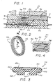
- Fig. 1 the preferred embodiment of the connector of the present invention, generally designated 10, comprising a plug 12 and a receptacle 14.
- the plug comprises a cylindrical shell 16 which is telescopically mounted over the front end of the cylindrical shell 18 of the receptacle.
- a plurality of socket contacts 20 are axially positioned in insulators 22 and 24 mounted in the shell 16. Each contact 20 receives a pin contact 26 which is mounted in an insulator 28 in the receptacle 14.
- a coupling nut 32 is retained on the shell 16 of the plug by retaining ring 34. The forward end of the coupling nut is threadadly engaged with the shell 18 of the receptacle.
- the EMI/RFI shield of the present invention is mounted in an annular groove 38 formed in the outer cylindrical surface 40 of the shell 16.
- the groove could be formed in the inner surface of the receptacle shell 18.
- the bottom 42 of the groove provides a cylindrical surface which faces the inner cylindrical surface 44 of the receptacle shell 18.
- the shield 36 is a composite, comprising a spring 46 and an elastomeric backup ring 48.
- the spring comprises a sheet metal band 50, formed of beryllium copper or the like, which is lanced to provide alternating slits 52 and 54 that extend to the opposite side edges 56 and 58 of the band.
- the slits define a plurality of spring fingers 59.
- the ring 48 which may be formed of a flurosilicone or the like, comprises a relatively wide outer portion 60 and a relatively narrow inner portion 62.
- the spring 46 is wrapped around the outer periphery 64 of the ring 48.
- the marginal portions 66 of the spring are bent or wrapped around the side portions 68 of the wide outer portion of the ring 48 to secure the spring to the ring.
- the marginal portions 66 of the spring will engage the sidewalls 70 of the groove 38 in the plug shell.
- the ends of the spring 46 are preferably secured together, in order to avoid separation of the ends of the spring on the elastomeric ring 48, by soldering, welding or the use of a metal clip (not shown).
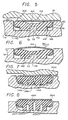
- the width of the shield 36 is slightly greater than the width of the groove 30 so that the shield will have an interference fit in the groove, causing the spring 46 to bow outwardly beyond the outer surface 40 of the plug shell, as best seen in Fig. 6
- annular flange 72 is formed in the groove 38 between the sidewalls 70.
- the flange extends tightly into an annular channel 74 formed in the inner surface of the elastomeric ring 48.
- Fig. 5 shows the condition of the shield 36 after the plug and receptacle have been mated.
- the shield is forced inwardly into the groove 38, and is radially compressed.
- This causes the narrow inner portion 62 of the ring 48, which extends below the marginal portions 66 of the spring 46, to be radially compressed which results in the sidewalls of the narrow portion 62 bulging outwardly slightly as seen in Fig. 5.
- the wide outer portion 66 of the ring is displaced laterally to press the marginal portions 66 of the spring against the sidewalls of the groove thereby increasing the normal force between the spring of the shield and the plug shell 16.
- the elastomeric ring 48 pushes the spring back up to its normal position illustrated in Fig. 6, thereby eliminating the "oil can" effect on the metal spring.
- the elastomeric ring also serves as a dampner during vibration, reducing fatigue stress on the spring. Further, by use of the elastomeric backup ring, heat treatment of the spring 46 is not required.
- a relatively short current path is provided between the connection of the spring 46 with the sidewalls 70 of the groove in plug shell 16, and the regions of the spring that engage the inner surface 44 of the receptacle shell 18, which reduces inductance, a contributor to poor EMI shielding effectiveness.
- the shield 36 of the present invention has the additional advantage that the spring 46 has low inductance between the adjacent spring fingers 59. Further, the spring is not subjected to excessive stresses, as may occur to reversely folded spring fingers of the prior art shield, because the major spring element in the composite shield 36 is the elastomeric ring 48. Preferably the elastomer of the ring has a durometer of about 40 while the thickness of the metal spring may be about .006 inch.
- an annular recess 76 is formed in the outer periphery 64 of the elastomeric ring 48, thereby providing a relatively thin section 78 of the elastomer between the two sides of the ring on the opposite sides of the flange 72.
- the two side portions 68 of the ring are capable of operating virtually independent of each other so that when a radially inwardly directed force is applied to the left side portion 68 of the ring by the receptacle shell 18, that force will not be imparted to the opposite side of the ring causing it to pop out of the groove.
- a shield in accordance to the present invention as described hereinabove can achieve a shielding effectiveness of about 100 to 108 dB, thereby greatly exceeding the shielding effectiveness of shields utilizing folded spring fingers, and further exceeding the shielding requirements of the aforementioned Government specification.
- Figs. 7 and 8 show an alternative form of the shield of the present invention, generally designated 36a.
- This shield is similar to the shield 36 except that the elastomeric ring 48a is formed with three annular channels 74a that open at the inside surface of the ring, forming relatively narrow elastomeric ribs 62a, which deform, as seen in Fig. 7, when the plug and receptacle shells are mated.
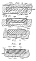
- FIG. 9 and 10 A further form of the invention is illustrated in Figs. 9 and 10 in which the elastomeric ring 48b is formed with relatively wide channels 74b and 76b in its lower and upper surfaces respectively.
- the spring 46b is formed so that its marginal portions 66b simply extend vertically down along the vertical sidewalls of the elastomeric ring, rather than being wrapped around the side portions of the ring to secure the spring thereto.
- an adhesive is provided between the outer periphery regions 64b of the elastomeric ring and the spring 46b to retain the parts assembled to each other. Further, an adhesive may be used to secure the inner surface of the ring to the bottom of the groove 38b.
- marginal portions 66c of the spring 46c extend down along the sidewalls of the elastomeric ring 48c similar to that described above in connection with Figs. 9 and 10. Again, an adhesive is used to secure the spring to the ring.
- the bottom of the groove 38c is formed with an upstanding annular section 72c which supports the central region of the ring 48c, but allows the side portions of the ring to be compressed downwardly into the groove upon mating with the receptacle shell.
- the elastomeric ring 48d is formed with two or more spaced annular recesses 76d in its outer periphery and two or more sets of annular recesses 74d in its inner periphery.
- the marginal portion 76d of one side of the spring is wrapped around the side portion 68d on the corresponding side of the ring to secure the spring to the ring.
- serpentine, watch spring type of spring 46 used with the shield of the present invention has the advantage that it may be secured to the backup ring 48, by bending over the marginal portions 66 of the spring, to provide a composite assembly prior to installation in the groove 38, since both the elastomeric ring and the spring may be expanded to fit the shield 36 over the plug shell for mounting in the groove.
- the marginal portions of the spring are not to be wrapped around the side portions of the elastomeric ring, but simply extend vertically downwardly, as in the embodiment illustrated in Figs. 9 and 10, the spring could take another form, such as a bowed metal band (not shown) formed with slots therearound, which are spaced at their opposite ends from the sides of the band.
- the elastomeric ring could be initially mounted in the groove in the plug shell, and then the band could be bit around the ring and the two free ends of the band secured by welding or the like.
- the shield of the present invention has been specifically described and illustrated herein as being in a circular form, it will be appreciated that the shield could assume other shapes depending upon the configuration of the connector.
- the shield could be mounted in a "rectangular" connector in which the element would assume the configuration of the rectangular shells of the connector.
- the term "ring” as used herein is intended to embrace loop structures of any configuration, including circular, rectangular, "D" shaped, etc.
- the shield of the present invention has been characterized herein as providing EMI/RFI shielding, it will be appreciated that the extent of shielding will be dependent upon the wave length of the interfering signals and the size of the gaps existing between the fingers of the spring. In some applications of the invention the shield may function simply as a ground connection, rather than an effective shield. Accordingly, it is intended that the present invention embrace devices which may function as either effective shields and ground connections, or only as grounding connections. Thus, the term "electrical connecting element" recited in the appended claims is intended to cover a device used for either or both functions.
Landscapes
- Details Of Connecting Devices For Male And Female Coupling (AREA)
Applications Claiming Priority (2)
| Application Number | Priority Date | Filing Date | Title |
|---|---|---|---|
| US07/104,714 US4808126A (en) | 1987-10-05 | 1987-10-05 | Electrical connector shield |
| US104714 | 1987-10-05 |
Publications (2)
| Publication Number | Publication Date |
|---|---|
| EP0310945A2 true EP0310945A2 (fr) | 1989-04-12 |
| EP0310945A3 EP0310945A3 (fr) | 1990-08-16 |
Family
ID=22301976
Family Applications (1)
| Application Number | Title | Priority Date | Filing Date |
|---|---|---|---|
| EP88116099A Withdrawn EP0310945A3 (fr) | 1987-10-05 | 1988-09-29 | Blindage pour connecteur électrique |
Country Status (2)
| Country | Link |
|---|---|
| US (1) | US4808126A (fr) |
| EP (1) | EP0310945A3 (fr) |
Cited By (7)
| Publication number | Priority date | Publication date | Assignee | Title |
|---|---|---|---|---|
| FR2653600A1 (fr) * | 1989-10-25 | 1991-04-26 | Commissariat Energie Atomique | Connecteur miniature pour cable plat blinde. |
| FR2684494A1 (fr) * | 1991-11-29 | 1993-06-04 | Souriau & Cie | Bracelet de blindage pour connecteurs electriques, et connecteurs equipes d'un tel bracelet. |
| WO2008008255A3 (fr) * | 2006-07-13 | 2008-08-28 | Raytheon Co | Joint étanche environnemental dynamique conducteur d'électricité |
| GB2464801A (en) * | 2008-10-01 | 2010-05-05 | Amphenol Corp | Grounding band for electrical connectors |
| US7906735B2 (en) | 2007-07-05 | 2011-03-15 | Raytheon Company | Electrically conductive dynamic environmental seal |
| WO2013156490A1 (fr) * | 2012-04-16 | 2013-10-24 | Tyco Electronics Amp Gmbh | Dispositif de contact résilient, arrangement de contact et connecteur de type fiche |
| WO2014048929A1 (fr) * | 2012-09-26 | 2014-04-03 | Tyco Electronics Amp Gmbh | Blindage électromagnétique, et connecteur électrique, électronique ou électro-optique |
Families Citing this family (5)
| Publication number | Priority date | Publication date | Assignee | Title |
|---|---|---|---|---|
| FR2636173B1 (fr) * | 1988-09-05 | 1992-04-24 | Radiall Sa | Boitier de connecteur blinde |
| US6743049B2 (en) * | 2002-06-24 | 2004-06-01 | Advanced Interconnections Corporation | High speed, high density interconnection device |
| AR051140A1 (es) * | 2004-10-20 | 2006-12-20 | Fisher Controls Int | Disposicion de filtro de entrada de avance - retardo para bucles de control electroneumaticos |
| US11936137B2 (en) * | 2018-12-28 | 2024-03-19 | Drägerwerk AG & Co. KGaA | Systems, monitor mounts, monitors, docks, racks, modules, belt mounts, couplings and connectors |
| US12478332B2 (en) | 2020-12-30 | 2025-11-25 | Drägerwerk AG & Co. KGaA | Mounting and locking mechanisms for a patient monitoring system |
Family Cites Families (17)
| Publication number | Priority date | Publication date | Assignee | Title |
|---|---|---|---|---|
| US3830957A (en) * | 1973-08-20 | 1974-08-20 | Amex Syst Inc | Grounding device for shielded electrical cable |
| SU571940A1 (ru) * | 1975-12-08 | 1977-09-05 | Предприятие П/Я А-3325 | Корпус радиоприбора |
| US4098633A (en) * | 1977-01-24 | 1978-07-04 | The United States Of America As Represented By The Secretary Of The Navy | Method of making radiation seal |
| US4243290A (en) * | 1978-10-30 | 1981-01-06 | Williams Robert A | Shield termination means for electrical connector |
| US4239318A (en) * | 1979-07-23 | 1980-12-16 | International Telephone And Telegraph Corporation | Electrical connector shield |
| US4330166A (en) * | 1979-08-16 | 1982-05-18 | Automation Industries, Inc. | Electrical connector substantially shielded against EMP and EMI energy |
| US4248492A (en) * | 1979-08-31 | 1981-02-03 | The Bendix Corporation | Electrical connector assembly having means for shielding against electromagnetic interference |
| US4349241A (en) * | 1980-05-09 | 1982-09-14 | Bunker Ramo Corporation | Electrical connector assembly having enhanced EMI shielding |
| US4326768A (en) * | 1980-06-02 | 1982-04-27 | The Bendix Corporation | Electrical connector grounding strap connection |
| JPS5836585U (ja) * | 1981-09-03 | 1983-03-09 | 第一電子工業株式会社 | 電気コネクタ |
| US4470657A (en) * | 1982-04-08 | 1984-09-11 | International Telephone & Telegraph Corporation | Circumferential grounding and shielding spring for an electrical connector |
| US4516815A (en) * | 1982-06-07 | 1985-05-14 | Spectrum Control, Inc. | RF filter connector |
| US4441780A (en) * | 1982-09-30 | 1984-04-10 | Automation Industries, Inc. | Plug and receptacle electrical connector |
| US4529257A (en) * | 1983-02-22 | 1985-07-16 | International-Telephone & Telegraph Corp. | Combined electrical shield and environmental seal for electrical connector |
| US4531790A (en) * | 1983-11-04 | 1985-07-30 | International Telephone & Telegraph Corporation | Electrical connector grounding ring |
| US4512623A (en) * | 1984-02-03 | 1985-04-23 | Allied Corporation | Electrical connector assembly having means for shielding electromagnetic interference |
| US4583809A (en) * | 1984-04-02 | 1986-04-22 | Allied Corporation | Electrical connector assembly having means for EMI shielding |
-
1987
- 1987-10-05 US US07/104,714 patent/US4808126A/en not_active Expired - Fee Related
-
1988
- 1988-09-29 EP EP88116099A patent/EP0310945A3/fr not_active Withdrawn
Cited By (15)
| Publication number | Priority date | Publication date | Assignee | Title |
|---|---|---|---|---|
| EP0426525A1 (fr) * | 1989-10-25 | 1991-05-08 | Commissariat A L'energie Atomique | Connecteur miniature pour câble plat blindé et organes de contact le constituant |
| FR2653600A1 (fr) * | 1989-10-25 | 1991-04-26 | Commissariat Energie Atomique | Connecteur miniature pour cable plat blinde. |
| FR2684494A1 (fr) * | 1991-11-29 | 1993-06-04 | Souriau & Cie | Bracelet de blindage pour connecteurs electriques, et connecteurs equipes d'un tel bracelet. |
| EP0545751A1 (fr) * | 1991-11-29 | 1993-06-09 | Framatome Connectors France | Bracelet de blindage pour connecteurs électriques, et connecteurs équipés d'un tel bracelet |
| US5445542A (en) * | 1991-11-29 | 1995-08-29 | Framatome Connectors France | Shielding band for electrical connectors and connector fitted with same |
| WO2008008255A3 (fr) * | 2006-07-13 | 2008-08-28 | Raytheon Co | Joint étanche environnemental dynamique conducteur d'électricité |
| US7906735B2 (en) | 2007-07-05 | 2011-03-15 | Raytheon Company | Electrically conductive dynamic environmental seal |
| GB2464801A (en) * | 2008-10-01 | 2010-05-05 | Amphenol Corp | Grounding band for electrical connectors |
| CN101714729A (zh) * | 2008-10-01 | 2010-05-26 | 安费诺有限公司 | 用于电连接装置的接地带 |
| US7753698B2 (en) | 2008-10-01 | 2010-07-13 | Amphenol Corporation | Grounding band for electrical connectors |
| FR2938381A1 (fr) * | 2008-10-01 | 2010-05-14 | Amphenol Corp | Bande de mise a la masse pour des connecteurs electriques. |
| GB2464801B (en) * | 2008-10-01 | 2012-12-26 | Amphenol Corp | Grounding band for electrical connectors |
| CN101714729B (zh) * | 2008-10-01 | 2014-03-19 | 安费诺有限公司 | 用于电连接装置的接地带 |
| WO2013156490A1 (fr) * | 2012-04-16 | 2013-10-24 | Tyco Electronics Amp Gmbh | Dispositif de contact résilient, arrangement de contact et connecteur de type fiche |
| WO2014048929A1 (fr) * | 2012-09-26 | 2014-04-03 | Tyco Electronics Amp Gmbh | Blindage électromagnétique, et connecteur électrique, électronique ou électro-optique |
Also Published As
| Publication number | Publication date |
|---|---|
| US4808126A (en) | 1989-02-28 |
| EP0310945A3 (fr) | 1990-08-16 |
Similar Documents
| Publication | Publication Date | Title |
|---|---|---|
| US4470657A (en) | Circumferential grounding and shielding spring for an electrical connector | |
| US4808128A (en) | Electrical connector assembly having means for EMI shielding | |
| US4529257A (en) | Combined electrical shield and environmental seal for electrical connector | |
| CN110011084B (zh) | 端子零件 | |
| CA1223313A (fr) | Bague de terre pour connecteur electrique | |
| US4033654A (en) | Electrical connector | |
| CN110011085B (zh) | 端子零件 | |
| US4428639A (en) | Electrical connector | |
| US3835443A (en) | Electrical connector shield | |
| US4808126A (en) | Electrical connector shield | |
| US4239318A (en) | Electrical connector shield | |
| US7635282B2 (en) | Coaxial cable shielding terminal with improved press-clamping portion | |
| US4741710A (en) | Electrical connector having a monolithic capacitor | |
| US8585415B2 (en) | Shielding braid termination for a shielded electrical connector | |
| US3840841A (en) | Electrical connector having rf filter | |
| GB2149232A (en) | Electrical connector with e.m.i. shield | |
| US5578790A (en) | Shielding gasket | |
| JP7212111B2 (ja) | 電気フェルール、電気接続デバイス、および電気コネクタ | |
| CN112740488B (zh) | 壳体一体型基板配合连接器及其制造方法 | |
| JPH11126655A (ja) | シールドコネクタ | |
| US11196202B2 (en) | Electrical connector and electronic device | |
| US3171887A (en) | Shielding and sealing gasket construction | |
| US3466590A (en) | Grounding device in an electrical connector | |
| US4509814A (en) | Electrical connector shell assembly with continuous annular seal | |
| KR100300448B1 (ko) | 금속외피를갖는전기커넥터 |
Legal Events
| Date | Code | Title | Description |
|---|---|---|---|
| PUAI | Public reference made under article 153(3) epc to a published international application that has entered the european phase |
Free format text: ORIGINAL CODE: 0009012 |
|
| AK | Designated contracting states |
Kind code of ref document: A2 Designated state(s): DE FR GB IT SE |
|
| PUAL | Search report despatched |
Free format text: ORIGINAL CODE: 0009013 |
|
| AK | Designated contracting states |
Kind code of ref document: A3 Designated state(s): DE FR GB IT SE |
|
| 17P | Request for examination filed |
Effective date: 19900906 |
|
| 17Q | First examination report despatched |
Effective date: 19920410 |
|
| STAA | Information on the status of an ep patent application or granted ep patent |
Free format text: STATUS: THE APPLICATION IS DEEMED TO BE WITHDRAWN |
|
| 18D | Application deemed to be withdrawn |
Effective date: 19920821 |