EP0310988A2 - Dispositif pour changer de direction un courant de produits, notamment de produits en papier alimentés en formation chevauchante - Google Patents
Dispositif pour changer de direction un courant de produits, notamment de produits en papier alimentés en formation chevauchante Download PDFInfo
- Publication number
- EP0310988A2 EP0310988A2 EP88116312A EP88116312A EP0310988A2 EP 0310988 A2 EP0310988 A2 EP 0310988A2 EP 88116312 A EP88116312 A EP 88116312A EP 88116312 A EP88116312 A EP 88116312A EP 0310988 A2 EP0310988 A2 EP 0310988A2
- Authority
- EP
- European Patent Office
- Prior art keywords
- deflection device
- deflection
- carrier
- guide roller
- axis
- Prior art date
- Legal status (The legal status is an assumption and is not a legal conclusion. Google has not performed a legal analysis and makes no representation as to the accuracy of the status listed.)
- Granted
Links
- 230000015572 biosynthetic process Effects 0.000 title description 4
- 230000001154 acute effect Effects 0.000 claims description 3
- 230000006978 adaptation Effects 0.000 description 1
- 238000010276 construction Methods 0.000 description 1
- 238000001514 detection method Methods 0.000 description 1
- 230000000694 effects Effects 0.000 description 1
- 239000004033 plastic Substances 0.000 description 1
Images
Classifications
-
- B—PERFORMING OPERATIONS; TRANSPORTING
- B65—CONVEYING; PACKING; STORING; HANDLING THIN OR FILAMENTARY MATERIAL
- B65H—HANDLING THIN OR FILAMENTARY MATERIAL, e.g. SHEETS, WEBS, CABLES
- B65H5/00—Feeding articles separated from piles; Feeding articles to machines
- B65H5/02—Feeding articles separated from piles; Feeding articles to machines by belts or chains, e.g. between belts or chains
- B65H5/021—Feeding articles separated from piles; Feeding articles to machines by belts or chains, e.g. between belts or chains by belts
- B65H5/023—Feeding articles separated from piles; Feeding articles to machines by belts or chains, e.g. between belts or chains by belts between a pair of belts forming a transport nip
-
- B—PERFORMING OPERATIONS; TRANSPORTING
- B65—CONVEYING; PACKING; STORING; HANDLING THIN OR FILAMENTARY MATERIAL
- B65H—HANDLING THIN OR FILAMENTARY MATERIAL, e.g. SHEETS, WEBS, CABLES
- B65H29/00—Delivering or advancing articles from machines; Advancing articles to or into piles
- B65H29/66—Advancing articles in overlapping streams
-
- B—PERFORMING OPERATIONS; TRANSPORTING
- B65—CONVEYING; PACKING; STORING; HANDLING THIN OR FILAMENTARY MATERIAL
- B65H—HANDLING THIN OR FILAMENTARY MATERIAL, e.g. SHEETS, WEBS, CABLES
- B65H2301/00—Handling processes for sheets or webs
- B65H2301/30—Orientation, displacement, position of the handled material
- B65H2301/34—Modifying, selecting, changing direction of displacement
- B65H2301/341—Modifying, selecting, changing direction of displacement without change of plane of displacement
-
- B—PERFORMING OPERATIONS; TRANSPORTING
- B65—CONVEYING; PACKING; STORING; HANDLING THIN OR FILAMENTARY MATERIAL
- B65H—HANDLING THIN OR FILAMENTARY MATERIAL, e.g. SHEETS, WEBS, CABLES
- B65H2404/00—Parts for transporting or guiding the handled material
- B65H2404/20—Belts
- B65H2404/22—Cross section profile
- B65H2404/221—Round belt
-
- B—PERFORMING OPERATIONS; TRANSPORTING
- B65—CONVEYING; PACKING; STORING; HANDLING THIN OR FILAMENTARY MATERIAL
- B65H—HANDLING THIN OR FILAMENTARY MATERIAL, e.g. SHEETS, WEBS, CABLES
- B65H2404/00—Parts for transporting or guiding the handled material
- B65H2404/20—Belts
- B65H2404/26—Particular arrangement of belt, or belts
- B65H2404/261—Arrangement of belts, or belt(s) / roller(s) facing each other for forming a transport nip
Definitions
- the invention relates to a deflection device for a flow of products, in particular in the form of scales, of paper products with an inlet, a ramp plate and an outlet.
- deflection stations which usually have a horizontal plate, a run-up plate running perpendicular to it and adjustable on the horizontal plates, and are optionally provided with a deflection roller. The products are thus deflected by 90 ° on the table or the platen.
- the invention is based, to steer the product flow at the inlet in different angular positions - depending on the requirements.
- Press belts in the sense of the invention also include belts, appropriately strong rubber bands or profiled rubber bands; it also includes link chains, possibly with a rubber pad facing the product stream.
- the inlet can or the like at least two interacting pairs of press belts. have, whose conveying direction is adjustable between 0 - 45 °.
- each pair of press belts or the like a guide roller, a guide roller or the like. on, the axis of which runs perpendicular to the direction of entry - preferably in a horizontal plane - and which has at least one guide roller with an axis which can be pivoted thereon, preferably in the horizontal plane.
- the pivotable axis or the like on a support. be provided which has at least one deflection roller or the like. has an axis perpendicular to the axes of the guide roller wheels, the press belt or the like. can have a round or approximately round cross-section.
- the pulleys or the like. are expediently arranged in pairs.
- the holder and the carrier of the one endless press belt or the like close. or the like with respect to the holder and the carrier of the associated press belt. an acute angle opening towards the feed conveyor.
- at least one pair of press belts or the like is or are. adjustable in height with respect to the adjacent pair of press belts. By adjusting the height of a pair of press belts or the like not lying on the edge of the product stream. can be achieved that the formation receives a small bow in the middle, whereby the paper product or the entire formation is stiffened when entering the deflection device. Of course, it doesn't matter whether this little bug is pointing downwards or upwards.
- the holder of the lower press belts or the like. and those of the upper press belts or the like. are expediently each mounted on a shaft and each carry an optionally driven guide roller, guide roller or the like; both shafts or the like can be attached by gears attached to one end. run synchronously, whereby only one shaft can be driven at the other end.
- the carrier or the like taper to a point in the horizontal plane and a guide roller or the like. wear.
- the construction is simplified insofar as the detection of the product flow takes place only at a distance from the front guide rollers, specifically after the intended deflection of the press belts into the intended angular position.
- the carrier or the like. can at the edge of the inlet side at least at a distance from its lower and the upper perpendicular to the axis of the guide roller, guide roller or the like. running surface at least one deflection roller, deflection roller or the like. wear.
- An embodiment is particularly preferred in which the holder and / or carrier or the like, preferably the upper holder of each pair of press belts, is pivotably and resiliently mounted about its shaft. In this way, on the one hand a resilient support of the upper holder and carrier is achieved and on the other hand an adaptation to different strengths of the product flow is possible.
- the holder of the respective press belts or the like. are preferably slidable on their shafts and the like on a shaft parallel to the shaft. lockable.
- the deflection rollers, deflection rollers or the like provided above and below the carrier. each preferably have a common approximately perpendicular shaft or the like. on. It is also possible that the two waves or the like. in a vertical, possibly square frame or the like. are held, which is releasably attachable to the inlet side of the deflection device.
- the carrier or the like are for a gradual adjustment. Wedges or the like of various sizes.
- An axis of the deflection roller or the like can also.
- a carrier or the like be designed as a pivot axis of the latter.
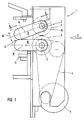
- the two shafts 2 and 3 are driven synchronously via gear wheels 6 and 7 provided at one of their ends.
- Pairs of elements 8 are mounted on each shaft 2 and 3. At least two such pairs of elements must be provided; In conventional rotary cutting systems with a corner deflection having the frame 1 at the inlet, at least three, possibly four to five pairs of elements 8 will be provided.
- the direction of product flow from the feed conveyor is indicated by arrow 9.
- Each pair of elements consists of two essentially identical elements, the lower element 10 being locked to a rail 11 which runs perpendicular to the plane of the drawing and extends across the width of the frame.
- the longitudinal axis 12 of the lower element 10 runs horizontally. The fastening of the individual lower elements on the rail 11 takes place at regular intervals.
- the upper element 13 is with its longitudinal axis 14 at an acute angle to the longitudinal axis 12 of the lower Elements arranged; it is - as described in more detail below - spring-loaded and adjustable in height.
- the individual elements 13 can also be pivoted about the pivot point 15 in the direction of the arrow 16.
- the lower elements 10 are locked via pins 20 that can be screwed into the rod 11.
- Each element 10 or 13 has a block-like holder 21 and a carrier 22.
- the block-like holder surrounds a guide roller 23 in the form of a fork, the axis 24 of which runs perpendicular to the product flow.
- the guide roller 23 is provided with two semicircular ring grooves for receiving a press belt 25 with a round cross section.
- the press belt 25 is an endless belt, which is held at the outlet by a guide roller 26, the axis 27 of which runs perpendicular to the product flow, but can be pivoted in the horizontal plane between 0 ° and 45 °.
- the carrier 22 with the guide roller 26 is adjusted at an angle of 45 ° to the direction of flow of the product stream.
- the endless belt 25 running above and below the holder 21 and the carrier 22 is guided through two deflection rollers 27 and 28 on the top of the carrier 22 and through a corresponding pair of deflection rollers on the underside of the carrier 22.
- the endless belt 25 runs on the top of the holder 21 and the carrier 22 as shown and on the Bottom accordingly.
- deflecting rollers 27 and 28 and the corresponding, provided on the underside of the support 22 deflecting rollers 29 and 30 are formed so that the respective annular groove 23 'is offset in relation to the center plane of the respective deflecting rollers to the outside. In this way it is achieved that the outside of the endless belt 25 projects beyond the free edge of the respective deflection roller 27-30.
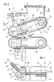
- the two arms 40, 41 of the carrier 22 engage around a corresponding projection 42 of the holder 22. While the shaft 30, not shown, is mounted in this projection 42, the corresponding projection (see FIG .3) a recess 43 into which the continuous shaft of the axis 44 is accommodated when the carrier 22 is pivoted in.
- the upper element 13 can be pivoted upward about the axis 50, a pin 51 on the upper side of the carrier 22 engaging in a longitudinal slot 52 running parallel to the plane of the drawing.
- the longitudinal slot ensures that the carrier 22 of the element 13 cannot escape laterally.
- the flange 53 having the longitudinal slot 52 can be pivoted about the axis 54, so that the position of the carrier 22 of the element 13 shown from above in FIG. 3 can be achieved.
- the longitudinal slot 52 also allows the element 13 to be pivoted up about the axis 5, the pin 51 projecting into the longitudinal slot being able to be moved back and forth between the two positions shown.
- the holder 21 of the upper element 13 is also connected via a flange 60 to a spring 61, so that the element 13 can also spring to a certain extent about the axis 50.
- the support 22 can be locked in any angular position between 0 ° and 45 ° in any way; however, it is also possible to effect a gradual locking of this carrier in the angular position between 0 ° and 45 ° by means of wedges.
- the deflection of the product stream from the arrow direction 9, for example in the arrow direction 62, is carried out in such a way that the product stream is pushed by the feed conveyor into the open gap between the two guide rollers 23 with its endless belts 25 and that the product stream is narrowed by the narrowing gap, as in FIG Fig. 2 shown, only detected in the region of the guide rollers 26 and deflected accordingly.
- belts or belts e.g. used in an upright position; it is also possible to use 25 link chains instead of the endless belts; these would then have to be provided on the outside with appropriate rubber profiles or elastic plastic profiles.
Landscapes
- Engineering & Computer Science (AREA)
- Mechanical Engineering (AREA)
- Structure Of Belt Conveyors (AREA)
- Separation, Sorting, Adjustment, Or Bending Of Sheets To Be Conveyed (AREA)
- Delivering By Means Of Belts And Rollers (AREA)
- Sorting Of Articles (AREA)
- Registering Or Overturning Sheets (AREA)
- Advancing Webs (AREA)
Priority Applications (1)
| Application Number | Priority Date | Filing Date | Title |
|---|---|---|---|
| AT88116312T ATE79828T1 (de) | 1987-10-07 | 1988-10-03 | Umlenkvorrichtung fuer einen produktstrom, insbesondere von in schuppenform herangefuehrten papierprodukten. |
Applications Claiming Priority (2)
| Application Number | Priority Date | Filing Date | Title |
|---|---|---|---|
| DE3733906 | 1987-10-07 | ||
| DE3733906A DE3733906C2 (de) | 1987-10-07 | 1987-10-07 | Umlenkvorrichtung für einen Produktstrom |
Publications (3)
| Publication Number | Publication Date |
|---|---|
| EP0310988A2 true EP0310988A2 (fr) | 1989-04-12 |
| EP0310988A3 EP0310988A3 (en) | 1989-06-07 |
| EP0310988B1 EP0310988B1 (fr) | 1992-08-26 |
Family
ID=6337814
Family Applications (1)
| Application Number | Title | Priority Date | Filing Date |
|---|---|---|---|
| EP88116312A Expired - Lifetime EP0310988B1 (fr) | 1987-10-07 | 1988-10-03 | Dispositif pour changer de direction un courant de produits, notamment de produits en papier alimentés en formation chevauchante |
Country Status (6)
| Country | Link |
|---|---|
| US (1) | US4900007A (fr) |
| EP (1) | EP0310988B1 (fr) |
| JP (1) | JP2851283B2 (fr) |
| AT (1) | ATE79828T1 (fr) |
| DE (1) | DE3733906C2 (fr) |
| DK (1) | DK168281B1 (fr) |
Cited By (2)
| Publication number | Priority date | Publication date | Assignee | Title |
|---|---|---|---|---|
| US6406014B1 (en) | 1999-05-31 | 2002-06-18 | Ferag Ag | Method and apparatus for transporting objects arriving in an overlapping formation |
| DE102009035859A1 (de) * | 2009-07-31 | 2011-08-18 | Hohner Maschinenbau GmbH, 78532 | Fördermittel für Druckereiprodukt |
Families Citing this family (5)
| Publication number | Priority date | Publication date | Assignee | Title |
|---|---|---|---|---|
| GB2251427A (en) * | 1990-11-15 | 1992-07-08 | Unisys Corp | Document transport track drive mechanism |
| US5590873A (en) * | 1995-10-18 | 1997-01-07 | Bell & Howell Phillipsburg Company | Document set accumulator having shaft-mounted multi-grooved pulleys for tool-less adjustment of lateral belt positioning |
| US6705818B2 (en) * | 2000-03-17 | 2004-03-16 | Fuji Photo Film Co., Ltd. | Package take-out apparatus, package container thereof and unwrapping apparatus |
| DE10063068C1 (de) * | 2000-12-18 | 2002-04-18 | Markus Gampl | Umlenkvorrichtung für einen Strom von in Formation auftretenden Flächengebilden, insbesondere Papierprodukten |
| DE102006045268A1 (de) * | 2006-09-22 | 2008-04-10 | Eastman Kodak Company | Vorrichtung zum Drehen eines flächigen Gutes, vorzugsweise von Bögen |
Family Cites Families (17)
| Publication number | Priority date | Publication date | Assignee | Title |
|---|---|---|---|---|
| US2216546A (en) * | 1939-03-31 | 1940-10-01 | Goodman Mfg Co | Articulated conveyer |
| US2593242A (en) * | 1947-02-21 | 1952-04-15 | Cutler Hammer Inc | Switching type conveyer |
| US2725972A (en) * | 1954-05-07 | 1955-12-06 | Cutler Hammer Inc | Mechanism for conveying and counting flat, flexible articles delivered in a stream |
| CH435323A (de) * | 1965-05-03 | 1967-05-15 | Plamag Plauener Druckmaschinen | Vorrichtung zum Auslegen von Druckerzeugnissen |
| US3595565A (en) * | 1969-08-21 | 1971-07-27 | Burroughs Corp | Sheet item transport and aligning mechanism |
| JPS5213736Y2 (fr) * | 1971-07-08 | 1977-03-28 | ||
| DE2224981C3 (de) * | 1972-05-23 | 1979-09-06 | Maschinenbau Oppenweiler Binder & Co, 7155 Oppenweiler | Schuppenauslage für Papierverarbeitungsmaschinen, insbesondere Falzmaschine |
| JPS50150086U (fr) * | 1974-05-28 | 1975-12-13 | ||
| DE2529103C3 (de) * | 1975-06-30 | 1979-07-19 | Siemens Ag, 1000 Berlin Und 8000 Muenchen | Transportvorrichtung für blattförmiges Material |
| AT340821B (de) * | 1975-08-20 | 1978-01-10 | Schmidt Alexander Gmbh | Fordervorrichtung |
| US4062532A (en) * | 1976-04-23 | 1977-12-13 | Koppers Company, Inc. | Apparatus for feeding and transporting paperboard blanks |
| DD126257B1 (de) * | 1976-06-22 | 1981-01-28 | Guenter Thieme | Bandfoerdervorrichtung zum ausgeben und weiterfoerdern von bogen |
| DE2823247C2 (de) * | 1978-05-27 | 1983-07-28 | Albert-Frankenthal Ag, 6710 Frankenthal | Einrichtung zur Umlenkung eines aus bogenförmigen Produkten bestehenden Produktstroms |
| AU5767080A (en) * | 1979-04-24 | 1980-10-30 | Itt Industries, Inc. | Article sorter |
| US4424966A (en) * | 1981-09-03 | 1984-01-10 | Harris Graphics Corporation | Mechanism for conveying articles selectively into different paths |
| JPS6020295A (ja) * | 1983-07-15 | 1985-02-01 | 株式会社日立製作所 | 紙葉類回収搬送路 |
| JPS61131A (ja) * | 1984-05-29 | 1986-01-06 | オムロン株式会社 | ラベル貼設装置 |
-
1987
- 1987-10-07 DE DE3733906A patent/DE3733906C2/de not_active Expired - Lifetime
-
1988
- 1988-10-03 US US07/252,853 patent/US4900007A/en not_active Expired - Lifetime
- 1988-10-03 AT AT88116312T patent/ATE79828T1/de not_active IP Right Cessation
- 1988-10-03 EP EP88116312A patent/EP0310988B1/fr not_active Expired - Lifetime
- 1988-10-05 JP JP63252878A patent/JP2851283B2/ja not_active Expired - Lifetime
- 1988-10-06 DK DK559788A patent/DK168281B1/da active
Cited By (2)
| Publication number | Priority date | Publication date | Assignee | Title |
|---|---|---|---|---|
| US6406014B1 (en) | 1999-05-31 | 2002-06-18 | Ferag Ag | Method and apparatus for transporting objects arriving in an overlapping formation |
| DE102009035859A1 (de) * | 2009-07-31 | 2011-08-18 | Hohner Maschinenbau GmbH, 78532 | Fördermittel für Druckereiprodukt |
Also Published As
| Publication number | Publication date |
|---|---|
| JPH0289763A (ja) | 1990-03-29 |
| EP0310988A3 (en) | 1989-06-07 |
| DK168281B1 (da) | 1994-03-07 |
| EP0310988B1 (fr) | 1992-08-26 |
| US4900007A (en) | 1990-02-13 |
| ATE79828T1 (de) | 1992-09-15 |
| DE3733906A1 (de) | 1989-04-20 |
| JP2851283B2 (ja) | 1999-01-27 |
| DK559788A (da) | 1989-04-08 |
| DE3733906C2 (de) | 2000-12-14 |
| DK559788D0 (da) | 1988-10-06 |
Similar Documents
| Publication | Publication Date | Title |
|---|---|---|
| EP0242865B1 (fr) | Dispositif pour changer la direction de transport d'imprimés ou similaires | |
| DE7311210U (de) | Vorrichtung fuer den vertikalen transport von koerpern | |
| DE2702798A1 (de) | Glasplattenkanten-schleifmaschine | |
| DE3244422C2 (fr) | ||
| DE3835124A1 (de) | Falzmaschine, insbesondere stauchfalzmaschine | |
| EP0310988A2 (fr) | Dispositif pour changer de direction un courant de produits, notamment de produits en papier alimentés en formation chevauchante | |
| DE4142824A1 (de) | Vorrichtung zum drehen von flachliegend voranbewegten werkstuecken | |
| DE1574639C3 (de) | Vorrichtung zum Ausrichten eines in einer Richtung bewegbaren Bandes oder Bandabschnittes aus klebrigem Reifenbaumaterial in bezug auf eine zur Förderrichtung parallele lotrechte Bezugsebene | |
| DE2415003A1 (de) | Fotoelektrische zaehlvorrichtung fuer papierfoerderer | |
| DE69915699T2 (de) | Vorrichtung zum transport von flachen gegenständen zwischen verarbeitungseinrichtungen | |
| AT390595B (de) | Kettenfoerderer | |
| EP1153714B1 (fr) | Dispositif pour déplacer en avancement des produits de boulangerie | |
| EP0234333B1 (fr) | Convoyeur pour troncs d'arbres | |
| DE2744957C3 (de) | Zubringvorrichtung für Massenteile | |
| AT394965B (de) | Vorrichtung zum kontinuierlichen trennen von uebereinanderliegenden blattfoermigen gebilden | |
| DE3616801C1 (de) | Gurtbecherwerk fuer Senkrechtfoerderer | |
| DE2025667B2 (de) | Endloser Kettenförderer | |
| DE4202735A1 (de) | Vorrichtung zum richten von flaechigen stanzteilen aus metall | |
| DE886213C (de) | Tischfraesmaschine zur Holzbearbeitung | |
| DE2531486C3 (de) | Maschine zum Zählen von flachen Körpern, insbesondere Bücher, Hefte, Papierblätter o.dgl | |
| DE718928C (de) | Einrichtung zum Abgraten von Flachziegeln | |
| DE2112908A1 (de) | Verfahren und Vorrichtung zum Zerteilen einer Glasplatte in rechteckige Stuecke vorgegebener Groesse | |
| DE2431753A1 (de) | Vorrichtung fuer baeckereien zum aufsetzen oder abheben von deckeln auf bzw. von in blechdosen befindlichen backwaren, insbesondere kastenbrot | |
| DE1966094A1 (de) | Niederhalter fuer Schneideinrichtungen | |
| DE2211267A1 (de) | Saughebevorrichtung |
Legal Events
| Date | Code | Title | Description |
|---|---|---|---|
| PUAI | Public reference made under article 153(3) epc to a published international application that has entered the european phase |
Free format text: ORIGINAL CODE: 0009012 |
|
| AK | Designated contracting states |
Kind code of ref document: A2 Designated state(s): AT BE CH ES FR GB GR IT LI LU NL SE |
|
| PUAL | Search report despatched |
Free format text: ORIGINAL CODE: 0009013 |
|
| AK | Designated contracting states |
Kind code of ref document: A3 Designated state(s): AT BE CH ES FR GB GR IT LI LU NL SE |
|
| 17P | Request for examination filed |
Effective date: 19891103 |
|
| 17Q | First examination report despatched |
Effective date: 19910424 |
|
| GRAA | (expected) grant |
Free format text: ORIGINAL CODE: 0009210 |
|
| AK | Designated contracting states |
Kind code of ref document: B1 Designated state(s): AT BE CH ES FR GB GR IT LI LU NL SE |
|
| PG25 | Lapsed in a contracting state [announced via postgrant information from national office to epo] |
Ref country code: NL Effective date: 19920826 Ref country code: BE Effective date: 19920826 Ref country code: GR Free format text: LAPSE BECAUSE OF FAILURE TO SUBMIT A TRANSLATION OF THE DESCRIPTION OR TO PAY THE FEE WITHIN THE PRESCRIBED TIME-LIMIT Effective date: 19920826 Ref country code: ES Free format text: THE PATENT HAS BEEN ANNULLED BY A DECISION OF A NATIONAL AUTHORITY Effective date: 19920826 Ref country code: SE Free format text: THE PATENT HAS BEEN ANNULLED BY A DECISION OF A NATIONAL AUTHORITY Effective date: 19920826 |
|
| REF | Corresponds to: |
Ref document number: 79828 Country of ref document: AT Date of ref document: 19920915 Kind code of ref document: T |
|
| PG25 | Lapsed in a contracting state [announced via postgrant information from national office to epo] |
Ref country code: LU Free format text: LAPSE BECAUSE OF NON-PAYMENT OF DUE FEES Effective date: 19921031 |
|
| ITF | It: translation for a ep patent filed | ||
| ET | Fr: translation filed | ||
| GBT | Gb: translation of ep patent filed (gb section 77(6)(a)/1977) | ||
| NLV1 | Nl: lapsed or annulled due to failure to fulfill the requirements of art. 29p and 29m of the patents act | ||
| PLBE | No opposition filed within time limit |
Free format text: ORIGINAL CODE: 0009261 |
|
| STAA | Information on the status of an ep patent application or granted ep patent |
Free format text: STATUS: NO OPPOSITION FILED WITHIN TIME LIMIT |
|
| 26N | No opposition filed | ||
| REG | Reference to a national code |
Ref country code: GB Ref legal event code: IF02 |
|
| PGFP | Annual fee paid to national office [announced via postgrant information from national office to epo] |
Ref country code: CH Payment date: 20071015 Year of fee payment: 20 Ref country code: IT Payment date: 20071025 Year of fee payment: 20 Ref country code: AT Payment date: 20071015 Year of fee payment: 20 |
|
| PGFP | Annual fee paid to national office [announced via postgrant information from national office to epo] |
Ref country code: GB Payment date: 20071023 Year of fee payment: 20 Ref country code: FR Payment date: 20071016 Year of fee payment: 20 |
|
| REG | Reference to a national code |
Ref country code: CH Ref legal event code: PL |
|
| REG | Reference to a national code |
Ref country code: GB Ref legal event code: PE20 Expiry date: 20081002 |
|
| PG25 | Lapsed in a contracting state [announced via postgrant information from national office to epo] |
Ref country code: GB Free format text: LAPSE BECAUSE OF EXPIRATION OF PROTECTION Effective date: 20081002 |