EP0311027A2 - Vanne régulatrice de pression commandée par une force avec clapet subdivisé - Google Patents
Vanne régulatrice de pression commandée par une force avec clapet subdivisé Download PDFInfo
- Publication number
- EP0311027A2 EP0311027A2 EP88116432A EP88116432A EP0311027A2 EP 0311027 A2 EP0311027 A2 EP 0311027A2 EP 88116432 A EP88116432 A EP 88116432A EP 88116432 A EP88116432 A EP 88116432A EP 0311027 A2 EP0311027 A2 EP 0311027A2
- Authority
- EP
- European Patent Office
- Prior art keywords
- valve member
- pressure medium
- force
- sealing ring
- opening
- Prior art date
- Legal status (The legal status is an assumption and is not a legal conclusion. Google has not performed a legal analysis and makes no representation as to the accuracy of the status listed.)
- Withdrawn
Links
Images

Classifications
-
- B—PERFORMING OPERATIONS; TRANSPORTING
- B60—VEHICLES IN GENERAL
- B60T—VEHICLE BRAKE CONTROL SYSTEMS OR PARTS THEREOF; BRAKE CONTROL SYSTEMS OR PARTS THEREOF, IN GENERAL; ARRANGEMENT OF BRAKING ELEMENTS ON VEHICLES IN GENERAL; PORTABLE DEVICES FOR PREVENTING UNWANTED MOVEMENT OF VEHICLES; VEHICLE MODIFICATIONS TO FACILITATE COOLING OF BRAKES
- B60T15/00—Construction arrangement, or operation of valves incorporated in power brake systems and not covered by groups B60T11/00 or B60T13/00
- B60T15/02—Application and release valves
-
- G—PHYSICS
- G05—CONTROLLING; REGULATING
- G05D—SYSTEMS FOR CONTROLLING OR REGULATING NON-ELECTRIC VARIABLES
- G05D16/00—Control of fluid pressure
- G05D16/04—Control of fluid pressure without auxiliary power
- G05D16/10—Control of fluid pressure without auxiliary power the sensing element being a piston or plunger
- G05D16/109—Control of fluid pressure without auxiliary power the sensing element being a piston or plunger with two or more pistons acting as a single pressure controller that move together over range of motion during normal operations
Definitions
- the present invention relates to a force-controlled pressure control valve, consisting of a housing with at least one pressure medium inlet opening, a pressure medium outlet opening and a relief opening, and with a housing chamber which is permanently connected to the pressure medium inlet opening and can be shut off against the pressure medium outlet opening and in which a valve member designed as a hollow cylinder is axially adjustable and guided with little radial play is, one edge of which surrounds an opening connected to the pressure medium outlet opening and the other edge of which cooperates with a valve seat arranged coaxially with the relief opening and surrounds a second valve seat in a cover of the valve member, with which an actuator which applies the adjusting force to the valve member is arranged within the relief opening cooperates with an annular edge and this actuating force is one of an elastic one that shuts off the housing chamber against the pressure medium outlet opening, counteracts generated restoring force generated sealing ring.
- Such a pressure control valve is known from DE-OS 33 40 525.
- the elastic sealing ring is arranged on a collar of the housing chamber in such a way that it lies sealingly against the inner wall of the housing chamber on the one hand and on the other hand against the circumference of the valve member in the region a ring shoulder of the same.
- this arrangement can result in the sealing ring being pressed out of its position into the annular gap between the valve member above the annular shoulder and the wall of the housing chamber.
- the sealing ring can jam, so that the functionality of the valve is impaired.
- the sealing ring may also be damaged.
- the invention has for its object to improve the pressure control valve of the type described in such a way that the sealing ring can not be pressed out of its position by the pressure loads occurring in the valve, so that the above disadvantages cannot occur.
- this is achieved in that the hollow cylinder forming the valve member is subdivided in such a way that a pressure-balanced mounting of the sealing ring with respect to the pressure present in the hollow cylinder is given by pressurizing the sealing ring from both sides of the interior of the valve member.
- the sealing ring is pressed from both sides, i.e. H.
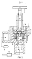
- the force-controlled pressure control valve is arranged between a pressure medium source 9 for any, but in particular pneumatic, fluid, for example a compressed air tank, and a consumer 19, for example the actuating cylinder of the compressed air brake of a vehicle.
- a valve housing 1 of the pressure control valve has a pressure medium inlet 8, a first pressure medium outlet 18 to the consumer 19 and a second pressure medium outlet 18 a to the ambient medium, for example to the ambient air.
- the consumer 19 In the operating position of the valve shown in FIG. 1, the consumer 19 is connected to the pressure medium outlet 18a. In another operating position of the valve, referred to as the ventilation position, the consumer 19 is connected to the pressure medium source 9, see FIG. 2.
- the maximum pressure that can be generated in the consumer 19 by supplying pressure medium from the pressure medium source 9 is the pressure actually prevailing in the pressure medium source 9. Which pressure actually sets in the consumer 19 as the partial pressure of the pressure prevailing in the pressure medium source 9 depends on a force which is forcibly brought into effect as a control signal on a control piston 3 in the direction of the longitudinal axis thereof, for example by means of an electromagnet or a mechanical actuation .
- the longitudinal axes of pressure medium inlet 8 and pressure medium outlet 18 intersect preferably at an angle of 90 °.
- Pressure medium inlet 8 and pressure medium outlet 18 open into a storage chamber 7, which is arranged in the housing 1 coaxially with the pressure medium outlet 18 and is enclosed by a wall 24 and is part of a bore that steps the housing 1 inwards from one end to the other, penetrates.
- the storage chamber 7 is closed at the end opposite the pressure medium outlet 18 by a control membrane 4 made of an elastomer, the outside of which rests on a cover 5, which presses the control membrane 4 with its outer edge without play into an annular groove 23 of the valve housing 1.
- the cover 5 is fixed in the housing 1 by suitable means in such a position that the control membrane 4 is held in the groove 23 without play.
- a bore 30 is arranged in the cover 5 with the same axis as the storage chamber 7.
- a bore 22 is also arranged coaxially with the storage chamber 7.
- the pressure medium outlet 18 opens into a control chamber 7a, which is arranged in the housing 1 and is enclosed by a wall 37.
- a valve member 2 is arranged in the storage chamber 7, which is essentially cylindrical and is formed from two coaxial cylinder sleeves 50, 51, of which the lower cylinder sleeve 51 is partially guided circumferentially with little play in the upper cylinder sleeve 50, and the elastic sealing ring 10 is arranged at the outer end of the circumferential gap 52 existing between the two cylinder sleeves 50, 51.
- the upper cylinder sleeve 50 which has the sealing edge 31, comprises the lower cylinder sleeve 51.
- a peripheral groove 53 is formed directly at the outer end of the peripheral gap 52, in which the sealing ring 10 is partially accommodated.
- the sealing ring 10 is loosely mounted in the circumferential groove and the The depth of the circumferential groove is preferably about one third of the diameter of the ring cross section.
- the sealing ring 10 is mounted with its area lying outside the circumferential groove 53 between the adjacent end 54, the upper cylinder sleeve 50 and a collar 1b formed in the housing chamber and by a reduction in diameter of the housing chamber.
- the lower cylinder sleeve 51 with its area adjoining the sealing ring and facing the outlet 18, is guided into the chamber area adjoining the collar 1b and ends at a distance above a bottom 55 of the housing chamber.
- the embodiment and arrangement of the cylinder sleeves 50, 51 and the sealing ring 10 described above achieve that the sealing ring from above and below, on the one hand, via the circumferential gap 52 and, on the other hand, via the circumferential gap 56 between the lower cylinder sleeve 51 and the inner wall of the chamber 7 with the pressure prevailing within the interior 35, so that the pressure loads occurring from the interior 35 cancel each other out because they act on the sealing ring 10 in the opposite manner.
- the sealing ring lies with a precisely defined diameter within the housing chamber 7.
- lugs 39 are formed, distributed uniformly over the circumference, with which the valve member does not have radial play , but is guided axially adjustable in the cylindrical storage chamber 7.
- the cover 40 has a number of axial bores 34 distributed centrally around its outer edge, and a further axial bore 34a in the center.
- valve member 50 In the operating position of the valve according to the invention shown in FIG. 1, the valve member 50 rests with its upper edge 31 as a sealing edge on the underside of the control membrane 4 and its lower end 54 against the sealing ring 10. The storage space 7 is thus blocked off from the control chamber 7a.
- the pressure medium outlet 18 communicates with the interior 35 of the valve member 2, which communicates with the environment via the axial bores 34, the central bore 34a, the bore 22 of the control membrane 4 and the gap between the control piston 3 and the bore 30 and the pressure medium outlet 18a of the valve is connected.
- the operating position of the valve shown in FIG. 1 is thus identified as the operating position in which the consumer 19 is vented. Fluid enclosed in the consumer 19 can escape from the consumer 19 via the valve. The pressure medium source 9 is separated from the consumer 19.
- a control force directed against the valve (arrow X, FIG. 2) is applied to the control piston 3, the size of which is selected according to the pressure desired in the consumer 19.
- This control force adjusts the control piston 3 into the valve until it comes into contact with its inner edge 43 as a sealing edge on the inner, free edge area of the control diaphragm 4 and deforms it inward during further adjustment.
- the further adjustment movement of the control piston the initially present axial play between the control membrane and the inner collar of the cover 40 is overcome, and with the still further adjustment movement of the control piston 3, the valve member 2 is adjusted inwards, so that its edge 31 of the control membrane 4 releases.
- control force on the control piston 3 is reduced, the latter moves outward under the pressure in the valve member interior 35, the inner edge of the control membrane follows and returns to the contour shown in FIG. 1 and when the control piston continues to follow Moved outside, it lifts off the control diaphragm and pressure fluid escapes until the equilibrium is reached again.
- the diameter 44 of the edge 31 of the valve member 2 acting as a valve seat should be equal to the diameter 45 of the line of interaction between the sealing ring 10 and the upper cylinder sleeve of the valve member 2.
- valve member 2 is held in contact with the control membrane 4 with its edge 31 in the state of equilibrium between the pressure inside and outside the valve member by the prestressing of the ring 10 with its edge 31.
Landscapes
- Engineering & Computer Science (AREA)
- Physics & Mathematics (AREA)
- Transportation (AREA)
- Mechanical Engineering (AREA)
- Fluid Mechanics (AREA)
- General Physics & Mathematics (AREA)
- Automation & Control Theory (AREA)
- Safety Valves (AREA)
Applications Claiming Priority (2)
| Application Number | Priority Date | Filing Date | Title |
|---|---|---|---|
| DE19873734105 DE3734105A1 (de) | 1987-10-09 | 1987-10-09 | Kraftgesteuertes druckregelventil mit geteiltem ventilglied |
| DE3734105 | 1987-10-09 |
Publications (2)
| Publication Number | Publication Date |
|---|---|
| EP0311027A2 true EP0311027A2 (fr) | 1989-04-12 |
| EP0311027A3 EP0311027A3 (fr) | 1990-05-30 |
Family
ID=6337921
Family Applications (1)
| Application Number | Title | Priority Date | Filing Date |
|---|---|---|---|
| EP88116432A Withdrawn EP0311027A3 (fr) | 1987-10-09 | 1988-10-05 | Vanne régulatrice de pression commandée par une force avec clapet subdivisé |
Country Status (2)
| Country | Link |
|---|---|
| EP (1) | EP0311027A3 (fr) |
| DE (1) | DE3734105A1 (fr) |
Family Cites Families (5)
| Publication number | Priority date | Publication date | Assignee | Title |
|---|---|---|---|---|
| GB1256496A (fr) * | 1968-04-29 | 1971-12-08 | ||
| GB1349020A (en) * | 1971-10-21 | 1974-03-27 | Dewandre Co Ltd C | Hand control valves for use in vehicle braking systems |
| DE3038797A1 (de) * | 1980-10-14 | 1982-05-27 | Herion-Werke Kg, 7012 Fellbach | Druckregelventil |
| DE3049110C2 (de) * | 1980-12-24 | 1983-04-28 | Festo-Maschinenfabrik Gottlieb Stoll, 7300 Esslingen | Pneumatisches Dreiwege-Ventil |
| DE3340525A1 (de) * | 1983-11-09 | 1985-05-15 | Joachim Dipl.-Ing. 7551 Bischweier Scholz | Kraftgesteuertes druckregelventil |
-
1987
- 1987-10-09 DE DE19873734105 patent/DE3734105A1/de not_active Ceased
-
1988
- 1988-10-05 EP EP88116432A patent/EP0311027A3/fr not_active Withdrawn
Also Published As
| Publication number | Publication date |
|---|---|
| DE3734105A1 (de) | 1989-04-27 |
| EP0311027A3 (fr) | 1990-05-30 |
Similar Documents
| Publication | Publication Date | Title |
|---|---|---|
| DE69424914T2 (de) | Isolierungssystem einer federkammer für eine druckmittel betriebene bremsbetätigungsvorrichtung | |
| DE2724529C2 (fr) | ||
| EP3481687B1 (fr) | Soupape de stationnement pour remorque | |
| DE1580148B2 (de) | Druckreduzierventil fuer hydraulische fahrzeug-bremsanlagen | |
| WO2004002853A1 (fr) | Valve de regulation de pression | |
| EP0223935B1 (fr) | Valve de commande de pression de freinage commandés par deux circuits | |
| DD232532A5 (de) | Mehrwege-tellerventil | |
| DE2622975A1 (de) | Zugfahrzeugsicherheitsventil | |
| EP0147589A2 (fr) | Régulateur de pression commandé par force | |
| EP0407751B1 (fr) | Valve relais pour systèmes de freinage commandés par fluide sous pression pour véhicules | |
| EP1176347A1 (fr) | Dispositif de commande manuelle pour actionner des soupapes | |
| DE10258790B4 (de) | Kolben für eine hydraulische Bremsanlage und damit ausgestatteter Hauptzylinder | |
| EP0311027A2 (fr) | Vanne régulatrice de pression commandée par une force avec clapet subdivisé | |
| EP1385723B1 (fr) | Vanne de regulation electropneumatique dotee d'un ensemble joint | |
| DE4129774A1 (de) | Druckausgeglichenes schaltventil | |
| EP4146963B1 (fr) | Commutateur à vapeur de carburant et soupape de ventilation pour un moteur à combustion interne | |
| DE2915505C2 (fr) | ||
| EP2337718B1 (fr) | Valve de ventilation pneumatique | |
| DE102017119644B4 (de) | Geberzylinder für ein Kupplungs- oder Bremssystem mit Dichtelement | |
| EP0422345B1 (fr) | Soupape de commutation pour véhicules | |
| EP0200802B1 (fr) | Vanne électrique | |
| EP4114698B1 (fr) | Valve pour fluides, agéncement de valve et systèm de freinage | |
| EP0312718A1 (fr) | Valve de commande de pression de freinage commandée par deux circuits | |
| DE3942313A1 (de) | Doppelsitzventil, insbesondere fuer relaisventile von pneumatischen fahrzeug-bremsanlagen | |
| DE3929936C2 (fr) |
Legal Events
| Date | Code | Title | Description |
|---|---|---|---|
| PUAI | Public reference made under article 153(3) epc to a published international application that has entered the european phase |
Free format text: ORIGINAL CODE: 0009012 |
|
| AK | Designated contracting states |
Kind code of ref document: A2 Designated state(s): BE DE FR GB IT NL SE |
|
| PUAL | Search report despatched |
Free format text: ORIGINAL CODE: 0009013 |
|
| AK | Designated contracting states |
Kind code of ref document: A3 Designated state(s): BE DE FR GB IT NL SE |
|
| 17P | Request for examination filed |
Effective date: 19901108 |
|
| 17Q | First examination report despatched |
Effective date: 19920522 |
|
| RAP1 | Party data changed (applicant data changed or rights of an application transferred) |
Owner name: SCHOLZ, JOACHIM DIPL.-ING. Owner name: SCHOLZ, HELMUT, DIPL.-ING. |
|
| STAA | Information on the status of an ep patent application or granted ep patent |
Free format text: STATUS: THE APPLICATION IS DEEMED TO BE WITHDRAWN |
|
| 18D | Application deemed to be withdrawn |
Effective date: 19930526 |