EP0311039B1 - Circuit électrique de détection des accélérations - Google Patents
Circuit électrique de détection des accélérations Download PDFInfo
- Publication number
- EP0311039B1 EP0311039B1 EP88116465A EP88116465A EP0311039B1 EP 0311039 B1 EP0311039 B1 EP 0311039B1 EP 88116465 A EP88116465 A EP 88116465A EP 88116465 A EP88116465 A EP 88116465A EP 0311039 B1 EP0311039 B1 EP 0311039B1
- Authority
- EP
- European Patent Office
- Prior art keywords
- circuit
- switch circuit
- switch
- acceleration sensors
- circuit according
- Prior art date
- Legal status (The legal status is an assumption and is not a legal conclusion. Google has not performed a legal analysis and makes no representation as to the accuracy of the status listed.)
- Expired - Lifetime
Links
Images




Classifications
-
- B—PERFORMING OPERATIONS; TRANSPORTING
- B60—VEHICLES IN GENERAL
- B60R—VEHICLES, VEHICLE FITTINGS, OR VEHICLE PARTS, NOT OTHERWISE PROVIDED FOR
- B60R21/00—Arrangements or fittings on vehicles for protecting or preventing injuries to occupants or pedestrians in case of accidents or other traffic risks
- B60R21/01—Electrical circuits for triggering passive safety arrangements, e.g. airbags, safety belt tighteners, in case of vehicle accidents or impending vehicle accidents
- B60R21/013—Electrical circuits for triggering passive safety arrangements, e.g. airbags, safety belt tighteners, in case of vehicle accidents or impending vehicle accidents including means for detecting collisions, impending collisions or roll-over
- B60R21/0132—Electrical circuits for triggering passive safety arrangements, e.g. airbags, safety belt tighteners, in case of vehicle accidents or impending vehicle accidents including means for detecting collisions, impending collisions or roll-over responsive to vehicle motion parameters, e.g. to vehicle longitudinal or transversal deceleration or speed value
- B60R21/0133—Electrical circuits for triggering passive safety arrangements, e.g. airbags, safety belt tighteners, in case of vehicle accidents or impending vehicle accidents including means for detecting collisions, impending collisions or roll-over responsive to vehicle motion parameters, e.g. to vehicle longitudinal or transversal deceleration or speed value by integrating the amplitude of the input signal
-
- B—PERFORMING OPERATIONS; TRANSPORTING
- B60—VEHICLES IN GENERAL
- B60R—VEHICLES, VEHICLE FITTINGS, OR VEHICLE PARTS, NOT OTHERWISE PROVIDED FOR
- B60R21/00—Arrangements or fittings on vehicles for protecting or preventing injuries to occupants or pedestrians in case of accidents or other traffic risks
- B60R21/01—Electrical circuits for triggering passive safety arrangements, e.g. airbags, safety belt tighteners, in case of vehicle accidents or impending vehicle accidents
- B60R21/013—Electrical circuits for triggering passive safety arrangements, e.g. airbags, safety belt tighteners, in case of vehicle accidents or impending vehicle accidents including means for detecting collisions, impending collisions or roll-over
- B60R21/0132—Electrical circuits for triggering passive safety arrangements, e.g. airbags, safety belt tighteners, in case of vehicle accidents or impending vehicle accidents including means for detecting collisions, impending collisions or roll-over responsive to vehicle motion parameters, e.g. to vehicle longitudinal or transversal deceleration or speed value
-
- G—PHYSICS
- G01—MEASURING; TESTING
- G01P—MEASURING LINEAR OR ANGULAR SPEED, ACCELERATION, DECELERATION, OR SHOCK; INDICATING PRESENCE, ABSENCE, OR DIRECTION, OF MOVEMENT
- G01P15/00—Measuring acceleration; Measuring deceleration; Measuring shock, i.e. sudden change of acceleration
- G01P15/02—Measuring acceleration; Measuring deceleration; Measuring shock, i.e. sudden change of acceleration by making use of inertia forces using solid seismic masses
- G01P15/08—Measuring acceleration; Measuring deceleration; Measuring shock, i.e. sudden change of acceleration by making use of inertia forces using solid seismic masses with conversion into electric or magnetic values
- G01P15/0891—Measuring acceleration; Measuring deceleration; Measuring shock, i.e. sudden change of acceleration by making use of inertia forces using solid seismic masses with conversion into electric or magnetic values with indication of predetermined acceleration values
Definitions
- the invention relates to a circuit arrangement for detecting accelerations according to the preamble of patent claim 1.
- circuit arrangements are required in many areas of technology, e.g. for detecting accelerations that act on a motor vehicle, a missile or a projectile. Circuit arrangements of this type have become increasingly important in recent years, in particular for motor vehicles, essentially in connection with passive safety devices, e.g. Belt tensioners or air cushions, which are intended to protect the vehicle occupants from injuries when the vehicle collides with an obstacle. Accelerometers are e.g. piezoelectric crystals are used, the output signals of which are evaluated accordingly after a threshold value limitation. Such a circuit arrangement can be found, for example, in DE-OS 22 07 831.
- the evaluation circuit has a threshold value element connected downstream of the piezoelectric acceleration sensor, which becomes signal-permeable only from a certain amplitude of the output signal of the acceleration sensor, furthermore a preamplifier, an integrator and a threshold switch on the output side.
- a threshold value element connected downstream of the piezoelectric acceleration sensor, which becomes signal-permeable only from a certain amplitude of the output signal of the acceleration sensor, furthermore a preamplifier, an integrator and a threshold switch on the output side.
- the motor vehicle In motor vehicles, not only are the passive safety devices mentioned used to protect the occupants, but the motor vehicle is also provided with active safety devices, for example special designs of the bumpers or with crumple zones, which already absorbs a significant proportion of the energy occurring in the event of a motor vehicle collision. Since in particular the crumple zones are designed differently from motor vehicle type to motor vehicle type depending on the underlying concept, there is a need to adapt the circuit arrangement for the passive safety devices accordingly to the motor vehicle construction. In this case, it is essential to provide a plurality of acceleration sensors which are attached to various points in the motor vehicle construction in order to be able to trigger the passive safety devices in a targeted manner in this way.
- the invention has for its object to provide a circuit arrangement of the type in question, which can be easily adapted in different motor vehicle designs, in particular to different designs of the crumple zones.
- the individual accelerometers are aligned with their main sensitivity axes in different angular positions, and the output signals of the individual accelerometers are fed to a selection circuit within the evaluation circuit, which examines the output signals according to predetermined criteria.
- the selection circuit is an extreme value circuit which determines and selects from the output signals of the accelerometers those which have a maximum value, e.g. show a maximum positive or maximum negative value.
- the angle-dependent evaluation of the acceleration can be carried out through the targeted selection and treatment of the output signals, and the safety device, e.g. of a motor vehicle can be triggered in a targeted manner.
- the selection circuit can be constructed analog, digital or mixed analog-digital.
- differential amplifiers are used to implement the selection or extreme value circuit, which control switches from the comparison of the supplied pickup signals, by means of which the respectively selected output signal, preferably the largest positive or largest negative output signal, for further processing. If the circuit is set up digitally, this selection is made with the aid of an electronic matrix module which is controlled by a microprocessor and only the selected signal, e.g. forwards the maximum signal from one of the accelerometers. After an analog / digital conversion, the selected signals can then be further processed in the microprocessor. Programming is possible and makes it easier to adapt the device to different vehicle types.
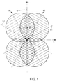
- the characteristic diagram shown in FIG. 1 is a diagram for two accelerometers, not shown, which are opposed to the Y direction, e.g. the direction of travel of a motor vehicle, are aligned in one plane at opposite angles 4) 1 or ⁇ 1> 2, which in this case are ⁇ 30 in this case.
- the main sensitivity axes of the accelerometers are designated A1 and A2.
- the planes of symmetry E1 and E2 perpendicular to the plane of the drawing for the two accelerometers are also drawn perpendicular to these axes.
- the transducer characteristics are spherically symmetrical in the positive and negative directions, the four spheres seen here as circles each running through the zero point of the X-Y coordinate system.
- the characteristic diagrams are hatched for the transducer 1 with the main sensitivity axis A1 perpendicular to it, for the transducer 2 with the main sensitivity axis A2 perpendicular to this.
- the characteristic diagrams overlap in the cross-hatched areas.
- This evaluation circuit shows an evaluation circuit for the signals a1 and a2 of the accelerometers in a mixed analog-digital version.
- This evaluation circuit consists of a selection circuit 11 and a logic 12.
- the selection circuit in this case is a maximum value circuit and has two differential amplifiers 13 and 14 as input elements, the signal a1 being the negative input of the differential amplifier 13 and the positive input of the differential amplifier 14 is supplied.
- the signal a2 is fed to the positive input of the differential amplifier 13 and the negative input of the differential amplifier 14.
- the differential amplifiers 13 and 14 each control a switch 15 or 16 between two positions, the signal a1 in one position and the signal a2 in the other position being forwarded via the center contact for further evaluation.
- the two inputs of the differential amplifiers are each connected to the two switch contacts of the two switches.
- the center contact of the switch 15 is connected to the positive input of a further differential amplifier 17 and at the same time to a switch contact of a further switch 18.
- the center contact of the second switch 16 is connected on the one hand to the second switch contact of the switch 18 and on the other hand via an inverter 19 to the negative input of the differential amplifier 17.
- the selected signal a is then present at the center contact of the last switch 18 and a sign signal V for the selected signal a is present at the output of the last differential amplifier 17. These two signals are fed to the logic 12 and can be treated there according to further criteria.
- the circuitry of the differential amplifier 13 can be referred to as the maximum value circuit, that of the differential amplifier 14 as the minimum value circuit. If signal a1 is greater than signal a2, switch 15 is in the position shown in FIG. the signal a1 is forwarded via the center contact of the switch 15. The smallest signal, in this case the signal a2, is selected by the differential amplifier 14 and passed on via the center contact of the switch 16. In order to obtain the same sign on the input side of the differential amplifier 17, the inverter 19 is connected downstream of the switch 16. In this case, since the signal a1 is the larger signal, this is fed to the logic via the last switch 18; one sees immediately that in this case a positive signal is obtained as the sign signal.
- FIGS. 5 to 9 By means of appropriate selection criteria for the function of the differential amplifiers and switches, specific characteristic curves according to FIGS. 5 to 9 can be achieved from the overall characteristic diagram according to FIG. 1, all of which apply to an arrangement with two accelerometers.
- the acceleration sensors are arranged at angles of ⁇ 30 relative to the direction of travel Y as in FIG. 1, in FIG. 6 this angle is 45 ° and in FIG. 7 ⁇ 15 °.
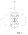
- the characteristic curve program according to FIG. 8 is obtained from the diagrams of two accelerometers, which are arranged in one plane at an angle of 90 to each other.
- the transducer characteristics are not the same here.
- the full characteristic diagrams of each accelerometer are the double circles along the main sensitivity axes A1 and A2, whereby these double circles are again to be thought of as rotationally symmetrical about these axes. It can be seen that the radii of these double circles and the radii of the balls are not the same.
- subtracting and adding certain areas of the characteristic diagrams can be hidden, so that the two opposite spherical triangles remain effective for the evaluation of accelerations.
- FIG. 3 shows a maximum value circuit in a mixed analog-digital version for three signals a1, a2 and a3 of three accelerometers, not shown.
- the signals a1 and a2 of the two first pickups are fed via a series resistor to the negative or positive input of a differential amplifier 21 and at the same time to the two switching contacts of a switch 22.
- the center contact of this switch is connected to the negative input of a further differential amplifier 23, the positive input of which is fed to signal a3.
- the series resistors and capacitors shown are used for adaptation.
- This signal a3 is supplied to a switch contact of a further switch 24 connected downstream of the differential amplifier 23, to the other switch contact of which the center contact of the switch 22 is connected.
- the center contact of this last switch 24 is connected to an output terminal 25 of this maximum value circuit. From the position of the switches 22 and 24 it can be seen directly that the signal a2 is the largest signal in this case and is forwarded to the output 25 of the circuit.
- FIG. 4 A variant of a further maximum value circuit in a mixed analog-digital version for three input signals a1, a2 and a3 is shown in FIG.
- the circuit structure in turn has two differential amplifiers 31 and 33 for comparing the signals a1 and a2 or the signal a3 and the comparison signal evaluated in the differential amplifier 31.
- the differential amplifiers 31 and 33 are each followed by a switch 32 or 34 corresponding to the switches 22 and 24 in FIG. 3.
- the output of the circuit is designated 35.
- the difference of this circuit arrangement according to FIG. 4 is that all signals a1, a2 and a3 are each fed to a preamplifier 36, 37 and 38, respectively, which additionally define a lower threshold value. Otherwise, the evaluation is the same as in the exemplary embodiment for FIG. 3.
- FIGS. 9 and 10 a transducer arrangement comprising three acceleration transducers can be connected, the characteristic diagram of which is shown in FIGS. 9 and 10.
- the main sensitivity axis A1 of the first accelerometer, not shown, is inclined at an angle of -30 to the direction of travel y in the horizontal plane
- the main sensitivity axis A2 of the second accelerometer lies in the (-x) direction
- the main sensitivity axis A3 also lies in the horizontal plane opposite the direction of travel y at an angle of -1500.
- FIG. 10 shows a section in a plane perpendicular to the main sensitivity axis A2, from which the spherical symmetry of the characteristic diagrams again emerges.
- FIG. 11 shows a programmable circuit arrangement for digitally evaluating the output signals from n accelerometers.
- the output signals a1, a2,... On the individual accelerometers are fed to a changeover switch 41 without or with an n-fold sample and hold function.
- the microprocessor 43 calls up the output signal which is to be digitized by the circuit 42 and made available to the microprocessor 43.
- the microprocessor 43 accepts the signals digitized and provided by the circuit 42 and processes them with the aid of a program part (software) which operates in accordance with the requirements of the claims. Other parts of the overall program perform different tasks.
- circuit elements described are of course exemplary.
- the circuits can or the like by other electronic modules. are replaced, provided that only the same or similar circuit function is fulfilled, which is predetermined by a fixed or programmable software.
Landscapes
- Engineering & Computer Science (AREA)
- Mechanical Engineering (AREA)
- Physics & Mathematics (AREA)
- General Physics & Mathematics (AREA)
- Air Bags (AREA)
- Indicating Or Recording The Presence, Absence, Or Direction Of Movement (AREA)
- Navigation (AREA)
- Position Input By Displaying (AREA)
- Gyroscopes (AREA)
- Switches Operated By Changes In Physical Conditions (AREA)
Claims (8)
Applications Claiming Priority (2)
| Application Number | Priority Date | Filing Date | Title |
|---|---|---|---|
| DE19873733837 DE3733837A1 (de) | 1987-10-07 | 1987-10-07 | Schaltungsanordnung zum erfassen von beschleunigungen |
| DE3733837 | 1987-10-07 |
Publications (4)
| Publication Number | Publication Date |
|---|---|
| EP0311039A2 EP0311039A2 (fr) | 1989-04-12 |
| EP0311039A3 EP0311039A3 (fr) | 1991-01-16 |
| EP0311039B1 true EP0311039B1 (fr) | 1993-01-07 |
| EP0311039B2 EP0311039B2 (fr) | 1996-02-21 |
Family
ID=6337768
Family Applications (1)
| Application Number | Title | Priority Date | Filing Date |
|---|---|---|---|
| EP88116465A Expired - Lifetime EP0311039B2 (fr) | 1987-10-07 | 1988-10-05 | Circuit électrique de détection des accélérations |
Country Status (2)
| Country | Link |
|---|---|
| EP (1) | EP0311039B2 (fr) |
| DE (2) | DE3733837A1 (fr) |
Families Citing this family (11)
| Publication number | Priority date | Publication date | Assignee | Title |
|---|---|---|---|---|
| DE4116336C1 (en) * | 1991-05-18 | 1992-06-11 | Messerschmitt-Boelkow-Blohm Gmbh, 8012 Ottobrunn, De | Passive safety device release assembly for motor vehicle occupant - has acceleration pick=ups with sensitivity axes directed to detect angle of frontal impact and supplying evaluating circuit |
| US5758899A (en) * | 1995-06-15 | 1998-06-02 | Trw Inc. | Method and apparatus for providing a safing function for side impact crash sensing systems |
| DE19619412C1 (de) * | 1996-05-14 | 1997-08-28 | Telefunken Microelectron | Auslöseverfahren für passive Sicherheitseinrichtungen in Fahrzeugen |
| DE19619414C1 (de) * | 1996-05-14 | 1997-08-21 | Telefunken Microelectron | Auslöseverfahren für passive Sicherheitseinrichtungen in Fahrzeugen |
| DE19715575C1 (de) * | 1997-04-15 | 1998-09-24 | Telefunken Microelectron | Verfahren zur richtungsselektiven Ausrichtung einer passiven Sicherheitseinrichtung |
| DE19939984C2 (de) * | 1999-08-24 | 2001-09-13 | Daimler Chrysler Ag | Verfahren zur richtungsselektiven Ausrichtung einer passiven Sicherheitseinrichtung |
| DE10002471A1 (de) | 2000-01-21 | 2001-07-26 | Daimler Chrysler Ag | Verfahren zum Betreiben einer Sensorbaugruppe mit richtungsempfindlichen Sensoren sowie entsprechende Beschleunigungsaufnehmergruppe |
| DE10325135A1 (de) * | 2003-06-04 | 2004-12-23 | Conti Temic Microelectronic Gmbh | Verfahren zur näherungsweisen Ermittlung eines Richtungswinkels sowie Insassenschutzsystem |
| GB2403935A (en) | 2003-07-17 | 2005-01-19 | Autoliv Dev | Crash detection system with accelerometers at an angle to a vehicles longitudinal axis |
| DE10335169A1 (de) * | 2003-07-30 | 2005-02-24 | Conti Temic Microelectronic Gmbh | Sensoranordnung für ein Kraftfahrzeug zum Erkennen eines Aufpralls, sowie ein dazugehörendes Auswerteverfahren für ein Insassenschutzsystem in einem Fahrzeug |
| DE112004000664D2 (de) | 2003-07-30 | 2005-12-22 | Conti Temic Microelectronic | Vorrichtung und Verfahren zur Messung von Beschleunigungen für ein Fahrzeug-Insassenschutzsystem |
Family Cites Families (7)
| Publication number | Priority date | Publication date | Assignee | Title |
|---|---|---|---|---|
| US3701903A (en) * | 1970-10-29 | 1972-10-31 | Honeywell Inc | Piezoelectric vehicle impact sensor |
| DE2207831A1 (de) * | 1972-02-19 | 1973-08-23 | Dynamit Nobel Ag | Elektronischer sensor zum ausloesen von sicherheitseinrichtungen beim aufprall von fahrzeugen |
| US3980318A (en) * | 1974-04-15 | 1976-09-14 | Eaton Corporation | Fused multiple stage inflation system |
| JPS5327933A (en) * | 1976-08-24 | 1978-03-15 | Honda Motor Co Ltd | Automotive air-bag activating apparatus |
| DE3001780C2 (de) * | 1980-01-18 | 1984-09-27 | Becker Autoradiowerk Gmbh, 7516 Karlsbad | Steueranordnung für Sicherheitseinrichtungen in Fahrzeugen |
| GB2146776B (en) * | 1983-09-16 | 1986-07-30 | Ferranti Plc | Accelerometer systems |
| DE3717427C3 (de) * | 1987-05-23 | 1994-09-01 | Deutsche Aerospace | Aufprallsensor für Kraftfahrzeuge |
-
1987
- 1987-10-07 DE DE19873733837 patent/DE3733837A1/de active Granted
-
1988
- 1988-10-05 DE DE8888116465T patent/DE3877308D1/de not_active Expired - Fee Related
- 1988-10-05 EP EP88116465A patent/EP0311039B2/fr not_active Expired - Lifetime
Also Published As
| Publication number | Publication date |
|---|---|
| DE3733837A1 (de) | 1989-04-27 |
| EP0311039A2 (fr) | 1989-04-12 |
| EP0311039B2 (fr) | 1996-02-21 |
| EP0311039A3 (fr) | 1991-01-16 |
| DE3877308D1 (de) | 1993-02-18 |
| DE3733837C2 (fr) | 1990-05-23 |
Similar Documents
| Publication | Publication Date | Title |
|---|---|---|
| EP0292669B1 (fr) | Détecteur de collision pour les véhicules automobiles | |
| EP0311039B2 (fr) | Circuit électrique de détection des accélérations | |
| EP0980323B1 (fr) | Dispositif pour commander un moyen de protection des occupants d'un vehicule automobile | |
| DE60011458T2 (de) | Vorrichtung und verfahren zur bestimmung von koordinaten und orientierung | |
| EP0342401A2 (fr) | Dispositif pour déclencher un système de sécurité passif | |
| DE3801514C2 (fr) | ||
| EP2509828A1 (fr) | Procédé et boîtier de commande pour la détermination du type d'une collision d'un véhicule | |
| DE602004006136T2 (de) | Eine Crashsensor Anordnung | |
| EP0918668A1 (fr) | Dispositif de liberation de moyens de retenue dans un vehicule a moteur | |
| DE3920091A1 (de) | Sicherheitseinrichtung fuer fahrzeuginsassen | |
| EP0935493B1 (fr) | Dispositif pour agir sur la qualite de conduite de vehicules en modeles reduits telecommandes | |
| WO1996039315A1 (fr) | Dispositif de commande pour declencher un dispositif de retenue sur un vehicule en cas de choc lateral | |
| DE19537546A1 (de) | Aufprallerkennungsvorrichtung, insbesondere für ein Sicherheitssystem für Fahrzeuge zur Personenbeförderung | |
| EP1140564B1 (fr) | Systeme de commande pour moyens de protection pour passagers d'une automobile | |
| DE3816588A1 (de) | Einrichtung zur ausloesung einer passiven sicherheitseinrichtung | |
| DE3606567A1 (de) | Pruefverfahren fuer airbag-system-ausloeseschaltungen | |
| EP1648745B1 (fr) | Dispositif et procede de mesure d'accelerations pour systeme de protection d'occupant de vehicule | |
| DE19753163A1 (de) | Verfahren und Vorrichtung zur Bildung eines Auslösekriteriums für ein Rückhaltesystem | |
| WO2000029263A1 (fr) | Systeme de commande comportant trois capteurs d'acceleration pour un dispositif de protection d'un occupant de vehicule automobile | |
| DE19725058A1 (de) | Vorrichtung mit redundanten Kanälen zwischen einer Sensoreinrichtung und einer Auswerteeinrichtung | |
| DE10121391C5 (de) | Vorrichtung zur Beschleunigungsmessung | |
| DE10023503B4 (de) | Positionsschalter | |
| DE2917967A1 (de) | Einrichtung zur messung von kraftkomponenten, insbesondere an kraftfahrzeugen | |
| WO2009003434A1 (fr) | Véhicule équipé d'un système de protection des occupants | |
| DE102018219240A1 (de) | Drehratensensor und Vorrichtung mit einem Drehratensensor |
Legal Events
| Date | Code | Title | Description |
|---|---|---|---|
| PUAI | Public reference made under article 153(3) epc to a published international application that has entered the european phase |
Free format text: ORIGINAL CODE: 0009012 |
|
| AK | Designated contracting states |
Kind code of ref document: A2 Designated state(s): DE FR GB IT SE |
|
| PUAL | Search report despatched |
Free format text: ORIGINAL CODE: 0009013 |
|
| AK | Designated contracting states |
Kind code of ref document: A3 Designated state(s): DE FR GB IT SE |
|
| 17P | Request for examination filed |
Effective date: 19901214 |
|
| 17Q | First examination report despatched |
Effective date: 19911126 |
|
| GRAA | (expected) grant |
Free format text: ORIGINAL CODE: 0009210 |
|
| RAP1 | Party data changed (applicant data changed or rights of an application transferred) |
Owner name: DEUTSCHE AEROSPACE AKTIENGESELLSCHAFT |
|
| AK | Designated contracting states |
Kind code of ref document: B1 Designated state(s): DE FR GB IT SE |
|
| PG25 | Lapsed in a contracting state [announced via postgrant information from national office to epo] |
Ref country code: IT Free format text: LAPSE BECAUSE OF FAILURE TO SUBMIT A TRANSLATION OF THE DESCRIPTION OR TO PAY THE FEE WITHIN THE PRE;WARNING: LAPSES OF ITALIAN PATENTS WITH EFFECTIVE DATE BEFORE 2007 MAY HAVE OCCURRED AT ANY TIME BEFORE 2007. THE CORRECT EFFECTIVE DATE MAY BE DIFFERENT FROM THE ONE RECORDED.SCRIBED TIME-LIMIT Effective date: 19930107 Ref country code: FR Effective date: 19930107 Ref country code: GB Effective date: 19930107 Ref country code: SE Effective date: 19930107 |
|
| REF | Corresponds to: |
Ref document number: 3877308 Country of ref document: DE Date of ref document: 19930218 |
|
| EN | Fr: translation not filed | ||
| GBV | Gb: ep patent (uk) treated as always having been void in accordance with gb section 77(7)/1977 [no translation filed] |
Effective date: 19930107 |
|
| PLBI | Opposition filed |
Free format text: ORIGINAL CODE: 0009260 |
|
| 26 | Opposition filed |
Opponent name: ROBERT BOSCH GMBH Effective date: 19930723 |
|
| RAP2 | Party data changed (patent owner data changed or rights of a patent transferred) |
Owner name: TEMIC TELEFUNKEN MICROELECTRONIC GMBH |
|
| PUAH | Patent maintained in amended form |
Free format text: ORIGINAL CODE: 0009272 |
|
| STAA | Information on the status of an ep patent application or granted ep patent |
Free format text: STATUS: PATENT MAINTAINED AS AMENDED |
|
| 27A | Patent maintained in amended form |
Effective date: 19960221 |
|
| AK | Designated contracting states |
Kind code of ref document: B2 Designated state(s): DE FR GB IT SE |
|
| EN | Fr: translation not filed | ||
| PGFP | Annual fee paid to national office [announced via postgrant information from national office to epo] |
Ref country code: DE Payment date: 19961203 Year of fee payment: 9 |
|
| PG25 | Lapsed in a contracting state [announced via postgrant information from national office to epo] |
Ref country code: DE Free format text: LAPSE BECAUSE OF NON-PAYMENT OF DUE FEES Effective date: 19980701 |