EP0311097A2 - Steuerungsapparat für die Brennstoff-Verbrennung einer Maschine - Google Patents
Steuerungsapparat für die Brennstoff-Verbrennung einer Maschine Download PDFInfo
- Publication number
- EP0311097A2 EP0311097A2 EP88116648A EP88116648A EP0311097A2 EP 0311097 A2 EP0311097 A2 EP 0311097A2 EP 88116648 A EP88116648 A EP 88116648A EP 88116648 A EP88116648 A EP 88116648A EP 0311097 A2 EP0311097 A2 EP 0311097A2
- Authority
- EP
- European Patent Office
- Prior art keywords
- map
- highoctane
- engine
- regular
- ignition advance
- Prior art date
- Legal status (The legal status is an assumption and is not a legal conclusion. Google has not performed a legal analysis and makes no representation as to the accuracy of the status listed.)
- Granted
Links
Images


Classifications
-
- F—MECHANICAL ENGINEERING; LIGHTING; HEATING; WEAPONS; BLASTING
- F02—COMBUSTION ENGINES; HOT-GAS OR COMBUSTION-PRODUCT ENGINE PLANTS
- F02P—IGNITION, OTHER THAN COMPRESSION IGNITION, FOR INTERNAL-COMBUSTION ENGINES; TESTING OF IGNITION TIMING IN COMPRESSION-IGNITION ENGINES
- F02P5/00—Advancing or retarding ignition; Control therefor
- F02P5/04—Advancing or retarding ignition; Control therefor automatically, as a function of the working conditions of the engine or vehicle or of the atmospheric conditions
- F02P5/145—Advancing or retarding ignition; Control therefor automatically, as a function of the working conditions of the engine or vehicle or of the atmospheric conditions using electrical means
- F02P5/15—Digital data processing
- F02P5/152—Digital data processing dependent on pinking
- F02P5/1527—Digital data processing dependent on pinking with means allowing burning of two or more fuels, e.g. super or normal, premium or regular
-
- Y—GENERAL TAGGING OF NEW TECHNOLOGICAL DEVELOPMENTS; GENERAL TAGGING OF CROSS-SECTIONAL TECHNOLOGIES SPANNING OVER SEVERAL SECTIONS OF THE IPC; TECHNICAL SUBJECTS COVERED BY FORMER USPC CROSS-REFERENCE ART COLLECTIONS [XRACs] AND DIGESTS
- Y02—TECHNOLOGIES OR APPLICATIONS FOR MITIGATION OR ADAPTATION AGAINST CLIMATE CHANGE
- Y02T—CLIMATE CHANGE MITIGATION TECHNOLOGIES RELATED TO TRANSPORTATION
- Y02T10/00—Road transport of goods or passengers
- Y02T10/10—Internal combustion engine [ICE] based vehicles
- Y02T10/40—Engine management systems
Definitions
- the present invention relates to a fuel combustion control apparatus for an engine mounted on an automotive vehicle, for instance, and more specifically to a fuel combustion control apparatus by which ignition timings (advance angles) can be determined on the basis of two, regular and highoctane, maps.
- the fuel octane rating (number) is an index indicative of fuel antiknocking property.
- highoctane gasoline is advantageous because it is possible to increase combustion speed as fast as possible and advance ignition timing as early as possible as long as the engine is operating without producing knocking.
- highoctane vehicles there are automotive vehicles on which an engine designed for highoctane gasoline is mounted (referred to as highoctane vehicles).
- regular gasoline is used erroneously or unavoidably, there exists a problem in that a sufficient engine output power determined on the basis of highoctane gasoline is not generated or knocking is often produced and therefore the engine characteristics are deteriorated.
- regular vehicles when highoctane gasoline is used for an automotive vehicle on which an engine designed for regular gasoline is mounted (referred to as regular vehicles), it is impossible to effectively utilize the antiknocking characteristics of the highoctane gasoline.
- a control map represents appropriate relationship between ignition timings (advance angles) and engine speeds.
- a fuel combustion control apparatus for an engine comprises: (a) first detecting means for detecting engine operation conditions; (b) second detecting means for detecting engine knocking; (c) storing means, coupled to said first detecting means, for storing a regular map indicative of basic ignition advance angles with respect to engine operating conditions in use of regular gasoline, a highoctane map indicative of basic ignition advance angles with respect to engine operating conditions in use of highoctane gasoline, a reference map switching line indicative of standard ignition advance angles with respect to engine operating conditions along which the regular map is switched to the highoctane map, and a maximum highoctane map retard angle line with respect to engine operating conditions along which the highoctane map is switched to the regular map; (d) first commanding means, coupled to said first and second detecting means, for incrementing a current ignition advance angle in use of the regular map when said first detecting means detects operating conditions within a predetermined switching range and said second detecting
- a method of determining engine ignition advance angles on the basis of a regular map or a highoctane map comprises: (a) checking whether engine speed lies within a predetermined switching range; (b) if engine speed lies out of the switching range, selecting the regular map; (c) if engine speed lies within the predetermined switching range, checking whether engine knocking is present or absent; (d) if present, decrementing the current ignition advance angle; and if absent, incrementing a current ignition advance angle; (e) checking whether the ignition advance angle is equal to or larger than a reference map switching line indicative of standard ignition advance angles with respect to engine speeds along which the regular map is switched to the highoctane map; (f) if smaller than the reference map switching line, selecting the regular map; (g) if equal to or larger than the reference map switching line, checking whether the ignition advance angle is equal to or larger than the maximum highoctane map retard angle line with respect to engine speeds along which the
- the ignition timing advance angle is incremented in the regular map as long as knocking is absent and the regular map is switched to the highoctane map only when the incremented advance angle is equal to or larger than the reference map switch angle and the maximum highoctane map retard angle simultaneously at each engine speed, therefore, once switched, fuel combustion control operation is effected on the basis of the switch highoctane map without producing map hunting.
- the current advance angle is decremented, and the highoctane map is switched to the regular map when the advance angle is smaller than the maximum highoctane map retard angle.
- Fig. 1 is a basic schematic block diagram of the control apparatus for an engine according to the present invention.
- the apparatus comprises engine operating condition detecting means a for detecting engine operating conditions; knocking detecting means b for detecting a presence of engine knocking; a map storing means c for storing a regular map indicative of basic ignition advance angles with respect to engine operating conditions in use of regular gasoline, a highoctane map indicative of basic ignition advance angles with respect to engine operating conditions in use of highoctane gasoline, a reference map switching line indicative of standard ignition advance angles with respect to engine operating conditions along which the regular map is switched to the highoctane map, and a maximum highoctane map retard angle line with respect to the engine operating conditions along which the highoctane map is switched to the regular map; first commanding means d , for incrementing a current ignition advance angle in use of the regular map when said first detecting means detects operating conditions within a predetermined switching range and said second detecting means detects no knocking, and
- ignition timing is advanced at a predetermined advance angle rate in the regular map and then switched to the highoctane map only when the advance angle is equal to or larger than the reference map switching value and the maximum highoctane map retard angle value simultaneously. Therefore, once the map has been switched, combustion control is made on the basis of the highoctane map as long as knocking is not produced, so that it is possible to prevent hunting between the two maps for providing better control stability.
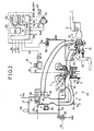
- Fig. 2 shows an embodiment of the controlling apparatus of the present invention.
- intake air is supplied to each cylinder by way of an air cleaner 2, an intake pipe 3, a throttle chamber 4, and an intake manifold 5 including a main port 6 and a subport 7 corresponding to each engine cylinder.
- fuel is injected through an injector 8 on the basis of fuel injection signals S i .
- Each cylinder is provided with an ignition plug 9 to which a high tension pulse signal P i is supplied from an ignition coil 10 and a power transistor unit 11.
- ignition coil 10 and the power transistor unit 11 generate a high tension pulse signal P i on the basis of an ignition signal S p outputted from the control unit 50 in accordance with a predetermined ignition timing, and supply this signal S p to the ignition plug 9.
- the above ignition plug 9, the ignition coil 10 and the power transistor unit 11 constitute combustion effecting means for effecting fuel combustion.
- ignition timing is controlled, it is also possible to control an amount of fuel to be injected, a turbo charger pressure, etc. Once ignited, a mixture gas introduced into the cylinder is ignited, exploded in response to the high tension pulse P i and then exhausted through an exhaust pipe 13.
- a compressor 22 of a tube charger 21 is connected to the intake pipe 3, and this compressor 22 is connected to a turbine 23 disposed in the exhaust pipe 13.
- This turbo charger 21 is driven by exhaust gas to drive the turbine 23, so that intake air is supercharged by the compressor 22 connected to the turbine 23.
- This turbo charger pressure of the turbo charger 21 can be adjusted by a swing valve 24 and a swing valve controller 25. Pressure to control the swing valve controller 25 can be adjusted by a turbo charger pressure control solenoid valve 26 actuated in response to a turbo charger pressure control signal S k .
- a throttle valve 27 is disposed within the throttle chamber 4 on the downstream side of the turbo charger 21.
- the amount of intake air is controlled by the throttle valve 27.
- the amount of intake air is controlled by an ACC valve 29 and an FICD solenoid valve 30 provided in a bypass passage 28 communicating between the upstream side and the lower stream side of the throttle valve 27.
- the opening rate of this ACC valve 29 is adjusted in response to idling speed control signal S A to control the amount of intake air so that the engine idling speed is maintained at a target value.
- the FICD solenoid valve 30 is opened when a predetermined auxiliary machine (e.g. air conditioning system) is actuated to increase the amount of intake air by a predetermined amount so that the engine idling speed is increased to a predetermined speed.
- a predetermined auxiliary machine e.g. air conditioning system
- an air regulator 31 connected between the upstream side and the downstream side of the throttle valve 27 introduces atmospheric air on the upstream side of the throttle valve 27 to the downstream side thereof to always keep fuel pressure applied to the injector 8 at a constant level.
- An intake relief value 32 serves to relieve intake air within the throttle chamber 4 to the air, when the intake air pressure (the turbo charger pressure) within the throttle chamber 4 rises abnormally high, to reduce the turbo charger pressure down to a safety pressure.
- the intake air within the throttle chamber 4 branches from the intake manifold 5 into the main port 6 and the subport 7.
- a power valve 34 opened/closed by a variable intake air control actuator 33 is disposed within the main port 6 formed with a relatively large aperture.
- a control vacuum is supplied from a variable intake air control solenoid valve 36 via a delay valve 35.
- This variable intake air control solenoid valve 36 leaks the intake vacuum on the downstream side of the throttle valve 27, introduced via the check valve 37 and the vacuum tank 38, to the air on the basis of the power valve switching signal S V , in order to adjust the control vacuum supplied to the variable intake air control actuator 33.
- the variable intake air control actuator 33 opens/closes a power valve 34 in response to the adjusted control vacuum.
- the subport 7 is smaller in diameter and longer in length as compared with the main port 6.
- the power valve 34 is closed, so that the intake air flows through the subport 7. Accordingly, the speed of the intake air is increased; the charging efficiency is increased; and the engine torque is increased.
- the power valve 34 is opened, so that the intake air flows through both the main port 6 and the subport 7. Accordingly, the resistance in intake air flow is decreased; and the engine output is increased.
- the engine operating conditions can be detected by various sensors.
- the opening rate TVO of the throttle valve 27 is detected by a throttle sensor 41;
- the coolant temperature TW is detected by a coolant temperature sensor 42:
- a presence of engine knocking vibration V E is detected by a knocking sensor (knocking detecting means) 43;
- an engine crank angular position is detected by a crank angle sensor 44.
- the crank angle sensor 44 outputs an angle unit (1 degree) signal CA corresponding to one-degree crank angle and a cylinder reference signal Ref for distinguishing each cylinder.
- the above throttle sensor 41, the coolant temperature sensor 42 and the crank angle sensor 44 constitutes engine operating condition detecting means 45.
- a control unit 50 shown in Fig. 2 functions as map storing means c , the first commanding means d , the second commanding means e , and the calculating means f , which is composed of a CPU 51, a ROM 52, a RAM 53 and an I/O port 54.
- the CPU 51 receives external data required via the I/O port in accordance with a program stored in the ROM 52 and transfers data between the ROM 52 and the RAM 53 to calculate values required for controlling engine combustion.
- the calculated data are outputted via the I/O port 54 where necessary.
- a physical value to be controlled is detected, and a difference between the detected physical value and a target value is reduced by correcting an object to be controlled.
- the target values in a feedback control system are determined in the form of a three dimensional maps for instance under due consideration of practical external disturbance factors against the object to be controlled.
- two, regular and highoctane, gasoline are supplied
- two different, regular and highoctane, maps are formed, respectively to reduce the map scale by reducing the number of mapping addresses and by effectively utilizing the memory areas. This is because when a single map taking into account all the factors of both the gasolines is formed, the map scale is extraordinarily increased.
- either one of regular or highoctane gasoline is always supplied to the engine and the two gasolines will not be changed whenever the vehicle is refueled. Furthermore, once refueled, the same gasoline is used continually until the next refuelling.
- a regular map and a highoctane map are formed separately to reduce the map scale.
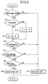
- Fig. 3 shows a control flowchart for assistance in explaining the fuel combustion control operation of the present invention, which is stored in the RAM 53 and executed at predetermined time intervals in dependence upon timer interruption operation.
- Control first discriminates whether the engine operating conditions lie within a predetermined switching range (in process P1).
- This switching range is an engine speed range from about 2000 to 3000 rpm, for instance in this embodiment as shown in Fig. 4.
- This switching engine speed is set to an appropriate range according to the type of engine. Further, an amount of fuel to be injected can be determined as this switching range.
- ignition timing signals S p are outputted to ignite the mixture.
- a predetermined advance angle value e.g.
- Control discriminates whether the advance angle value ⁇ corrected toward an advance or retard angle side is equal to or larger than the reference map switching line value (in process P6). If NO, control selects the regular specifications (in process P2). If YES, control further discriminates whether the advance angle value ⁇ corrected toward an advance or retard angle side is equal to or larger than the maximum highoctane map retard line value (in process P7). If NO, control selects the regular specifications (in process P2).
- the maximum highoctane map retard angle line is formed as a map by measuring ignition timings on the maximum retard angle side controllable at each engine speed when highoctane rating fuel is used for an engine.
- the reference map switching line is determined a uniform advance angle width away from the regular map on the basis of experiments, both as depicted in Fig. 4. Therefore, there exists a range where the maximum highoctane map retard angle line is set on the advance angle side beyond the reference map switching line at higher engine speed range.
- the regular map is simply switch to the highoctane map when the advance angle of ignition timing increases beyond the reference map switching line, and further the highoctane map is simply switched to the regular map when the advance angle decreases below the maximum highoctane map retard angle line. Therefore, in the prior-art apparatus, since the regular map is simply switched to the highoctane map even in a range where the advance angle is higher than the reference map switching line but lower than the maximum highoctane map retard angle line, the highoctane map is returned to the regular map at the succeeding processing, thus resulting in hunting operation.
- control checks whether or predetermined time has elapsed after the advance angle exceeds both the reference map switching line and the maximum highoctane map retard angle line (in process P8). If NO, control selects the regular map (in process P2). In the present invention, since the advance angle correction as explained in process P4 is repeated whenever this control program is executed, the advance angle ⁇ is advanced step by step. Therefore, after a predetermined time has elapsed, since control determines YES (in process P8), the highoctane specifications are selected (in process P9).
- a basic advance angle ADV H according to the current operating conditions is selected in look-up method from the highoctane map.
- this selected advance angle ADV H is used as it is. If knocking is present, calculation is made to retard this advance angle ADV H . Thereafter, control checks the switching conditions from the highoctane map to the regular map as follows: If knocking occurs frequently in the highoctane map, the basic advance angle ADV H is retarded step by step. When the retarded basic advance angle is retarded down to the maximum highoctane map retard angle line, the highoctane map is switched to the regular map.
- ADV H denotes basic ignition timings looked up from a highoctane map
- BETA denotes map correction values such as a retard angle correction value of a knocking control, etc.
- ignition timing signals S p are outputted to ignite the mixture on the basis of the final calculated ignition timing ADV i .
- Fig. 4 shows the relationship between engine speeds and ignition timings represented by advance angles, in which there are described a line indicative of the highoctane map, a line indicative of the regular map, a reference map switching line at which the regular map is switched to the highoctane map and a maximum highoctane map retard angle line at which the highoctane map is switched to the regular map.
- the ignition timing is advanced to a point A in Fig. 4.
- the regular specifications are maintained in the same way as in the prior-art apparatus.
- the ignition timing is further advanced to a point B, since this point is still below the reference map switching line, the regular specifications are maintained in the same way as in the prior-art apparatus.
- the ignition timings are controlled on the basis of the highoctane map immediately after the engine has been started.
- the ignition timings are controlled on the basis of the regular map immediately after the engine has been started. That is, the kind of fuel (highoctane or regular gasoline) can be determined on the basis of occurrence of knocking produced immediately after the engine has been started to select an appropriate map. Therefore, either of highoctane or regular gasoline can be used in both the highoctane and regular vehicles.
- the regular map is used at the start of a regular vehicle, when highoctane gasoline is used for the regular vehicle, the ignition timing is determined on the basis of the regular map, and the regular map is switched to the highoctane map after the ignition timing has been advanced repeatedly. Therefore, it is impossible to utilize the function of the highoctane gasoline or to increase the engine output at the start of the engine.
- the map used immediately before the engine is stopped is checked, stored during engine stop, and used again immediately after the engine is started again. That is, since an appropriate map according to the fuel can be selected immediately after engine start, it is possible to improve the engine performance immediately after the engine has been started.
- the apparatus of the present invention further comprises engine start/stop detecting means i for detecting engine start and engine stop, and third commanding means h for checking the map used immediately before the engine is stopped, holding the checked map while the engine is stopped and generating a third command to the calculating means to use the held map again immediately after the engine has been started again.
- an ignition switch 46 is connected to the control unit 50 via the I/O port.
- an engine start/stop signal ENG ON/OFF is outputted from the ON terminal.
- This engine start/stop signal is at a high-voltage level when the engine is started and at a low-voltage level when the engine is stopped.
- This ignition switch 46 severs as engine start/stop detecting means. Further, it is also possible to output an engine start signal from START terminal and an engine stop signal from ACC terminal of the ignition key switch 46. Further, engine start/stop can be detected on the basis of change in the unit (1°) signal CA outputted from the crank angle sensor 44.
- the third commanding means is incorporated in the control unit 50.
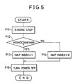
- Fig. 5 shows a flowchart stored in the ROM 52 in the control unit 50 and called “after program” executed after engine stop. Further, Fig. 6 shows a flowchart called "before program” executed before engine start.
- map index when the map index is set (in process P13 or P14), a predetermined memory error index is set to "1". These map index and the memory error index are stored in predetermined addresses in the RAM 53 even after the ignition key switch has been turned off (because backuped by the battery). Thereafter, control proceeds to the next step to turn off the power of the control unit 50 (in process P15). Therefore, since the map index is stored by battery backup operation even during engine stop, the map used before engine stop is stored in the form of an index, where "1" indicates the highoctane map and "0" indicates the regular map, for instance.
- control when control detects engine start on the basis of the engine start/stop signal ENG ON/OFF (in process P21), control checks whether "1" is set to the memory error index (in process P22). That is to say, when power supply to the battery backup area of the RAM 53 is turned off at engine stop or start due to some reason, since the memory error index (which has been set to "1” by the "after program")is reset to "0", it is possible to discriminate that the battery backup area is well kept activated to store a correct map index. If NO (in process P22), since this indicates that power supply to the battery backup area is turned off, control selects the regular map without reference to the map index (in process P23).
- control advances the ignition timing by a predetermined advance angle step by step.
- control determines that the vehicle is highoctane vehicle (in process P23) and executes the highoctane control (in process P24).
- control determines that the vehicle is regular vehicle (in process P23), and executes the regular control (in process P25).
- process P23 it is possible to simply determine whether the vehicle is highoctane vehicle or regular vehicle to select any one of highoctane control (map) or regular control (map).
- control checks whether the map index held at the battery backup area is "1" (in process P26). If YES, the map used for the preceding engine operation is the highoctane map, so that the fuel is of course highoctane fuel. Control executes the highoctane control (in process P24). If NO (in process P26), the map used for the preceding engine operation is the regular map, so that the fuel is of course regular fuel. Control executes the regular control (in process P25). Therefore, it is possible to select a map suitable for fuel to be used immediately after engine start. As a result, even if regular gasoline is used for the highoctane vehicle, knocking produced immediately after engine start can be prevented. Further,if highoctane gasoline is used for the regular vehicle, vehicle start performance can be improved immediately after engine start.
- the map used immediately before engine stop is checked, stored during engine stop, and used again immediately after engine restart, it is possible to always start the fuel combustion control on the basis of an appropriate map. Therefore, even if regular gasoline is used for a highoctane vehicle, knocking can be prevented. Even if highoctane gasoline is used for a regular vehicle, engine start performance can be improved by selecting a correct map according to fuel immediately after engine start.
Landscapes
- Engineering & Computer Science (AREA)
- Signal Processing (AREA)
- Chemical & Material Sciences (AREA)
- Combustion & Propulsion (AREA)
- Mechanical Engineering (AREA)
- General Engineering & Computer Science (AREA)
- Electrical Control Of Ignition Timing (AREA)
- Combined Controls Of Internal Combustion Engines (AREA)
Applications Claiming Priority (4)
| Application Number | Priority Date | Filing Date | Title |
|---|---|---|---|
| JP25349587A JPH0196473A (ja) | 1987-10-09 | 1987-10-09 | エンジンの燃焼制御装置 |
| JP253495/87 | 1987-10-09 | ||
| JP253494/87 | 1987-10-09 | ||
| JP25349487A JPH0196470A (ja) | 1987-10-09 | 1987-10-09 | エンジンの燃焼制御装置 |
Publications (3)
| Publication Number | Publication Date |
|---|---|
| EP0311097A2 true EP0311097A2 (de) | 1989-04-12 |
| EP0311097A3 EP0311097A3 (en) | 1989-06-07 |
| EP0311097B1 EP0311097B1 (de) | 1993-06-09 |
Family
ID=26541233
Family Applications (1)
| Application Number | Title | Priority Date | Filing Date |
|---|---|---|---|
| EP88116648A Expired - Lifetime EP0311097B1 (de) | 1987-10-09 | 1988-10-07 | Steuerungsapparat für die Brennstoff-Verbrennung einer Maschine |
Country Status (3)
| Country | Link |
|---|---|
| US (1) | US4903663A (de) |
| EP (1) | EP0311097B1 (de) |
| DE (1) | DE3881628T2 (de) |
Cited By (7)
| Publication number | Priority date | Publication date | Assignee | Title |
|---|---|---|---|---|
| GB2246816A (en) * | 1990-08-11 | 1992-02-12 | Honda Motor Co Ltd | I.C. engine ignition timing control |
| WO1997030286A1 (de) * | 1996-02-14 | 1997-08-21 | Daimler-Benz Aktiengesellschaft | Verfahren zur bestimmung des zündwinkels für eine brennkraftmaschine mit adaptiver klopfregelung |
| KR20040003826A (ko) * | 2002-07-04 | 2004-01-13 | 현대자동차주식회사 | 노크 학습치 갱신 방법 |
| EP2213871A1 (de) * | 2009-02-03 | 2010-08-04 | Robert Bosch Gmbh | Vorrichtung und Verfahren zur Klopfregelung in einem Verbrennungsmotor |
| FR2942006A1 (fr) * | 2009-02-11 | 2010-08-13 | Peugeot Citroen Automobiles Sa | Procede d'adaptation de l'avance a l'allumage d'un moteur a combustion interne |
| WO2010125260A1 (fr) * | 2009-04-30 | 2010-11-04 | Renault S.A.S. | Procede d'adaptation d'un moteur a l'indice de carburant par incrementation de l'indice d'octane appris du carburant |
| EP1602814A3 (de) * | 2004-06-04 | 2012-05-23 | Nissan Motor Co., Ltd. | Vorrichtung und Verfahren zur Regelung einer Brennkraftmaschine |
Families Citing this family (4)
| Publication number | Priority date | Publication date | Assignee | Title |
|---|---|---|---|---|
| JP2829161B2 (ja) * | 1991-09-18 | 1998-11-25 | 三菱電機株式会社 | 内燃機関の点火時期制御装置 |
| JPWO2006070459A1 (ja) * | 2004-12-28 | 2008-06-12 | ヤマハマリン株式会社 | 船舶用エンジンのノック制御装置 |
| US9541014B2 (en) * | 2014-11-21 | 2017-01-10 | Ford Global Technologies, Llc | Method for pre-ignition control |
| US9719436B2 (en) | 2014-11-21 | 2017-08-01 | Ford Global Technologies, Llc | Method for pre-ignition control in a pre-delivery phase |
Family Cites Families (6)
| Publication number | Priority date | Publication date | Assignee | Title |
|---|---|---|---|---|
| JPS58143169A (ja) * | 1982-02-17 | 1983-08-25 | Toyota Motor Corp | 点火時期制御方法 |
| JPS60116867A (ja) * | 1983-11-29 | 1985-06-24 | Mitsubishi Motors Corp | 内燃機関の点火時期制御装置 |
| JPH0718393B2 (ja) * | 1983-10-04 | 1995-03-06 | 三菱電機株式会社 | 内燃機関の点火時期制御装置 |
| US4612901A (en) * | 1984-03-07 | 1986-09-23 | Mitsubishi Denki Kabushiki Kaisha | Engine ignition timing control apparatus |
| JPS60212673A (ja) * | 1984-04-05 | 1985-10-24 | Nissan Motor Co Ltd | エンジンの点火時期制御装置 |
| DE3630907A1 (de) * | 1986-09-11 | 1988-04-28 | Audi Ag | Vorrichtung zur anpassung der gemischbildungseinrichtung und der zuendeinrichtung einer brennkraftmaschine fuer deren betrieb mit allen gaengigen otto-kraftstoffen |
-
1988
- 1988-10-07 DE DE8888116648T patent/DE3881628T2/de not_active Expired - Fee Related
- 1988-10-07 US US07/254,641 patent/US4903663A/en not_active Expired - Fee Related
- 1988-10-07 EP EP88116648A patent/EP0311097B1/de not_active Expired - Lifetime
Cited By (16)
| Publication number | Priority date | Publication date | Assignee | Title |
|---|---|---|---|---|
| GB2246816A (en) * | 1990-08-11 | 1992-02-12 | Honda Motor Co Ltd | I.C. engine ignition timing control |
| US5131369A (en) * | 1990-08-11 | 1992-07-21 | Honda Giken Kogyo Kabushiki Kaisha | Ignition timing control system for internal combustion engine |
| GB2246816B (en) * | 1990-08-11 | 1994-08-03 | Honda Motor Co Ltd | Ignition timing control system for internal combustion engine |
| WO1997030286A1 (de) * | 1996-02-14 | 1997-08-21 | Daimler-Benz Aktiengesellschaft | Verfahren zur bestimmung des zündwinkels für eine brennkraftmaschine mit adaptiver klopfregelung |
| US6283093B1 (en) | 1996-02-14 | 2001-09-04 | Daimlerchrysler Ag | Method and apparatus for determining the ignition angle for an internal combustion engine with adaptive knocking |
| KR20040003826A (ko) * | 2002-07-04 | 2004-01-13 | 현대자동차주식회사 | 노크 학습치 갱신 방법 |
| EP1602814A3 (de) * | 2004-06-04 | 2012-05-23 | Nissan Motor Co., Ltd. | Vorrichtung und Verfahren zur Regelung einer Brennkraftmaschine |
| EP2532864A1 (de) * | 2004-06-04 | 2012-12-12 | Nissan Motor Co., Ltd. | Motorsteuerungsvorrichtung und Steuerungsverfahren |
| WO2010089288A1 (en) * | 2009-02-03 | 2010-08-12 | Robert Bosch Gmbh | A device and a method for knock control in a combustion engine |
| EP2213871A1 (de) * | 2009-02-03 | 2010-08-04 | Robert Bosch Gmbh | Vorrichtung und Verfahren zur Klopfregelung in einem Verbrennungsmotor |
| FR2942006A1 (fr) * | 2009-02-11 | 2010-08-13 | Peugeot Citroen Automobiles Sa | Procede d'adaptation de l'avance a l'allumage d'un moteur a combustion interne |
| WO2010125260A1 (fr) * | 2009-04-30 | 2010-11-04 | Renault S.A.S. | Procede d'adaptation d'un moteur a l'indice de carburant par incrementation de l'indice d'octane appris du carburant |
| FR2945083A1 (fr) * | 2009-04-30 | 2010-11-05 | Renault Sas | Procede d'adaptation d'un moteur a l'indice de carburant par incrementation de l'indice d'octane appris du carburant |
| CN102414436A (zh) * | 2009-04-30 | 2012-04-11 | 雷诺股份公司 | 通过使燃料的初始辛烷值增量来使发动机适应燃料等级的方法 |
| CN102414436B (zh) * | 2009-04-30 | 2013-04-03 | 雷诺股份公司 | 通过使燃料的初始辛烷值增量来使发动机适应燃料等级的方法 |
| US9032932B2 (en) | 2009-04-30 | 2015-05-19 | Renault S.A.S | Method for adapting an engine to the fuel grade by incrementing the initial octane number of the fuel |
Also Published As
| Publication number | Publication date |
|---|---|
| EP0311097A3 (en) | 1989-06-07 |
| US4903663A (en) | 1990-02-27 |
| DE3881628D1 (de) | 1993-07-15 |
| DE3881628T2 (de) | 1993-09-23 |
| EP0311097B1 (de) | 1993-06-09 |
Similar Documents
| Publication | Publication Date | Title |
|---|---|---|
| US4582032A (en) | Ignition timing control system for internal combustion engine | |
| US5267164A (en) | Method and system for correcting a knock detection period and for detecting knock generated in an automotive engine | |
| US5035219A (en) | Method for controlling ignition timing of an internal combustion engine | |
| EP0311097B1 (de) | Steuerungsapparat für die Brennstoff-Verbrennung einer Maschine | |
| US5000149A (en) | Method for controlling ignition timing of an internal combustion engine | |
| US5000150A (en) | Method for controlling ignition timing of an internal combustion engine | |
| US5038736A (en) | Method for controlling ignition timing of an internal combustion engine | |
| US6910460B2 (en) | Engine air-fuel ration control method with venturi type fuel supply device and fuel control appliance including the method | |
| US4947817A (en) | System and method for controlling fuel combustion for an internal combustion engine | |
| US20020026925A1 (en) | Controlling of ignition timing of an internal combustion engine | |
| JP5294527B2 (ja) | 内燃機関の動作のための方法、コンピュータプログラム及び開ループ及び/又は閉ループ制御装置 | |
| US4718016A (en) | Method of and system for controlling idling speed in electronically controlled engine | |
| JP4445625B2 (ja) | エンジンの制御装置 | |
| JPH0599055A (ja) | アシストエア供給装置付内燃機関の制御装置 | |
| US4998519A (en) | Fuel supply control system for an engine | |
| JP2929619B2 (ja) | 内燃機関の点火時期制御装置 | |
| JP4019621B2 (ja) | 内燃機関のアイドル回転制御装置 | |
| JP2621396B2 (ja) | 内燃機関の点火時期制御装置 | |
| JPH1150888A (ja) | 内燃機関の空燃比制御装置 | |
| JP2830044B2 (ja) | 内燃エンジンの回転数制御装置 | |
| JP2946355B2 (ja) | 燃料性状検出装置 | |
| JPH04191441A (ja) | エンジンのフィードバック制御装置 | |
| JPH03194153A (ja) | ノッキング制御機能付内燃機関の燃料供給制御装置 | |
| JP3055688B2 (ja) | エンジンの点火時期学習制御方法 | |
| JPH0450446A (ja) | 内燃エンジンのアイドル回転数制御方法 |
Legal Events
| Date | Code | Title | Description |
|---|---|---|---|
| PUAI | Public reference made under article 153(3) epc to a published international application that has entered the european phase |
Free format text: ORIGINAL CODE: 0009012 |
|
| 17P | Request for examination filed |
Effective date: 19881007 |
|
| AK | Designated contracting states |
Kind code of ref document: A2 Designated state(s): DE GB |
|
| PUAL | Search report despatched |
Free format text: ORIGINAL CODE: 0009013 |
|
| AK | Designated contracting states |
Kind code of ref document: A3 Designated state(s): DE GB |
|
| 17Q | First examination report despatched |
Effective date: 19920813 |
|
| GRAA | (expected) grant |
Free format text: ORIGINAL CODE: 0009210 |
|
| AK | Designated contracting states |
Kind code of ref document: B1 Designated state(s): DE GB |
|
| REF | Corresponds to: |
Ref document number: 3881628 Country of ref document: DE Date of ref document: 19930715 |
|
| PLBE | No opposition filed within time limit |
Free format text: ORIGINAL CODE: 0009261 |
|
| STAA | Information on the status of an ep patent application or granted ep patent |
Free format text: STATUS: NO OPPOSITION FILED WITHIN TIME LIMIT |
|
| 26N | No opposition filed | ||
| PGFP | Annual fee paid to national office [announced via postgrant information from national office to epo] |
Ref country code: GB Payment date: 19940927 Year of fee payment: 7 |
|
| PGFP | Annual fee paid to national office [announced via postgrant information from national office to epo] |
Ref country code: DE Payment date: 19941130 Year of fee payment: 7 |
|
| PG25 | Lapsed in a contracting state [announced via postgrant information from national office to epo] |
Ref country code: GB Effective date: 19951007 |
|
| GBPC | Gb: european patent ceased through non-payment of renewal fee |
Effective date: 19951007 |
|
| PG25 | Lapsed in a contracting state [announced via postgrant information from national office to epo] |
Ref country code: DE Effective date: 19960801 |