EP0311249A2 - Elektrische Steckverbinder - Google Patents
Elektrische Steckverbinder Download PDFInfo
- Publication number
- EP0311249A2 EP0311249A2 EP88308039A EP88308039A EP0311249A2 EP 0311249 A2 EP0311249 A2 EP 0311249A2 EP 88308039 A EP88308039 A EP 88308039A EP 88308039 A EP88308039 A EP 88308039A EP 0311249 A2 EP0311249 A2 EP 0311249A2
- Authority
- EP
- European Patent Office
- Prior art keywords
- cover
- housing
- passageways
- cover portion
- parts
- Prior art date
- Legal status (The legal status is an assumption and is not a legal conclusion. Google has not performed a legal analysis and makes no representation as to the accuracy of the status listed.)
- Withdrawn
Links
- 230000013011 mating Effects 0.000 claims description 23
- 238000000034 method Methods 0.000 claims description 7
- 239000011810 insulating material Substances 0.000 claims description 5
- 239000004020 conductor Substances 0.000 description 14
- 238000010276 construction Methods 0.000 description 8
- 238000009413 insulation Methods 0.000 description 8
- 238000000465 moulding Methods 0.000 description 5
- 238000006073 displacement reaction Methods 0.000 description 4
- 238000012423 maintenance Methods 0.000 description 1
- 238000009877 rendering Methods 0.000 description 1
Images




Classifications
-
- H—ELECTRICITY
- H01—ELECTRIC ELEMENTS
- H01R—ELECTRICALLY-CONDUCTIVE CONNECTIONS; STRUCTURAL ASSOCIATIONS OF A PLURALITY OF MUTUALLY-INSULATED ELECTRICAL CONNECTING ELEMENTS; COUPLING DEVICES; CURRENT COLLECTORS
- H01R13/00—Details of coupling devices of the kinds covered by groups H01R12/70 or H01R24/00 - H01R33/00
- H01R13/46—Bases; Cases
- H01R13/516—Means for holding or embracing insulating body, e.g. casing, hoods
-
- H—ELECTRICITY
- H01—ELECTRIC ELEMENTS
- H01R—ELECTRICALLY-CONDUCTIVE CONNECTIONS; STRUCTURAL ASSOCIATIONS OF A PLURALITY OF MUTUALLY-INSULATED ELECTRICAL CONNECTING ELEMENTS; COUPLING DEVICES; CURRENT COLLECTORS
- H01R13/00—Details of coupling devices of the kinds covered by groups H01R12/70 or H01R24/00 - H01R33/00
- H01R13/46—Bases; Cases
- H01R13/50—Bases; Cases formed as an integral body
- H01R13/501—Bases; Cases formed as an integral body comprising an integral hinge or a frangible part
-
- H—ELECTRICITY
- H01—ELECTRIC ELEMENTS
- H01R—ELECTRICALLY-CONDUCTIVE CONNECTIONS; STRUCTURAL ASSOCIATIONS OF A PLURALITY OF MUTUALLY-INSULATED ELECTRICAL CONNECTING ELEMENTS; COUPLING DEVICES; CURRENT COLLECTORS
- H01R13/00—Details of coupling devices of the kinds covered by groups H01R12/70 or H01R24/00 - H01R33/00
- H01R13/46—Bases; Cases
- H01R13/502—Bases; Cases composed of different pieces
- H01R13/506—Bases; Cases composed of different pieces assembled by snap action of the parts
-
- H—ELECTRICITY
- H01—ELECTRIC ELEMENTS
- H01R—ELECTRICALLY-CONDUCTIVE CONNECTIONS; STRUCTURAL ASSOCIATIONS OF A PLURALITY OF MUTUALLY-INSULATED ELECTRICAL CONNECTING ELEMENTS; COUPLING DEVICES; CURRENT COLLECTORS
- H01R4/00—Electrically-conductive connections between two or more conductive members in direct contact, i.e. touching one another; Means for effecting or maintaining such contact; Electrically-conductive connections having two or more spaced connecting locations for conductors and using contact members penetrating insulation
- H01R4/02—Soldered or welded connections
Definitions
- This invention relates to electrical connectors.
- Electrical connectors having a plurality of terminals for mass termination of electrical conductors and in which individually electrically isolated terminal mating ends for electrical connection to other electrical devices or apparatus are accessible from or extend from mating end faces of the connectors.
- Such connectors conveniently may house the conductors in a high density configuration to provide terminal mating ends also in a high density thereby enabling the mating end faces of the connectors to have minimal area and dimensions. Connections with such minimal dimensions at the mating end faces and which have other outside dimensions suitably minimized are particularly useful for connection to electrical apparatus which, because of space limitations, also has closely packed terminal mating portions.
- An electrical connector having the above-discussed size attributes is one in which, when viewed directly onto the mating end face, no part of the connector extends beyond or substantially beyond the boundaries of the end face.
- the connector may be closely packed together with other and similar connectors when electrically connected at a connecting plane to other electrical apparatus thereby enabling the size of the connecting plane also to be minimized.
- Two covers are arranged against the side surfaces to cover the open regions.
- the covers lie substantially wholly within the confines of the boundary of the mating end face of the connector.
- a problem with this design is that the covers are interconnected together at the rear of the covers, i.e. at the end of the housing remote from the mating end face.
- the latching arrangement between the two covers is necessarily extremely small and would involve difficult molding procedures.
- the present invention seeks to provide a connector which overcomes or minimizes the above disadvantages.
- the present invention provides an integral one-piece cover of insulating material for covering the open sides of open-sided parts of two banks of passageways on opposite sides of an electrical connector housing, the open sides facing in opposite directions from one bank to the other, the cover comprising two generally planar cover portions for closing the open sides of the open-sided passageway parts, the cover portions hingedly movable towards and away from one another along a hinged edge of each cover portion with each cover portion extending from its hinged edge to a free edge, the hinging movement being into and out of positions in which the cover portions face one another, and in which:- each cover portion is resiliently flexible, is formed along its free edge with spaced apart projections for engagement within closed-sided passageway parts of the housing, and between its edges is formed with apertures spaced apart in a direction parallel to its edges for receiving extensions of passageway defining walls of the housing; and with the cover portions facing one another, the cover provides an opening for passage of a cable between the cover portions.
- the one-piece cover is easily applied to the two sides of a connector and the interconnection between the cover portions assists in holding the cover portions in position with the integrity of the cover portions avoiding the use of separate covers which need to be interconnected together.
- the cover is provided with a spine portion which is disposed intermediate the two cover portions and remote edges of the spine portion are connected to the hinged edges of the cover portions.
- the spine portion is omitted and the cover portions are directly hingedly connected together at their hinged edges.
- the cover portions it is necessary for the cover portions to be flexible towards their hinged edges to assist in the application of the cover to the connector housing.
- an electrical connector comprising a housing and cover of insulating material in which:- the housing is formed with two planar banks of passageways on two opposite sides of the housing, the passageways extending from a mating end face to a remote end of the housing and formed with open-sided passageway parts which extend from the remote end of the housing, the open sides of the open-sided passageway parts facing in opposite directions from the housing from one bank to the other, the passageways also formed with closed-sided parts extending from the open-sided parts to the mating end face of the housing; the housing has walls separating the passageways of each bank with the walls of the banks of passageways having localized extensions which are spaced both from the closed-sided passageway parts and from the remote end of the housing to locally increase the height of the walls along the open-sided channel parts; and the cover is an integral one-piece structure with two generally planar cover portions hingedly movable towards and away from one another along a hinged edge of each cover portion with each cover portion extending from its hinged edge
- the invention further includes a method of securing a cover onto an electrical connector housing comprising: providing an integral one-piece cover comprising two generally planar and resiliently flexible cover portions hingedly movable towards and away from one another along a hinged edge of each cover portion with each cover portion extending from its hinged edge to a free edge; locating one cover portion in position to close the open sides of open-sided passageway parts of one of two planar banks of passageways which extend along opposite sides of the housing from a mating end face to a remote end of the housing with the open-sided passageway parts disposed towards the remote end and closed-sided passageway parts disposed towards the mating end face of the housing, the one cover portion located in position with projections formed along the free edge of the cover portion extending into the closed-sided passageway parts of said one bank of passageways and apertures formed in the one cover portion disposed around extensions of passageway defining walls of the housing; and then, with the cover extending around the remote end of the housing and with the other cover portion facing the open sides of the other
- a housing 10 for an electrical connector is integrally formed as a compact substantially flat sided element having a plurality of passageways 12 for accommodating electrical terminals as will be described.
- the passageways are arranged in two banks vertically spaced apart by a wall 14 which extends between and is spaced from remote sides 16 of the housing.
- the passageways 12 of each bank are separated by walls 18 which extend laterally from the wall 14 between a mating end face 20 to a remote end 22 of the housing.
- Each wall 16 extends between the mating end face 20 and an intermediate position 24 towards the remote end.
- the walls 16 define closed-sided parts of the passageways 12 extending from the mating end face 20 of the housing and parts of the passageways rearwardly of the walls 16 are open-sided to the remote end 22.
- the open sides of the passageway parts face in opposite directions from the housing from one bank to the other.
- the walls 18 between position 24 and the remote end 22 of the housing, i.e. along the open-sided passageway parts, have localized outward extensions 26 which are spaced both from the closed-sided passageway parts and from the remote end of the housing as shown.
- FIG 2 shows an integral one-piece cover 28 according to the first embodiment, this cover being provided for covering open sides of the open-sided parts of the two banks of passageways of the housing as will be described.
- the cover 28 is formed from any suitable insulating material to provide the required rigidity to the cover when in use and also to enable it to be flexed as required and as will be described.
- the cover 28 comprises two cover portions 30 each of which extends from a free edge 32 to a hinged edge 34 (indicated by the chain dotted line in Figure 2). As molded, the cover portions 30 lie in the same plane and the cover also comprises a spine portion 36 which lies between the hinged edges 34.
- the two cover portions are hingedly movable from the position shown in Figure 2 into a position in which they face one another as will be described and as may be seen from Figure 13.
- each cover portion there are provided a plurality of spaced apart projections 38. These projections extend at an angle to the plane of the cover portion so as to be inclined from the free edge towards the projections of the other cover portion when the cover portions face one another.
- Each cover portion is also formed with apertures 40 which are spaced apart in a direction parallel to its free and hinged edges as shown by Figure 2.
- the spacing and size of the projections 38 is such as to enable them to be received within the passageways and between the walls 18 of the housing 10 and the size and spacing of the apertures 40 are such as to slidably receive the extensions 26 of the walls 18.
- a rectangular opening 42 is formed in the spine portion 36 for passage of a cable into the connector. As can be seen from Figure 2, the opening 42 extends the full width of the spine portion between the hinged edges 34.
- the cover is also provided with a device for securing the cable to the connector as it emerges from within the connector.
- This device or paddle 44 is formed integrally with the cover. As can be seen from Figure 2, the paddle in the molded condition extends substantially normal to the plane of the cover portions. The paddle lies to one side of the opening 42 and overlies one of the hinged edges 34 along the length of the aperture 42 to provide robustness to the structure of the paddle. However, the cover is molded in such a way that during flexing of the cover portions 30 relative to the spine portion 36, the paddle 44 does not move relative to the spine portion 36 but retains its position normal to the spine portion.
- each side edge 48 of the cover is provided with a flange structure which extends normal to the general plane of the cover in its molded condition.
- Each flange structure comprises a flange 50 extending from each cover portion 30.
- one of the cover portions is provided with a weakened section extending from the opening 42 to its free edge 32.
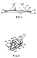
- This weakened section is provided during molding to provide a rectilinear thinner molded region 54 (see Figure 8) which extends midway between the two side edges 48.
- the cable 56 is first passed through the opening 42 before the insulated conductor wires are connected into terminals carried by the housing.
- These terminals 58 are of known construction and have insulation displacement portions 60 for lateral acceptance of conductors 62 of the cable while displacing the insulation locally from the conductor so as to make an electrical connection between the conductor and the insulation displacement portions.
- the terminals are disposed within the passageways 12 with the insulation displacement portions in the open parts of the passageways to provide accessability for the conductors to be assembled into the terminals.
- each terminal includes a strain relief means 64 of known construction and which comprises two tabs which are folded around the insulation of the respective conductor to transmit tensile load between the insulation and the terminal.
- the other end of each terminal (not shown) is housed within the closed part of its respective passageway and is a pin receptacle of conventional construction for electrical connection to a pin in a baseboard or at a connecting plane of some electrical apparatus with which the connector is to be used.
- the pin receptacle may be of a structure described in U.S. Patent 4,076,369 granted February 28, 1978 in the name of H.J. Ostopovitch.
- one of the cover portions 30 is first located in position upon its respective side of the housing. In this position, as shown in Figure 11, the one cover portion is located so as to lie across the open-sided parts of one bank of channels with its projections 38 extending into the closed-sided parts of its passageways and with the apertures 40 receiving the wall extensions 26 on that side of the housing. A slight flexing movement of the cover will assemble the cover portion into this position by firstly locating the projections 38 into the closed-sided parts of the passageways and then urging the apertures over the extensions 26.
- the spine portion 36 of the cover extends around the remote end of the housing with the cable passing through the opening 42 and the other cover portion lies loosely on the other side of the housing as shown by Figure 11.
- the spine portion is hingedly moved upon the cover portion which is already assembled into position so that it is hinged away from the remote end of the housing, as shown in Figure 11, thereby drawing the other and unassembled cover portion rearwardly of the housing to position the projections 38 of that cover portion over the open-sided parts of the other bank of passageways.
- the unassembled cover portion is then flexed as shown in Figure 12 to position the projections 38 through the open sides of the respective bank of channels.
- the cover described above provides a particularly rigid mounting which is easily assembled onto its housing and yet is resistant to conscious removal thereby rendering inadvertent removal substantially impossible.
- the cover construction will frustrate any manual attempt to remove it without the assistance of some appropriate tool.
- One simple and quick method of removing the cover is to insert a thin blade under one of the cover portions 30 from a side edge 48 to one side or the other of the extensions 26. The thin blade must then be urged along the tops of the walls between one side of the cover and the housing and a slight twisting action to the blade will effectively raise the apertured part of that cover portion away from the extensions 26 thereby allowing for removal of that cover portion from the housing.
- the other cover portion is then easily removed by urging the spine portion of the cover laterally of the connector housing, i.e. downwardly in Figure 13. This action moves the apertures 40 of the other cover portion from their extensions 26 permitting total removal of the cover.
- the weakened section 54 may be cut with a cutting edge so as to form a slit which separates the one cover portion into two parts. These parts may be flexed apart (as shown in chain-dotted outline in Figure 8) so as to widen the slit thereby enabling the cable to pass through the widened slit from the opening 42 thus allowing the cover to be removed.
- the same or a similar cover with the weakened section cut to form a slit may be refitted onto the housing and around the cable by following the reverse procedure. Thus the cable does not require to be disconnected and reconnected to the housing during the complete removal and replacement of covers.
- a cover according to the first embodiment has only a single component as distinct from two smaller components used in the prior art constructions. It will be appreciated that such smaller components are more difficult to handle manually and operation of their small latches requires a particular manual dexterity.
- the cover of the first embodiment may be made by a simple molding operation. Further, the use of the paddle 44 does not significantly increase the difficulty or complexity of molding a single one-piece cover which provides for flexible movement of the cover portions while the paddle remains in its required position of orientation.
- an integral one-piece cover 70 is of similar construction to that described in the first embodiment except that instead of having a weakened section as in the first emtodiment, the cover 70 is molded with a slit 72 extending across one cover portion between the opening 42 and its free edge 32 so that this particular cover portion is in fact molded into two parts separated by the slit. As shown in chain-dotted outline in Figure 15, the two parts of the cover portion may be flexed to widen the slit and accept a cable into opening 42.
- the cover 70 may be assembled onto the housing after the cable is connected to the housing. Its method of assembly is substantially the same as that described above with regard to a replacement cover in the first embodiment.
- the position of the slit 72 is such that the two parts of the cover portion bordering the slit oppose each other along the top of one of the walls 18 of the housing.
- a cover for a connector housing is of similar construction to that described in the first embodiment except that the cover of the third embodiment is not provided with an opening 42 for acceptance of cable.
- the cover 74 is formed with its flanges 50 and 52 at one side edge 48 of the cover removed or substantially removed to form an opening for passage of the cable 56 laterally of the connector.
- the opening faces in a direction parallel to the hinged edges of the cover portions with the cable projecting laterally.
Landscapes
- Connector Housings Or Holding Contact Members (AREA)
- Connecting Device With Holders (AREA)
- Manufacturing Of Electrical Connectors (AREA)
Applications Claiming Priority (2)
| Application Number | Priority Date | Filing Date | Title |
|---|---|---|---|
| CA548940 | 1987-10-08 | ||
| CA000548940A CA1277739C (en) | 1987-10-08 | 1987-10-08 | Electrical connectors |
Publications (2)
| Publication Number | Publication Date |
|---|---|
| EP0311249A2 true EP0311249A2 (de) | 1989-04-12 |
| EP0311249A3 EP0311249A3 (de) | 1990-07-18 |
Family
ID=4136621
Family Applications (1)
| Application Number | Title | Priority Date | Filing Date |
|---|---|---|---|
| EP88308039A Withdrawn EP0311249A3 (de) | 1987-10-08 | 1988-08-31 | Elektrische Steckverbinder |
Country Status (3)
| Country | Link |
|---|---|
| EP (1) | EP0311249A3 (de) |
| JP (1) | JPH01128382A (de) |
| CA (1) | CA1277739C (de) |
Cited By (2)
| Publication number | Priority date | Publication date | Assignee | Title |
|---|---|---|---|---|
| EP0392108A3 (de) * | 1989-04-14 | 1991-04-24 | The Whitaker Corporation | Gehäuse in Kombination mit einem Verbinder eines flachen Starkstromkabels |
| EP0920086A3 (de) * | 1997-11-25 | 2001-03-28 | Mecanismos Auxiliares Industriales S.A. M.A.I.S.A. | Verbesserte Kabelschuzführung |
Family Cites Families (5)
| Publication number | Priority date | Publication date | Assignee | Title |
|---|---|---|---|---|
| JPS5431674Y2 (de) * | 1974-03-04 | 1979-10-03 | ||
| GB1497560A (en) * | 1975-09-11 | 1978-01-12 | Amp Inc | Electrical connector assemblies |
| US4076369A (en) * | 1976-07-26 | 1978-02-28 | Northern Telecom Limited | Box terminal for card edge receptacles in telecommunications systems and the like |
| US4243288A (en) * | 1979-06-28 | 1981-01-06 | Amp Incorporated | Connector assembly for mass termination |
| FR2498821A1 (fr) * | 1981-01-23 | 1982-07-30 | Legrand Sa | Connecteur electrique pour conducteur isole |
-
1987
- 1987-10-08 CA CA000548940A patent/CA1277739C/en not_active Expired - Lifetime
-
1988
- 1988-08-31 EP EP88308039A patent/EP0311249A3/de not_active Withdrawn
- 1988-09-28 JP JP24116988A patent/JPH01128382A/ja active Pending
Cited By (2)
| Publication number | Priority date | Publication date | Assignee | Title |
|---|---|---|---|---|
| EP0392108A3 (de) * | 1989-04-14 | 1991-04-24 | The Whitaker Corporation | Gehäuse in Kombination mit einem Verbinder eines flachen Starkstromkabels |
| EP0920086A3 (de) * | 1997-11-25 | 2001-03-28 | Mecanismos Auxiliares Industriales S.A. M.A.I.S.A. | Verbesserte Kabelschuzführung |
Also Published As
| Publication number | Publication date |
|---|---|
| CA1277739C (en) | 1990-12-11 |
| EP0311249A3 (de) | 1990-07-18 |
| JPH01128382A (ja) | 1989-05-22 |
Similar Documents
| Publication | Publication Date | Title |
|---|---|---|
| US4449767A (en) | Connector assembly having improved keying and latching system | |
| US3920306A (en) | Tap connections for multi-conductor cables | |
| EP0570181B1 (de) | Elektrischer Verbinder für Hochfrequenz | |
| RU2137271C1 (ru) | Присоединительный элемент | |
| US4379605A (en) | Electrical receptacle of molded body construction | |
| RU2133071C1 (ru) | Усовершенствованная система перекрестного соединения для телекоммуникационных систем | |
| JP3195348B2 (ja) | 遠距離通信システム用改良交差接続システム | |
| JPH0635375Y2 (ja) | 側面入線電線コネクタ | |
| AU778341B2 (en) | A termination device e.g. for a multiconnector | |
| HU218129B (hu) | Sorozatkapocs | |
| JP2567857B2 (ja) | ケ−ブルワイヤ用のコネクタバンク | |
| US5406449A (en) | Pullout type electric disconnect switch | |
| US7632133B2 (en) | Cross connect terminal block | |
| KR920022594A (ko) | 멀티 컨닥터 전기 커넥터 | |
| US5224881A (en) | Connection strip having semi-integrated protectors | |
| US5076802A (en) | Wire dress cover | |
| US4274696A (en) | Electrical connecting device for wiring systems | |
| EP0608792B1 (de) | Wiederpositionierbarer Endmodul | |
| US4593960A (en) | Power entry connector | |
| GB2034538A (en) | A terminal block | |
| WO1993013580A1 (en) | Connection and branching sleeve for telecommunications cables, coaxial cables or glass fibre cables | |
| US6062895A (en) | Patch plug with contact blades | |
| US5971792A (en) | Patch plug | |
| JP3446974B2 (ja) | 電気コネクタ | |
| US5846101A (en) | Connection block for connecting electrical conductors to electrical equipment |
Legal Events
| Date | Code | Title | Description |
|---|---|---|---|
| PUAI | Public reference made under article 153(3) epc to a published international application that has entered the european phase |
Free format text: ORIGINAL CODE: 0009012 |
|
| AK | Designated contracting states |
Kind code of ref document: A2 Designated state(s): DE FR GB NL |
|
| PUAL | Search report despatched |
Free format text: ORIGINAL CODE: 0009013 |
|
| AK | Designated contracting states |
Kind code of ref document: A3 Designated state(s): DE FR GB NL |
|
| 17P | Request for examination filed |
Effective date: 19900831 |
|
| STAA | Information on the status of an ep patent application or granted ep patent |
Free format text: STATUS: THE APPLICATION HAS BEEN WITHDRAWN |
|
| 18W | Application withdrawn |
Withdrawal date: 19910618 |