EP0311261B1 - Halter zur Probenahme von geschmolzenem Metall - Google Patents
Halter zur Probenahme von geschmolzenem Metall Download PDFInfo
- Publication number
- EP0311261B1 EP0311261B1 EP88308369A EP88308369A EP0311261B1 EP 0311261 B1 EP0311261 B1 EP 0311261B1 EP 88308369 A EP88308369 A EP 88308369A EP 88308369 A EP88308369 A EP 88308369A EP 0311261 B1 EP0311261 B1 EP 0311261B1
- Authority
- EP
- European Patent Office
- Prior art keywords
- pipe
- closure element
- wire
- molten metal
- opening
- Prior art date
- Legal status (The legal status is an assumption and is not a legal conclusion. Google has not performed a legal analysis and makes no representation as to the accuracy of the status listed.)
- Expired - Lifetime
Links
- 229910052751 metal Inorganic materials 0.000 title claims abstract description 52
- 239000002184 metal Substances 0.000 title claims abstract description 52
- 238000005070 sampling Methods 0.000 title claims abstract description 27
- 239000000203 mixture Substances 0.000 claims abstract description 4
- 239000000463 material Substances 0.000 claims description 22
- 239000002893 slag Substances 0.000 claims description 10
- -1 salt compound Chemical class 0.000 claims description 4
- 235000008733 Citrus aurantifolia Nutrition 0.000 claims description 2
- 235000011941 Tilia x europaea Nutrition 0.000 claims description 2
- 150000001875 compounds Chemical class 0.000 claims description 2
- 239000004571 lime Substances 0.000 claims description 2
- 239000000523 sample Substances 0.000 description 13
- 238000007654 immersion Methods 0.000 description 7
- 239000000155 melt Substances 0.000 description 5
- 239000000919 ceramic Substances 0.000 description 4
- 238000011109 contamination Methods 0.000 description 4
- 230000001681 protective effect Effects 0.000 description 4
- 229910052782 aluminium Inorganic materials 0.000 description 3
- 238000007865 diluting Methods 0.000 description 3
- 238000002844 melting Methods 0.000 description 3
- 230000008018 melting Effects 0.000 description 3
- 239000012768 molten material Substances 0.000 description 3
- 239000011819 refractory material Substances 0.000 description 3
- 239000007787 solid Substances 0.000 description 3
- 239000000126 substance Substances 0.000 description 3
- VTYYLEPIZMXCLO-UHFFFAOYSA-L Calcium carbonate Chemical compound [Ca+2].[O-]C([O-])=O VTYYLEPIZMXCLO-UHFFFAOYSA-L 0.000 description 2
- CWYNVVGOOAEACU-UHFFFAOYSA-N Fe2+ Chemical compound [Fe+2] CWYNVVGOOAEACU-UHFFFAOYSA-N 0.000 description 2
- VYPSYNLAJGMNEJ-UHFFFAOYSA-N Silicium dioxide Chemical compound O=[Si]=O VYPSYNLAJGMNEJ-UHFFFAOYSA-N 0.000 description 2
- GWEVSGVZZGPLCZ-UHFFFAOYSA-N Titan oxide Chemical compound O=[Ti]=O GWEVSGVZZGPLCZ-UHFFFAOYSA-N 0.000 description 2
- 239000000853 adhesive Substances 0.000 description 2
- 230000001070 adhesive effect Effects 0.000 description 2
- XAGFODPZIPBFFR-UHFFFAOYSA-N aluminium Chemical compound [Al] XAGFODPZIPBFFR-UHFFFAOYSA-N 0.000 description 2
- 238000009835 boiling Methods 0.000 description 2
- 239000002131 composite material Substances 0.000 description 2
- 239000012895 dilution Substances 0.000 description 2
- 238000010790 dilution Methods 0.000 description 2
- 230000000694 effects Effects 0.000 description 2
- 229910001092 metal group alloy Inorganic materials 0.000 description 2
- 239000012266 salt solution Substances 0.000 description 2
- 229910052719 titanium Inorganic materials 0.000 description 2
- 239000010936 titanium Substances 0.000 description 2
- 229910052726 zirconium Inorganic materials 0.000 description 2
- 229910000831 Steel Inorganic materials 0.000 description 1
- RTAQQCXQSZGOHL-UHFFFAOYSA-N Titanium Chemical compound [Ti] RTAQQCXQSZGOHL-UHFFFAOYSA-N 0.000 description 1
- QCWXUUIWCKQGHC-UHFFFAOYSA-N Zirconium Chemical compound [Zr] QCWXUUIWCKQGHC-UHFFFAOYSA-N 0.000 description 1
- 239000003513 alkali Substances 0.000 description 1
- PNEYBMLMFCGWSK-UHFFFAOYSA-N aluminium oxide Inorganic materials [O-2].[O-2].[O-2].[Al+3].[Al+3] PNEYBMLMFCGWSK-UHFFFAOYSA-N 0.000 description 1
- 238000013459 approach Methods 0.000 description 1
- 230000004888 barrier function Effects 0.000 description 1
- 229910000019 calcium carbonate Inorganic materials 0.000 description 1
- 239000002775 capsule Substances 0.000 description 1
- 229910010293 ceramic material Inorganic materials 0.000 description 1
- 239000011248 coating agent Substances 0.000 description 1
- 238000000576 coating method Methods 0.000 description 1
- 229910052681 coesite Inorganic materials 0.000 description 1
- 238000004891 communication Methods 0.000 description 1
- 238000010276 construction Methods 0.000 description 1
- 239000000356 contaminant Substances 0.000 description 1
- 229910052593 corundum Inorganic materials 0.000 description 1
- 229910052906 cristobalite Inorganic materials 0.000 description 1
- 230000003111 delayed effect Effects 0.000 description 1
- 239000011521 glass Substances 0.000 description 1
- 231100001261 hazardous Toxicity 0.000 description 1
- 239000011796 hollow space material Substances 0.000 description 1
- JEIPFZHSYJVQDO-UHFFFAOYSA-N iron(III) oxide Inorganic materials O=[Fe]O[Fe]=O JEIPFZHSYJVQDO-UHFFFAOYSA-N 0.000 description 1
- 239000002655 kraft paper Substances 0.000 description 1
- 229910001338 liquidmetal Inorganic materials 0.000 description 1
- 150000002739 metals Chemical class 0.000 description 1
- 238000000034 method Methods 0.000 description 1
- 238000002156 mixing Methods 0.000 description 1
- 238000012856 packing Methods 0.000 description 1
- 230000002265 prevention Effects 0.000 description 1
- 150000003839 salts Chemical class 0.000 description 1
- 239000000565 sealant Substances 0.000 description 1
- 239000000377 silicon dioxide Substances 0.000 description 1
- 235000012239 silicon dioxide Nutrition 0.000 description 1
- 239000010959 steel Substances 0.000 description 1
- 229910052682 stishovite Inorganic materials 0.000 description 1
- 238000012360 testing method Methods 0.000 description 1
- 229910052905 tridymite Inorganic materials 0.000 description 1
- 238000005303 weighing Methods 0.000 description 1
- 239000002023 wood Substances 0.000 description 1
- 229910001845 yogo sapphire Inorganic materials 0.000 description 1
Images


Classifications
-
- G—PHYSICS
- G01—MEASURING; TESTING
- G01N—INVESTIGATING OR ANALYSING MATERIALS BY DETERMINING THEIR CHEMICAL OR PHYSICAL PROPERTIES
- G01N1/00—Sampling; Preparing specimens for investigation
- G01N1/02—Devices for withdrawing samples
- G01N1/10—Devices for withdrawing samples in the liquid or fluent state
- G01N1/12—Dippers; Dredgers
- G01N1/125—Dippers; Dredgers adapted for sampling molten metals
-
- C—CHEMISTRY; METALLURGY
- C21—METALLURGY OF IRON
- C21C—PROCESSING OF PIG-IRON, e.g. REFINING, MANUFACTURE OF WROUGHT-IRON OR STEEL; TREATMENT IN MOLTEN STATE OF FERROUS ALLOYS
- C21C5/00—Manufacture of carbon-steel, e.g. plain mild steel, medium carbon steel or cast steel or stainless steel
- C21C5/28—Manufacture of steel in the converter
- C21C5/42—Constructional features of converters
- C21C5/46—Details or accessories
- C21C5/4673—Measuring and sampling devices
-
- Y—GENERAL TAGGING OF NEW TECHNOLOGICAL DEVELOPMENTS; GENERAL TAGGING OF CROSS-SECTIONAL TECHNOLOGIES SPANNING OVER SEVERAL SECTIONS OF THE IPC; TECHNICAL SUBJECTS COVERED BY FORMER USPC CROSS-REFERENCE ART COLLECTIONS [XRACs] AND DIGESTS
- Y10—TECHNICAL SUBJECTS COVERED BY FORMER USPC
- Y10S—TECHNICAL SUBJECTS COVERED BY FORMER USPC CROSS-REFERENCE ART COLLECTIONS [XRACs] AND DIGESTS
- Y10S73/00—Measuring and testing
- Y10S73/09—Molten metal samplers
Definitions
- the present invention relates to molten metal sampling devices, especially to such devices with a non-diluting and non-contaminating protection cap and entrance system.
- Prior samplers have been designed with a capping and entrance system that melted along with and into the molten material being sampled. This caused a source of undesirable contaminants to flow into the actual sample chamber.
- the prior method also allowed elements contained in the capping system to cause a diluting effect on similar elements contained in the molten batch material.
- the location being sampled may contain extremely low (typically, 10 to 50 ppm) values of certain elements, for example, C, S, Mn, O2, H and N, that must be accurately analyzed in order to produce a high quality product. At these minute ranges, any outside contamination or dilution can cause a significant error in accurate analysis.
- FR-A-1526144 One form of rapid sampling device devised with the aim of minimised contamination of samples is described in FR-A-1526144. This includes a narrow entrance for molten metal and a plug held in a conical opening by a retaining element and which floats away on melting of the retaining element.
- the non-diluting/non-contaminating quick release feature of the present invention has the following advantages over known prior art:
- this invention provides a holder for a molten metal sampling device comprising an entrance system, a closure element therefor having a density such that it will seek to flow upwardly in molten metal being sampled and a retaining element holding the closure element against the opening to close the same, the retaining element having a configuration, location and composition such that it will readily melt upon contact with the molten metal,
- the entrance system comprises a pipe which is elongated in a given direction, the pipe having an upper portion and a lower portion, the lower portion defining an internal guidance chamber and having an opening in a direction oblique to said given direction, the opening communicating with the guidance chamber, the upper portion being adapted to receive and retain the molten metal sampling device in such a way that molten metal in the guidance chamber can be sampled by the sampling device.
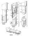
- the sampling device shown has three essential components 1, 2 and 3.
- Component 1 is a guidance chamber tube
- component 2 is a quick-release cap
- component 3 is a protective sleeve.
- 13 represents the protective sleeve, which is preferably covered with a low thermoconductivity, non-boiling coating 26, as seen in Figure 2.
- a thick-walled pipe 11 Inserted within the lower end of the sleeve 13 is a thick-walled pipe 11 which has a square cut opening 27 at the top end, and a diagonally cut opening 16 at the bottom.
- the opening 16 lies in a plane which defines an angle of 45° with the axis of the pipe 11.
- the pipe 11 may be of metal, metal alloy, refractory or ceramic material.
- a molten metal sampling device 9 Contained in the upper portion of the pipe 11 is a molten metal sampling device 9 which is of conventional nature, consisting of two identical mold halves 21 which fit together to define a lollypop-like cavity which will receive the metal sample.
- a filling pin 20 typically made of high-temperature glass and being open at the bottom end 20a.
- the filling pin extends downwardly through a central opening in a retainer cup 22.
- the retainer cup 22 could be replaced by a heavy washer that will not melt on contact with the molten metal.
- the sampling device 9 is held in place by the provision of a high-temperature packing material 23, in known manner.
- a strip of the deoxidizing material 19 Trapped between the retainer cup 22 and the inside wall of the pipe 11 is a strip of the deoxidizing material 19 which may typically be aluminum, zirconium, or titanium.
- a closure element is shown generally at 8. It has a substantially cylindrical portion 12 which is shaped as if it were a continuation of the pipe 11. To this end, the closure element 8 has an oblique upper surface 24, making the same angle with the axis of the portion 12 as is made by the opening 16 with respect to the axis of the pipe 11.
- the closure element 8 may have a hollow interior 25 in order to reduce its weight and increase floatation.
- the pipe 11 has mounted therein a detent 15a in the form of an eyelet.
- a fusible wire 14, seen in Figure 1 extends through the opening 15 and through the detent 15a, in order to urge the closure element 8 against the opening 16 at the bottom of the pipe 11.
- a further component of the closure means is provided by a pin or projection 17, located in such a way that it can lie within and against the pipe 11 at the uppermost location on the perimeter of the opening 16. This prevents the closure element from sliding obliquely upwardly and rightwardly (as pictured in Figure 2), thus failing to close the opening 16.
- the fusible wire 14 is made of a metal with a low melting point by comparison with the molten metal to be sampled.
- a high temperature sealant 24 is provided at the bottom of the protection sleeve 13.
- the closure element 8 is secured to the bottom of the pipe 11, by lodging the projection 17 inside the uppermost point of the opening 16, and running the wire 14 between the opening 15 and the detent 15a and securely fastening it.
- the operator using the protection sleeve 13 plunges the pipe 11 and the closure element 8 through the slag layer covering the molten metal in a suitable vessel, the heat of the melt quickly fuses the wire 14, which allows the closure element to rotate in counterclockwise motion about the projection 17 where it is "caught" within the upper portion of the opening 16. This opens the opening 16 to allow molten metal to enter the filling pin 20.
- the closure element 8 rapidly floats to the top surface of the melt.
- the closure element Because of the material from which the closure element is made, preferably ceramic or refractory material, it does not melt into and contaminate the metal from which a sample is being taken.
- the position of the wire 14 is such that it will not contaminate the molten metal flowing into the opening 16.
- the operator may extend the sampling device downwardly at an angle (downwardly and to the right for the configurations shown in Figures 1 and 2), which will enhance the floatation of the closure element 8.
- an angle downwardly and to the right for the configurations shown in Figures 1 and 2
- the sampling device described herein functions satisfactorily at any angle.
- the relatively thick-walled pipe 11 will constitute a heat sink for any materials which contact it, particularly if it is made of metal or metal alloy.
- the wire 14 were to lie against the pipe 11 at all locations, the melting of the wire 14 by heat of the liquid metal would be delayed and possibly prevented. It is considered important to this invention that at least a portion of the wire 14 be held away from contact with any other parts of the combination which could constitute a heat sink.
- the wire 14 is spaced away from the pipe 11, and only lies against the flange 28 of the closure element 8. Because the closure element 8 is not made of metal, this contact with the flange 28 will not seriously interfere with the fusing of the wire 14.
- all exposed parts of the sampler including the wire 14, may be coated with a slag retardant, or a gas-evolving substance such as a salt solution or calcium carbonate.
- a slag retardant or a gas-evolving substance such as a salt solution or calcium carbonate.
- a salt solution it has been found that contact between the salt and the molten metal creates gas which acts as a barrier preventing the slag from contacting the sampler.
- the primary difference exhibited by the second embodiment lies in the configuration of the closure element 8a.
- the closure element 8a has a groove 35 in line with the highest point on the surface 24, and has fuse-release standoffs 38 on opposite sides.
- Figures 5 and 8 show the way in which a fusible wire 14a wraps around both the closure element 8a and the pipe 11, by passing over the standoffs 38.
- the pipe 11 has affixed thereto a flange 15b around which the wire 14a can be secured.
- the flange 15b has a J-shape to facilitate snagging the wire 14a.
- a hinging-rotation of the closure element 8a can be effected as soon as the wire 14a melts.
- this rotation and removal of the closure element 8a is enhanced if the operator plunges the lower end of the sampling device into the melt on an angle which would be downwardly and to the right as viewed in Figure 6.
- the closure element 8a may be solid or hollow, depending upon the degree of floatation required.
- Figure 9 shows a further embodiment, differing from that of Figure 1 only in the addition of a further flange 40 with an opening 41, along with a further detent 42 in the shape of an eyelet.
- a further wire 14b is provided, and is tightened through the eyelet 42 and the opening 41.
- FIG. 10 involves the use of a closure element 8c which is bent to the right as seen in the figure, so that floatation will be enhanced.
- a flange 28a projects outwardly to the left and has an opening 15c.
- a bracket 15a on the pipe 11 has an opening through which a wire 14c passes. Again, the mode of operation is the same as described for the other embodiments.
- Figures 11, 12 and 13 illustrate a further embodiment, in which a pipe 61 again defines a guidance chamber in its upper portion. Its lower end is open obliquely as at 16, similarly to the configuration of Figure 1.
- the closure element 8d consists of a first flat portion 62, and a further flat portion 67 extending downwardly at an angle of 45° with respect to the portion 62.
- a flange 65 is secured to the pipe 61, identically to the flange 15b in Figure 5.
- the fusible wire 64 is adapted to wrap under the portion 62 and to be snagged in the brackets 65, thus holding the closure element 8d in position until the wire 64 melts due to the heat of the molten metal.
- the closure element 8d could be made from a relatively dense material (such as steel), in which case it would be advisable to secure either to the portion 62 or to the portion 62 a block of low-density buoyant material such as wood or light refractory.
- Figures 15 and 16 show the final embodiment of this invention.
- the pipe 90 is cut on an angle as shown at 92 in Figure 26.
- a solid closure member 94 which may be of ceramic or refractory material, also has a diagonal cut at the top so that it can be received against the angled bottom 92 of the pipe 90.
- a metallic band 96 is secured by adhesive or other suitable means to the pipe 90, as shown at 98, and has a bottom portion 100 which penetrates into and is buried within the closure member 94.
- the element 96 includes a portion 102 which is spaced away from the pipe 90, thus allowing the molten metal to dissolve the element 96, thus releasing the closure member 94 so that it can separate from the pipe 90 and allow molten metal to enter the interior of the pipe 90.
- the present invention provides a novel form of metal sampling device having a protective cap which does not contaminate the metal sample during sampling.
Landscapes
- Chemical & Material Sciences (AREA)
- Engineering & Computer Science (AREA)
- Life Sciences & Earth Sciences (AREA)
- General Physics & Mathematics (AREA)
- Pathology (AREA)
- Analytical Chemistry (AREA)
- Biochemistry (AREA)
- General Health & Medical Sciences (AREA)
- Physics & Mathematics (AREA)
- Immunology (AREA)
- Health & Medical Sciences (AREA)
- Hydrology & Water Resources (AREA)
- Manufacturing & Machinery (AREA)
- Materials Engineering (AREA)
- Metallurgy (AREA)
- Organic Chemistry (AREA)
- Sampling And Sample Adjustment (AREA)
- Investigating And Analyzing Materials By Characteristic Methods (AREA)
Claims (9)
- Halter für einen Probennehmer (9) von geschmolzenem Metall mit einer Einlaßeinrichtung, einem Verschlußelement (8; 14) dafür, das eine solche Dichte aufweist, daß es in einem geschmolzenen zur Probenahme vorgesehenen Metall aufzuschwimmen streben wird, und einem das Verschlußelement gegen die Öffnung, um sie zu schließen, haltenden Halteelement (14; 64; 96), wobei das Halteelement eine Gestalt, Lage und Aufbau aufweist, derart, daß es schnell bei Kontakt mit geschmolzenem Metall schmilzt, dadurch gekennzeichnet, daß die Einlaßrichtung ein Rohr (11; 61; 90) enthält, das in einer vorgegebenen Richtung verlängert ist und das Rohr ein Oberteil und ein Unterteil aufweist, wobei das Unterteil eine innere Führungskammer begrenzt und eine Öffnung (16) in schräger Richtung zu der vorgegebenen Richtung aufweist und die Öffnung mit der Führungskammer in Verbindung steht und das Oberteil zum Aufnehmen und Halten des Probennehmers (9) für das geschmolzene Metall in der Weise ausgebildet ist, daß Proben von geschmolzenem Metall in der Führungskammer von dem Probennehmer entnommen werden können.
- Erfindung gemäß Anspruch 1,
bei der das Halteelement ein Metalldraht (14a,64) ist, der um beide, das Rohr (11, 61) und das Verschlußelement (8a, 62), gelegt ist, die Lage des Drahtes dabei derart ist, daß zumindest ein Teil desselben von beiden, dem Rohr und dem Verschlußelement, beabstandet ist, wobei ein Teil vorgesehen wird, daß schnell ohne eine infolge der Nähe eines Wärmeableiters oder Kontaktes hervorgerufene Verzögerung schnell abschmelzen kann. - Erfindung gemäß Anspruch 1,
bei der das Verschlußelement (8a) einen Vorsprung (17) aufweist, der so ausgebildet ist, daß er innerhalb des Rohres an der höchsten Stelle der Peripherie der Öffnung angeordnet ist und bei der das Halteelement ein Metalldraht (14a) ist, der derart angeschlossen ist, um das Verschlußelement aufwärts in bezug auf das Rohr zu treiben. - Erfindung gemäß Anspruch 3,
bei der das Verschlußelement (8a) eine äußere Kerbe (35) und das Rohr (11) einen Anschlag (15b) aufweist, und der Draht (14a) die Verbindungsstelle zwischen Rohr und Verschlußelement übergreift, wobei der Draht innerhalb der Kerbe liegt und in Kontakt mit dem Anschlag steht und das Verschlußelement zumindest einen äußeren Vorsprung (38) aufweist, über den der Draht geführt ist, wobei ein Teil des Drahtes von dem Kontakt mit entweder dem Verschlußelement oder dem Rohr abgehoben ist. - Erfindung gemäß Anspruch 3,
bei der beide, das Verschlußelement (8) und das Rohr (11), Anschläge (15, 15a) aufweisen, zwischen denen der Draht (14) anschließbar ist, um das Verschlußelement in eine dichte Verbindung mit dem Rohr zu ziehen, wobei die Anschläge derart sind, daß zumindest ein Teil des Drahtes von dem Kontakt mit entweder dem Verschlußelement oder dem Rohr entfernt ist, und der Draht diametral gegenüber dem höchsten Punkt der Öffnung angeordnet ist. - Erfindung gemäß einem der vorangehenden Ansprüche in Kombination mit einem Probennehmer für geschmolzenes Metall, wobei der letztere in dem oberen Teil des Rohres angebracht ist.
- Erfindung nach einem der vorangehenden Ansprüche,
bei der exponierte Teile des Halters mit einem Material beschichtet sind, das dem Streben der Schlacke zum Anhaften an dem Halter entgegenwirkt. - Erfindung gemäß Anspruch 7,
bei der das Material eine Salzkomponente ist. - Erfindung gemäß Anspruch 7,
bei der das Material eine Komponente auf Kalkbasis ist.
Priority Applications (1)
| Application Number | Priority Date | Filing Date | Title |
|---|---|---|---|
| AT88308369T ATE82635T1 (de) | 1987-09-09 | 1988-09-09 | Halter zur probenahme von geschmolzenem metall. |
Applications Claiming Priority (2)
| Application Number | Priority Date | Filing Date | Title |
|---|---|---|---|
| GB8721185 | 1987-09-09 | ||
| GB878721185A GB8721185D0 (en) | 1987-09-09 | 1987-09-09 | Molten metal sampling device |
Publications (3)
| Publication Number | Publication Date |
|---|---|
| EP0311261A2 EP0311261A2 (de) | 1989-04-12 |
| EP0311261A3 EP0311261A3 (en) | 1989-10-04 |
| EP0311261B1 true EP0311261B1 (de) | 1992-11-19 |
Family
ID=10623502
Family Applications (1)
| Application Number | Title | Priority Date | Filing Date |
|---|---|---|---|
| EP88308369A Expired - Lifetime EP0311261B1 (de) | 1987-09-09 | 1988-09-09 | Halter zur Probenahme von geschmolzenem Metall |
Country Status (6)
| Country | Link |
|---|---|
| US (1) | US4932271A (de) |
| EP (1) | EP0311261B1 (de) |
| AT (1) | ATE82635T1 (de) |
| CA (1) | CA1334343C (de) |
| DE (1) | DE3876064T2 (de) |
| GB (1) | GB8721185D0 (de) |
Families Citing this family (7)
| Publication number | Priority date | Publication date | Assignee | Title |
|---|---|---|---|---|
| CA2007179C (en) * | 1989-05-05 | 1995-02-07 | Gary H. Haughton | Holder for molten metal sampling device |
| JP4509403B2 (ja) * | 2000-02-18 | 2010-07-21 | ヘレーウス エレクトロ−ナイト インターナシヨナル エヌ ヴイ | 溶融物用試料採取装置 |
| DE10360625B3 (de) * | 2003-12-19 | 2005-01-13 | Heraeus Electro-Nite International N.V. | Probennehmer für Metallschmelzen |
| DE102008057797B4 (de) * | 2008-11-17 | 2013-11-28 | Heraeus Electro-Nite International N.V. | Vorrichtung zur Probennahme von Metallschmelzen |
| DE102010053710B4 (de) * | 2010-12-07 | 2012-12-27 | Heraeus Electro-Nite International N.V. | Verfahren und Vorrichtung zur Analyse von Proben von Metallschmelzen |
| KR101709135B1 (ko) * | 2015-11-02 | 2017-02-22 | 주식회사 포스코 | 용강 샘플링 장치 |
| CN113466322B (zh) * | 2021-06-17 | 2022-10-14 | 新疆众和股份有限公司 | 一种高纯铝熔炼用接触材质对铝液污染程度的检测方法 |
Family Cites Families (9)
| Publication number | Priority date | Publication date | Assignee | Title |
|---|---|---|---|---|
| US3452602A (en) * | 1966-06-27 | 1969-07-01 | Robert J Hackett | Metal sampling device |
| DE1598830C3 (de) * | 1967-03-20 | 1975-11-20 | Mannesmann Ag, 4000 Duesseldorf | Verfahren zur Bestimmung des Endkohlenstoffgehaltes einer Stahlschmelze sowie Meßlanze zur Durchfuhrung des Verfahrens |
| FR1526144A (fr) * | 1967-04-10 | 1968-05-24 | Siderurgie Fse Inst Rech | Dispositif de prélèvement rapide d'un échantillon dans un bain de métal liquide |
| GB1349774A (en) * | 1971-06-29 | 1974-04-10 | Falk R A | Sampling lances |
| US3877309A (en) * | 1974-03-25 | 1975-04-15 | Richard J Hance | Immersion sampler for molten material |
| US4067242A (en) * | 1974-11-19 | 1978-01-10 | National Steel Corporation | Molten metal sampling device and method |
| FR2421373A1 (fr) * | 1978-03-30 | 1979-10-26 | Electro Nite | Event-obturateur pour dispositif de prise d'echantillon de metal en fusion |
| US4250754A (en) * | 1979-05-09 | 1981-02-17 | Collins William J | Sampler for a hot liquid and connector therefor |
| DE3402818C2 (de) * | 1984-01-26 | 1986-07-03 | Gustav 5870 Hemer Kolb | Vorrichtung zur Entnahme von Tauchproben aus Eisenschmelzen |
-
1987
- 1987-09-09 GB GB878721185A patent/GB8721185D0/en active Pending
-
1988
- 1988-09-06 US US07/240,506 patent/US4932271A/en not_active Expired - Lifetime
- 1988-09-06 CA CA000576574A patent/CA1334343C/en not_active Expired - Fee Related
- 1988-09-09 AT AT88308369T patent/ATE82635T1/de not_active IP Right Cessation
- 1988-09-09 EP EP88308369A patent/EP0311261B1/de not_active Expired - Lifetime
- 1988-09-09 DE DE8888308369T patent/DE3876064T2/de not_active Expired - Fee Related
Also Published As
| Publication number | Publication date |
|---|---|
| US4932271A (en) | 1990-06-12 |
| CA1334343C (en) | 1995-02-14 |
| DE3876064T2 (de) | 1993-05-06 |
| DE3876064D1 (de) | 1992-12-24 |
| EP0311261A3 (en) | 1989-10-04 |
| ATE82635T1 (de) | 1992-12-15 |
| EP0311261A2 (de) | 1989-04-12 |
| GB8721185D0 (en) | 1987-10-14 |
Similar Documents
| Publication | Publication Date | Title |
|---|---|---|
| US4932271A (en) | Molten metal sampling device | |
| US3369406A (en) | Molten material sampling apparatus and method | |
| UA81824C2 (uk) | Спосіб і пристрій для вимірювання кривої охолодження розплавів | |
| US3315529A (en) | Method and apparatus for taking samples from melts in order to obtain the gases evolved during solidification | |
| OA10227A (en) | Sensor array for measuring temperatures | |
| JP6574225B2 (ja) | スラグ試料採取用浸漬装置 | |
| US4941364A (en) | Holder for molten metal sampling device | |
| KR100797859B1 (ko) | 용금 중의 입자상 물질의 검출 및 측정 장치 | |
| US3298069A (en) | Sampler | |
| US5187991A (en) | Device for withdrawing samples from molten metals | |
| US4428245A (en) | Apparatus for sampling molten metal | |
| SE437582B (sv) | Behallare for upptagande och forvaring av utbrenda brensleelement | |
| US3321978A (en) | Molten metal sampling apparatus | |
| US4002069A (en) | Measuring lance for molten metal such as steel | |
| US3704621A (en) | Sampling bomb and method of sampling and analyzing a heat of unkilled steel | |
| US4125024A (en) | Molten metal sampling device | |
| US5447080A (en) | Additive for molten metal sampler | |
| US5948350A (en) | Device for dispensing additive in molten metal sample mold | |
| EP0404291B1 (de) | Haltevorrichtung für einen Probenehmer für Metallschmelzen | |
| US5448923A (en) | Scored metal slag covers for molten sampler intake portals | |
| US4362562A (en) | Method for taking samples from pig-iron melts | |
| CZ21698A3 (cs) | Reakční kelímek pro aluminotermické zařízení na svařování kolejnic | |
| SU601595A1 (ru) | Устройство дл отбора проб шлакового расплава | |
| EP0178593A3 (de) | Vorrichtung zum geschützten und schlackenfreien Abgiessen einer Schmelze aus einem Gefäss in einen Giessofen | |
| US5223125A (en) | Oxygen sensor for aluminum killed, high silicon steel melts |
Legal Events
| Date | Code | Title | Description |
|---|---|---|---|
| PUAI | Public reference made under article 153(3) epc to a published international application that has entered the european phase |
Free format text: ORIGINAL CODE: 0009012 |
|
| AK | Designated contracting states |
Kind code of ref document: A2 Designated state(s): AT BE CH DE ES FR GB GR IT LI LU NL SE |
|
| PUAL | Search report despatched |
Free format text: ORIGINAL CODE: 0009013 |
|
| AK | Designated contracting states |
Kind code of ref document: A3 Designated state(s): AT BE CH DE ES FR GB GR IT LI LU NL SE |
|
| 17P | Request for examination filed |
Effective date: 19900404 |
|
| 17Q | First examination report despatched |
Effective date: 19910416 |
|
| GRAA | (expected) grant |
Free format text: ORIGINAL CODE: 0009210 |
|
| AK | Designated contracting states |
Kind code of ref document: B1 Designated state(s): AT BE CH DE ES FR GB GR IT LI LU NL SE |
|
| PG25 | Lapsed in a contracting state [announced via postgrant information from national office to epo] |
Ref country code: IT Free format text: LAPSE BECAUSE OF FAILURE TO SUBMIT A TRANSLATION OF THE DESCRIPTION OR TO PAY THE FEE WITHIN THE PRE;WARNING: LAPSES OF ITALIAN PATENTS WITH EFFECTIVE DATE BEFORE 2007 MAY HAVE OCCURRED AT ANY TIME BEFORE 2007. THE CORRECT EFFECTIVE DATE MAY BE DIFFERENT FROM THE ONE RECORDED.SCRIBED TIME-LIMIT Effective date: 19921119 Ref country code: GR Free format text: LAPSE BECAUSE OF FAILURE TO SUBMIT A TRANSLATION OF THE DESCRIPTION OR TO PAY THE FEE WITHIN THE PRESCRIBED TIME-LIMIT Effective date: 19921119 Ref country code: LI Effective date: 19921119 Ref country code: ES Free format text: THE PATENT HAS BEEN ANNULLED BY A DECISION OF A NATIONAL AUTHORITY Effective date: 19921119 Ref country code: NL Effective date: 19921119 Ref country code: AT Effective date: 19921119 Ref country code: CH Effective date: 19921119 |
|
| REF | Corresponds to: |
Ref document number: 82635 Country of ref document: AT Date of ref document: 19921215 Kind code of ref document: T |
|
| REF | Corresponds to: |
Ref document number: 3876064 Country of ref document: DE Date of ref document: 19921224 |
|
| ET | Fr: translation filed | ||
| REG | Reference to a national code |
Ref country code: CH Ref legal event code: PL |
|
| NLV1 | Nl: lapsed or annulled due to failure to fulfill the requirements of art. 29p and 29m of the patents act | ||
| PLBE | No opposition filed within time limit |
Free format text: ORIGINAL CODE: 0009261 |
|
| STAA | Information on the status of an ep patent application or granted ep patent |
Free format text: STATUS: NO OPPOSITION FILED WITHIN TIME LIMIT |
|
| 26N | No opposition filed | ||
| EPTA | Lu: last paid annual fee | ||
| EAL | Se: european patent in force in sweden |
Ref document number: 88308369.3 |
|
| REG | Reference to a national code |
Ref country code: GB Ref legal event code: IF02 |
|
| PGFP | Annual fee paid to national office [announced via postgrant information from national office to epo] |
Ref country code: GB Payment date: 20020830 Year of fee payment: 15 |
|
| PGFP | Annual fee paid to national office [announced via postgrant information from national office to epo] |
Ref country code: LU Payment date: 20020917 Year of fee payment: 15 |
|
| PGFP | Annual fee paid to national office [announced via postgrant information from national office to epo] |
Ref country code: FR Payment date: 20020918 Year of fee payment: 15 |
|
| PGFP | Annual fee paid to national office [announced via postgrant information from national office to epo] |
Ref country code: SE Payment date: 20020919 Year of fee payment: 15 |
|
| PGFP | Annual fee paid to national office [announced via postgrant information from national office to epo] |
Ref country code: DE Payment date: 20020930 Year of fee payment: 15 |
|
| PGFP | Annual fee paid to national office [announced via postgrant information from national office to epo] |
Ref country code: BE Payment date: 20021011 Year of fee payment: 15 |
|
| PG25 | Lapsed in a contracting state [announced via postgrant information from national office to epo] |
Ref country code: GB Free format text: LAPSE BECAUSE OF NON-PAYMENT OF DUE FEES Effective date: 20030909 Ref country code: LU Free format text: LAPSE BECAUSE OF NON-PAYMENT OF DUE FEES Effective date: 20030909 |
|
| PG25 | Lapsed in a contracting state [announced via postgrant information from national office to epo] |
Ref country code: SE Free format text: LAPSE BECAUSE OF NON-PAYMENT OF DUE FEES Effective date: 20030910 |
|
| PG25 | Lapsed in a contracting state [announced via postgrant information from national office to epo] |
Ref country code: BE Free format text: LAPSE BECAUSE OF NON-PAYMENT OF DUE FEES Effective date: 20030930 |
|
| BERE | Be: lapsed |
Owner name: *EVACUO ENTERPRISES LTD Effective date: 20030930 |
|
| PG25 | Lapsed in a contracting state [announced via postgrant information from national office to epo] |
Ref country code: DE Free format text: LAPSE BECAUSE OF NON-PAYMENT OF DUE FEES Effective date: 20040401 |
|
| GBPC | Gb: european patent ceased through non-payment of renewal fee |
Effective date: 20030909 |
|
| EUG | Se: european patent has lapsed | ||
| PG25 | Lapsed in a contracting state [announced via postgrant information from national office to epo] |
Ref country code: FR Free format text: LAPSE BECAUSE OF NON-PAYMENT OF DUE FEES Effective date: 20040528 |
|
| REG | Reference to a national code |
Ref country code: FR Ref legal event code: ST |