EP0311277B1 - Luftschraubenblattanlage - Google Patents
Luftschraubenblattanlage Download PDFInfo
- Publication number
- EP0311277B1 EP0311277B1 EP19880308804 EP88308804A EP0311277B1 EP 0311277 B1 EP0311277 B1 EP 0311277B1 EP 19880308804 EP19880308804 EP 19880308804 EP 88308804 A EP88308804 A EP 88308804A EP 0311277 B1 EP0311277 B1 EP 0311277B1
- Authority
- EP
- European Patent Office
- Prior art keywords
- valve
- port
- blade pitch
- pitch control
- control system
- Prior art date
- Legal status (The legal status is an assumption and is not a legal conclusion. Google has not performed a legal analysis and makes no representation as to the accuracy of the status listed.)
- Expired - Lifetime
Links
Images

Classifications
-
- B—PERFORMING OPERATIONS; TRANSPORTING
- B64—AIRCRAFT; AVIATION; COSMONAUTICS
- B64C—AEROPLANES; HELICOPTERS
- B64C11/00—Propellers, e.g. of ducted type; Features common to propellers and rotors for rotorcraft
- B64C11/30—Blade pitch-changing mechanisms
- B64C11/38—Blade pitch-changing mechanisms fluid, e.g. hydraulic
- B64C11/40—Blade pitch-changing mechanisms fluid, e.g. hydraulic automatic
Definitions
- This invention relates to propeller blade systems and, in particular, a blade pitch control system for use therewith.
- the present invention is concerned with reducing the weight and bulk of the system whilst providing, or substantially so, a similar degree of integrity, and thereby reliability.
- GB 2180892A discloses a blade pitch control system for use with a propeller system having one or more propellers including a constant speed valve and an overspeed valve and in which the operation of the constant speed valve, but not the overspeed valve, is controlled by computer means.
- a malfunction such as an engine failure
- the propeller blades being maintained at an undesirable pitch angle.
- US 3002 568 also discloses a multi-propeller blade pitch control system which comprises a constant speed valve and an overspeed valve. This control system operates automatically to set the blade pitch to a fully feathered position under engine failure conditions, so as to reduce drag to a minimum, the propeller blades not then rotating.
- the present invention provides an improved blade pitch control system characterised in that both the constant speed valve and overspeed valve are controlled by computer means, and the propeller blades are automatically set to a non-fully feathered, minimum drag position in which the propeller rotates in the airflow so as to provide minimum drag characteristics in the event of a malfunction.
- the overspeed valve may be a hydraulic mechanical valve i.e. a mechanical governor valve.
- the constant speed valve and the overspeed valve are preferably servo valves, and, most preferably, two stage servo valves.
- servo valves are preferably electrically operated two stage servo valves.
- the computer means may be an analogue computer system. However, preferably, the computer means is a digital means and most preferably a microprocessor.
- the propeller blade pitch control system further comprises a blade pitch control valve (beta valve).
- a blade pitch control valve beta valve
- Any suitable type of beta valve may be used with this invention, and the use of a particular beta valve shall not be construed as limiting the scope of the invention.
- the system may be set to feather and unfeather by means of the constant speed valve.
- a blade pitch control system comprises:
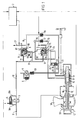
- the beta valve assembly 1 which controls the pitch of propellers 1A having counterweights 1B comprises:
- the first passageways 1D and 1G co-operate to connect fluid to the assembly in such a way as to drive the pitch fine and the second passageways 1E and 1H co-operate to connect fluid to the assembly so as to drive the pitch coarse.
- Both of the servo valves 7, 8 have a first stage A, and a second stage B which includes a spool member B1, and four ports 7A - 7D and 8A - 8D respectively.
- the high pressure gear pump 3 has a fluid feed line 9 and a fluid outlet line 10.
- a pressure relief valve 4 is bridged, by means of lines 9A and 10A, across the gear pump to vent the system in cases of excessive pressure build up in the system.
- the line 10 is connected to the first stages of both servo valves 7, 8 by means of branch lines 11, 12 respectively. Further, a branch line 13 connects to the port 8B of the overspeed two stage servo valve 8 to provide the blade pitch control system with a supply of high pressure fluid necessary to operate the beta valve assembly 1.
- the port 8A of the overspeed servo valve 8 is connected to the port 7B and the port 7A of the constant speed servo valve 7 and thereby the fine side of the beta valve assembly 1 by means of line 14 which divides into lines 15 and 16.
- the line 15 connects the overspeed servo valve 8 port 8A to the constant speed servo valve 7 port 7B and, the line 16 connects the port 8A of the overspeed servo valve 8 to port 7A of the constant speed servo valve 7 and to the fine side of the beta valve assembly 1.
- a non return valve 17 is provided in the line 16 between the line 14 and the port 7A of the constant speed servo-valve 7 to prevent fluid flow from the line 14 to the port 7A and the fine side of the beta valve assembly 1.
- the port 8C of the overspeed servo valve is a dummy port.
- the port 8D of the overspeed servo valve 8 has a line 18 connected thereto which is connected to the output side of the second gear pump 5.
- the second gear pump is fed from a reserve tank (not shown).
- the pressure relief valve 6 is bridged across the pump 5 to prevent excessive pressure building up in the output side line of the pump 5 prior to the non return valve 20. Further, the line 18 is provided with two non return valves 19 and 20, and is branched at a point between the two non return valves 19, 20 by a line 21 which connects to a port 22 of a shuttle valve 23.
- the non return valve 19 prevents fluid flowing to port 8D from the gear pump 5, or the shuttle valve 23, whilst the non return valve 20 prevents fluid flow from port 8D or the shuttle valve 23 to the gear pump 5.
- the line 18 is provided with a restricted drain line 27.
- the port 7C of the constant speed servo valve 7 is connected by a line 24 to a port 25 of the shuttle valve 23, whilst a line 28 interconnects the coarse side of the beta valve assembly 1 to a port 26 of the shuttle valve 23.
- Port 7D of the constant speed servo valve is connected to drain.
- the shuttle valve 23 is biased by mechanical means so that in normal operation the port 25 is in communication with the port 26 and the port 22 is closed.
- the microprocessor 2 (the propeller electronic controller) is fed with feedback signals from the propeller system which relate the speed and phase of the propeller, and information concerning the R.P.M. and phase selection of the pilot. With this information the microprocessor 2 controls the setting of, and the operation of, the overspeed servo valve 8 and the constant speed servo valve 7, to provide the required flight characteristics.
- Fluid is, therefore, supplied to the lines 15 and 16, with the non return valve 17 preventing fluid flow along the line 16.
- the fluid passes along the line 15 to the port 7B of the constant speed servo valve 7.
- the spool member B1 of the constant speed servo valve 7 is then controlled to balance the flow of fluid to the fine and coarse sides of the beta valve assembly 1.
- Figure 2 shows a similar propeller blade pitch control system to that shown in Figure 1. Therefore like numerals/references have been used to denote like components.
- the shuttle valve 23 is replaced by a three staged spool valve 33.
- the port 8D of the overspeed servo valve 8 is connected directly to drain. Therefore line 18, non return valve 19 and non return valve 20 are no longer required.
- the gear pump 5 has an output line 30 which connects to a port 29 of the spool valve 33 by means of a branch line 31 and to a port 39 of the spool valve 33 by means of a branch line 32.
- the port 7A, and therefore the line 16 is connected to a port 34 of the spool valve 33 and the port 7C is connected by the line 24 to a port 25 of the spool valve 33.
- the spool valve 33 is provided with a drain line 38 via ports 22 and 37.
- Fluid is, therefore, supplied to the lines 15 and 16, with the non return valve 17 preventing fluid flow along the line 16.
- the fluid passes along the line 15 to the port 7B of the constant speed servo valve 7.
- the spool member B1 of the constant speed servo valve 7 is then controlled to balance the flow of fluid to the fine and coarse sides of the beta valve assembly 1.
- the microprocessor 2 controls the overspeed servo valve 8 so as to move the spool member B1 so that the port 8A is in communication with the port 8D and the port 8B is in communication with the port 8C.
- high pressure fluid is cut-off from the constant speed servo valve 7 and, hence to both the fine and coarse sides of the beta valve assembly 1 so as to enable the counterweights to move the propeller blades to a coarser pitch reducing the overspeed.
- the blade pitch system carries the further advantage of being able to set the propeller blades to a minimum drag position in the event of an engine failure. This can be achieved by any one of the following three methods:-
Landscapes
- Engineering & Computer Science (AREA)
- Aviation & Aerospace Engineering (AREA)
- Control Of Turbines (AREA)
Claims (9)
- Blatteinstellwinkel-Steuerungssystem zur Verwendung bei einem Luftschraubensystem mit einer oder mehreren Luftschrauben, das ein Konstantdrehzahlventil (7) und ein Überdrehzahlventil (8) beinhaltet, wobei der Betrieb des Konstantdrehzahlventils durch eine Computereinrichtung (2) gesteuert ist und das System dadurch gekennzeichnet ist, daß der Betrieb des Überdrehzahlventils (8) ebenfalls durch die Computereinrichtung (2) gesteuert ist und ein Mittel (1B) vorgesehen ist, um die Luftschraubenblätter (1A, 2) in eine nicht völlig der Segelstellung entsprechende Stellung für Kleinstschub einzustellen, in der jede Luftschraube sich in dem Luftstrom so dreht, daß sie im Falle einer Funktionsstörung geringste Schubeigenschaften zur Verfügung stellt.
- Blatteinstellwinkel-Steuerungssystem nach Anspruch 1, bei dem das Überdrehzahlventil ein hydromechanisches Ventil (8) ist.
- Blatteinstellwinkel-Steuerungssystem nach Anspruch 1 oder 2, bei dem das Konstantdrehzahlventil (7) und das Überdrehzahlventil (8) Servoventile sind.
- Blatteinstellwinkel-Steuerungssystem nach Anspruch 3, bei dem die Servoventile (7, 8) zweistufige Servoventile sind.
- Blatteinstellwinkel-Steuerungssystem nach Anspruch 3 oder 4, bei dem die Servoventile (7, 8) elektrisch betätigt sind.
- Blatteinstellwinkel-Steuerungssystem nach irgendeinem der vorausgehenden Ansprüche, bei dem die Computereinrichtung (2) ein Analogrechner ist.
- Blatteinstellwinkel-Steuerungssystem nach irgendeinem der Ansprüche 1 bis 5, bei dem die Computereinrichtung (2) ein Digitalrechner ist.
- Blatteinstellwinkel-Steuerungssystem nach einem der Ansprüche 1 bis 5 oder 7, bei der die Computereinrichtung (2) ein Mikroprozessor ist.
- Blatteinstellwinkel-Steuerungssystem nach irgendeinem der vorausgehenden Ansprüche, bei dem das System außerdem ein Blatteinstellwinkel-Steuerventil (1) beinhaltet.
Applications Claiming Priority (2)
| Application Number | Priority Date | Filing Date | Title |
|---|---|---|---|
| GB878723247A GB8723247D0 (en) | 1987-10-03 | 1987-10-03 | Propeller blade systems |
| GB8723247 | 1987-10-03 |
Publications (3)
| Publication Number | Publication Date |
|---|---|
| EP0311277A2 EP0311277A2 (de) | 1989-04-12 |
| EP0311277A3 EP0311277A3 (en) | 1990-05-16 |
| EP0311277B1 true EP0311277B1 (de) | 1995-01-18 |
Family
ID=10624754
Family Applications (1)
| Application Number | Title | Priority Date | Filing Date |
|---|---|---|---|
| EP19880308804 Expired - Lifetime EP0311277B1 (de) | 1987-10-03 | 1988-09-22 | Luftschraubenblattanlage |
Country Status (3)
| Country | Link |
|---|---|
| EP (1) | EP0311277B1 (de) |
| DE (1) | DE3852805D1 (de) |
| GB (1) | GB8723247D0 (de) |
Cited By (1)
| Publication number | Priority date | Publication date | Assignee | Title |
|---|---|---|---|---|
| WO2005058693A1 (en) * | 2003-12-19 | 2005-06-30 | Pratt & Whitney Canada Corp. | Pressurized oil supply for propeller engine system |
Families Citing this family (14)
| Publication number | Priority date | Publication date | Assignee | Title |
|---|---|---|---|---|
| GB8916714D0 (en) * | 1989-07-21 | 1989-09-06 | Dowty Rotol Ltd | A propeller blade pitch control mechanism |
| US5042966A (en) * | 1989-12-26 | 1991-08-27 | United Technologies Corporation | Pitch control system |
| EP0436231B1 (de) * | 1989-12-30 | 1996-03-06 | Toyota Jidosha Kabushiki Kaisha | Blattverstellsteuerung für Propeller mit veränderbarer Steigung |
| JPH0524585A (ja) * | 1991-07-25 | 1993-02-02 | Toyota Motor Corp | 可変ピツチプロペラのピツチ制御装置 |
| US5284418A (en) * | 1991-07-29 | 1994-02-08 | Toyota Jidosha Kabushiki Kaisha | Electric pitch control apparatus for variable pitch propeller capable of controlling the pitch angle based instantaneous operational conditions of the propeller |
| US5174718A (en) * | 1991-08-12 | 1992-12-29 | United Technologies Corporation | Blade pitch change control system |
| RU2108268C1 (ru) * | 1996-10-17 | 1998-04-10 | Йелстаун Корпорейшн Н.В. | Система и способ управления воздушным винтом изменяемого шага с обратной связью |
| RU2099242C1 (ru) * | 1996-10-17 | 1997-12-20 | Йелстаун Корпорейшн Н.В. | Воздушный винт изменяемого шага и способ измерения углового положения его лопастей |
| US5897293A (en) * | 1996-11-22 | 1999-04-27 | United Technologies Corporation | Counterweighted propeller control system |
| US6422816B1 (en) * | 2001-05-21 | 2002-07-23 | Hamilton Sundstrand Corporation | Variable pitch propeller control system |
| US10392099B2 (en) | 2017-05-18 | 2019-08-27 | Pratt & Whitney Canada Corp. | System and method for aircraft propeller control |
| EP3434585B1 (de) * | 2017-07-28 | 2021-04-14 | General Electric Company | Propellersteuerungssystem für ein flugzeug |
| IT201900003999A1 (it) | 2019-03-19 | 2020-09-19 | Ge Avio Srl | Valvola di comando combinato per sovra-velocita', messa in bandiera ed abilitazione di inversione per un gruppo elica |
| IT201900010929A1 (it) * | 2019-07-04 | 2021-01-04 | Ge Avio Srl | Gruppo elica ed unita' di controllo di passo |
Family Cites Families (2)
| Publication number | Priority date | Publication date | Assignee | Title |
|---|---|---|---|---|
| GB2180892B (en) * | 1985-09-28 | 1990-03-07 | Dowty Rotol Ltd | A control system for a bladed rotor assembly |
| GB2185951B (en) * | 1986-02-04 | 1989-07-05 | Rolls Royce | Helicopter rotor and engine control |
-
1987
- 1987-10-03 GB GB878723247A patent/GB8723247D0/en active Pending
-
1988
- 1988-09-22 DE DE3852805T patent/DE3852805D1/de not_active Expired - Lifetime
- 1988-09-22 EP EP19880308804 patent/EP0311277B1/de not_active Expired - Lifetime
Cited By (1)
| Publication number | Priority date | Publication date | Assignee | Title |
|---|---|---|---|---|
| WO2005058693A1 (en) * | 2003-12-19 | 2005-06-30 | Pratt & Whitney Canada Corp. | Pressurized oil supply for propeller engine system |
Also Published As
| Publication number | Publication date |
|---|---|
| EP0311277A2 (de) | 1989-04-12 |
| DE3852805D1 (de) | 1995-03-02 |
| EP0311277A3 (en) | 1990-05-16 |
| GB8723247D0 (en) | 1987-11-04 |
Similar Documents
| Publication | Publication Date | Title |
|---|---|---|
| EP0311277B1 (de) | Luftschraubenblattanlage | |
| EP0939725B1 (de) | Steuersystem für eine luftschraube mit gegengewicht | |
| US12486811B2 (en) | Propeller assembly and pitch control unit | |
| US6059528A (en) | Electronic propeller control system | |
| EP3712058B1 (de) | Kombiniertes überdrehzahl-, segelstellungs- und reverse-enabler-steuerungsventil für eine propelleranordnung | |
| US11312476B2 (en) | Propeller control unit | |
| EP1397290B1 (de) | Steuersystem für propeller mit verstellbarem blattanstellwinkel | |
| US11827336B2 (en) | Propeller blade angle closed loop control by solenoid modulation | |
| EP1194330B2 (de) | Fahrzeugsteuerungssystem und -verfahren unter verwendung einer steuerfläche und einer hilfssteuerfläche mit übersetzung | |
| GB2196588A (en) | Rudder control arrangement for aircraft | |
| EP3845449B1 (de) | Rückmeldung zum neigungswinkel eines propellerblatts durch aktuatorrotation | |
| EP0506891B1 (de) | Blattverstellsteuersystem | |
| WO1991005947A1 (en) | A fluid flow system | |
| EP0113690B1 (de) | Luftschraubensteuerungssystem | |
| EP0409552A2 (de) | Steuerung für Winkelverstelleinrichtung der Propellerblätter | |
| JPS6334294B2 (de) | ||
| US20220266982A1 (en) | Blade pitch control | |
| IL72461A (en) | Increases helicopter load factor | |
| EP4617169A1 (de) | Elektronisch gesteuerter endschutz niedriger steigungen | |
| EP4624325A1 (de) | Pitchregelungssystem | |
| US3331445A (en) | Means for increased pitch change rate | |
| Peppler | Fluid Power and Control Requirements forthe US Army Heavy Lift Helicopter | |
| CA3262214A1 (en) | Electronically piloted low pitch stop protection | |
| Peppler | Fluid Power and Control Requirements for the US Army Heavy Lift Helicopter |
Legal Events
| Date | Code | Title | Description |
|---|---|---|---|
| PUAI | Public reference made under article 153(3) epc to a published international application that has entered the european phase |
Free format text: ORIGINAL CODE: 0009012 |
|
| AK | Designated contracting states |
Kind code of ref document: A2 Designated state(s): DE ES FR GB IT NL |
|
| PUAL | Search report despatched |
Free format text: ORIGINAL CODE: 0009013 |
|
| AK | Designated contracting states |
Kind code of ref document: A3 Designated state(s): DE ES FR GB IT NL |
|
| 17P | Request for examination filed |
Effective date: 19901113 |
|
| RAP1 | Party data changed (applicant data changed or rights of an application transferred) |
Owner name: DOWTY ROTOL LTD. |
|
| 17Q | First examination report despatched |
Effective date: 19911127 |
|
| GRAA | (expected) grant |
Free format text: ORIGINAL CODE: 0009210 |
|
| AK | Designated contracting states |
Kind code of ref document: B1 Designated state(s): DE ES FR GB IT NL |
|
| PG25 | Lapsed in a contracting state [announced via postgrant information from national office to epo] |
Ref country code: IT Free format text: LAPSE BECAUSE OF FAILURE TO SUBMIT A TRANSLATION OF THE DESCRIPTION OR TO PAY THE FEE WITHIN THE PRE;WARNING: LAPSES OF ITALIAN PATENTS WITH EFFECTIVE DATE BEFORE 2007 MAY HAVE OCCURRED AT ANY TIME BEFORE 2007. THE CORRECT EFFECTIVE DATE MAY BE DIFFERENT FROM THE ONE RECORDED.SCRIBED TIME-LIMIT Effective date: 19950118 Ref country code: ES Free format text: THE PATENT HAS BEEN ANNULLED BY A DECISION OF A NATIONAL AUTHORITY Effective date: 19950118 |
|
| ET | Fr: translation filed | ||
| REF | Corresponds to: |
Ref document number: 3852805 Country of ref document: DE Date of ref document: 19950302 |
|
| PG25 | Lapsed in a contracting state [announced via postgrant information from national office to epo] |
Ref country code: DE Effective date: 19950419 |
|
| PLBE | No opposition filed within time limit |
Free format text: ORIGINAL CODE: 0009261 |
|
| STAA | Information on the status of an ep patent application or granted ep patent |
Free format text: STATUS: NO OPPOSITION FILED WITHIN TIME LIMIT |
|
| 26N | No opposition filed | ||
| PGFP | Annual fee paid to national office [announced via postgrant information from national office to epo] |
Ref country code: NL Payment date: 20000814 Year of fee payment: 13 |
|
| REG | Reference to a national code |
Ref country code: GB Ref legal event code: IF02 |
|
| PG25 | Lapsed in a contracting state [announced via postgrant information from national office to epo] |
Ref country code: NL Free format text: LAPSE BECAUSE OF NON-PAYMENT OF DUE FEES Effective date: 20020401 |
|
| NLV4 | Nl: lapsed or anulled due to non-payment of the annual fee |
Effective date: 20020401 |
|
| NLV4 | Nl: lapsed or anulled due to non-payment of the annual fee |
Effective date: 20020401 |
|
| PGFP | Annual fee paid to national office [announced via postgrant information from national office to epo] |
Ref country code: FR Payment date: 20050823 Year of fee payment: 18 |
|
| PGFP | Annual fee paid to national office [announced via postgrant information from national office to epo] |
Ref country code: GB Payment date: 20050901 Year of fee payment: 18 |
|
| GBPC | Gb: european patent ceased through non-payment of renewal fee |
Effective date: 20060922 |
|
| REG | Reference to a national code |
Ref country code: FR Ref legal event code: ST Effective date: 20070531 |
|
| PG25 | Lapsed in a contracting state [announced via postgrant information from national office to epo] |
Ref country code: GB Free format text: LAPSE BECAUSE OF NON-PAYMENT OF DUE FEES Effective date: 20060922 |
|
| PG25 | Lapsed in a contracting state [announced via postgrant information from national office to epo] |
Ref country code: FR Free format text: LAPSE BECAUSE OF NON-PAYMENT OF DUE FEES Effective date: 20061002 |