EP0311285B1 - Kupplung mit zwei Druckflächen und deren Steuerung - Google Patents
Kupplung mit zwei Druckflächen und deren Steuerung Download PDFInfo
- Publication number
- EP0311285B1 EP0311285B1 EP88308940A EP88308940A EP0311285B1 EP 0311285 B1 EP0311285 B1 EP 0311285B1 EP 88308940 A EP88308940 A EP 88308940A EP 88308940 A EP88308940 A EP 88308940A EP 0311285 B1 EP0311285 B1 EP 0311285B1
- Authority
- EP
- European Patent Office
- Prior art keywords
- pressure
- clutch
- control system
- area
- valve
- Prior art date
- Legal status (The legal status is an assumption and is not a legal conclusion. Google has not performed a legal analysis and makes no representation as to the accuracy of the status listed.)
- Expired - Lifetime
Links
- 230000009977 dual effect Effects 0.000 title description 2
- 230000005540 biological transmission Effects 0.000 claims description 7
- 238000006243 chemical reaction Methods 0.000 claims description 5
- 238000007789 sealing Methods 0.000 claims description 3
- 238000011217 control strategy Methods 0.000 description 3
- 230000001276 controlling effect Effects 0.000 description 2
- 238000001816 cooling Methods 0.000 description 2
- 230000007423 decrease Effects 0.000 description 2
- 230000001105 regulatory effect Effects 0.000 description 2
- 230000035945 sensitivity Effects 0.000 description 2
- 238000002485 combustion reaction Methods 0.000 description 1
- 230000000295 complement effect Effects 0.000 description 1
- 238000013016 damping Methods 0.000 description 1
- 230000000881 depressing effect Effects 0.000 description 1
- 238000010586 diagram Methods 0.000 description 1
- 239000012530 fluid Substances 0.000 description 1
- 230000002093 peripheral effect Effects 0.000 description 1
- 230000000717 retained effect Effects 0.000 description 1
Images


Classifications
-
- F—MECHANICAL ENGINEERING; LIGHTING; HEATING; WEAPONS; BLASTING
- F16—ENGINEERING ELEMENTS AND UNITS; GENERAL MEASURES FOR PRODUCING AND MAINTAINING EFFECTIVE FUNCTIONING OF MACHINES OR INSTALLATIONS; THERMAL INSULATION IN GENERAL
- F16D—COUPLINGS FOR TRANSMITTING ROTATION; CLUTCHES; BRAKES
- F16D25/00—Fluid-actuated clutches
- F16D25/06—Fluid-actuated clutches in which the fluid actuates a piston incorporated in, i.e. rotating with the clutch
- F16D25/062—Fluid-actuated clutches in which the fluid actuates a piston incorporated in, i.e. rotating with the clutch the clutch having friction surfaces
- F16D25/063—Fluid-actuated clutches in which the fluid actuates a piston incorporated in, i.e. rotating with the clutch the clutch having friction surfaces with clutch members exclusively moving axially
- F16D25/0635—Fluid-actuated clutches in which the fluid actuates a piston incorporated in, i.e. rotating with the clutch the clutch having friction surfaces with clutch members exclusively moving axially with flat friction surfaces, e.g. discs
-
- F—MECHANICAL ENGINEERING; LIGHTING; HEATING; WEAPONS; BLASTING
- F16—ENGINEERING ELEMENTS AND UNITS; GENERAL MEASURES FOR PRODUCING AND MAINTAINING EFFECTIVE FUNCTIONING OF MACHINES OR INSTALLATIONS; THERMAL INSULATION IN GENERAL
- F16D—COUPLINGS FOR TRANSMITTING ROTATION; CLUTCHES; BRAKES
- F16D48/00—External control of clutches
- F16D48/06—Control by electric or electronic means, e.g. of fluid pressure
- F16D48/066—Control of fluid pressure, e.g. using an accumulator
-
- F—MECHANICAL ENGINEERING; LIGHTING; HEATING; WEAPONS; BLASTING
- F16—ENGINEERING ELEMENTS AND UNITS; GENERAL MEASURES FOR PRODUCING AND MAINTAINING EFFECTIVE FUNCTIONING OF MACHINES OR INSTALLATIONS; THERMAL INSULATION IN GENERAL
- F16D—COUPLINGS FOR TRANSMITTING ROTATION; CLUTCHES; BRAKES
- F16D48/00—External control of clutches
- F16D48/06—Control by electric or electronic means, e.g. of fluid pressure
- F16D48/08—Regulating clutch take-up on starting
-
- F—MECHANICAL ENGINEERING; LIGHTING; HEATING; WEAPONS; BLASTING
- F16—ENGINEERING ELEMENTS AND UNITS; GENERAL MEASURES FOR PRODUCING AND MAINTAINING EFFECTIVE FUNCTIONING OF MACHINES OR INSTALLATIONS; THERMAL INSULATION IN GENERAL
- F16D—COUPLINGS FOR TRANSMITTING ROTATION; CLUTCHES; BRAKES
- F16D2500/00—External control of clutches by electric or electronic means
- F16D2500/50—Problem to be solved by the control system
- F16D2500/502—Relating the clutch
- F16D2500/50224—Drive-off
-
- F—MECHANICAL ENGINEERING; LIGHTING; HEATING; WEAPONS; BLASTING
- F16—ENGINEERING ELEMENTS AND UNITS; GENERAL MEASURES FOR PRODUCING AND MAINTAINING EFFECTIVE FUNCTIONING OF MACHINES OR INSTALLATIONS; THERMAL INSULATION IN GENERAL
- F16D—COUPLINGS FOR TRANSMITTING ROTATION; CLUTCHES; BRAKES
- F16D2500/00—External control of clutches by electric or electronic means
- F16D2500/50—Problem to be solved by the control system
- F16D2500/502—Relating the clutch
- F16D2500/50236—Adaptations of the clutch characteristics, e.g. curve clutch capacity torque - clutch actuator displacement
-
- F—MECHANICAL ENGINEERING; LIGHTING; HEATING; WEAPONS; BLASTING
- F16—ENGINEERING ELEMENTS AND UNITS; GENERAL MEASURES FOR PRODUCING AND MAINTAINING EFFECTIVE FUNCTIONING OF MACHINES OR INSTALLATIONS; THERMAL INSULATION IN GENERAL
- F16D—COUPLINGS FOR TRANSMITTING ROTATION; CLUTCHES; BRAKES
- F16D2500/00—External control of clutches by electric or electronic means
- F16D2500/70—Details about the implementation of the control system
- F16D2500/704—Output parameters from the control unit; Target parameters to be controlled
- F16D2500/70402—Actuator parameters
- F16D2500/70406—Pressure
-
- F—MECHANICAL ENGINEERING; LIGHTING; HEATING; WEAPONS; BLASTING
- F16—ENGINEERING ELEMENTS AND UNITS; GENERAL MEASURES FOR PRODUCING AND MAINTAINING EFFECTIVE FUNCTIONING OF MACHINES OR INSTALLATIONS; THERMAL INSULATION IN GENERAL
- F16D—COUPLINGS FOR TRANSMITTING ROTATION; CLUTCHES; BRAKES
- F16D2500/00—External control of clutches by electric or electronic means
- F16D2500/70—Details about the implementation of the control system
- F16D2500/706—Strategy of control
- F16D2500/7061—Feed-back
-
- F—MECHANICAL ENGINEERING; LIGHTING; HEATING; WEAPONS; BLASTING
- F16—ENGINEERING ELEMENTS AND UNITS; GENERAL MEASURES FOR PRODUCING AND MAINTAINING EFFECTIVE FUNCTIONING OF MACHINES OR INSTALLATIONS; THERMAL INSULATION IN GENERAL
- F16D—COUPLINGS FOR TRANSMITTING ROTATION; CLUTCHES; BRAKES
- F16D2500/00—External control of clutches by electric or electronic means
- F16D2500/70—Details about the implementation of the control system
- F16D2500/71—Actions
- F16D2500/7107—Others
- F16D2500/7109—Pulsed signal; Generating or processing pulsed signals; PWM, width modulation, frequency or amplitude modulation
Definitions
- This invention relates to a control system for a two-area vehicle clutch piston according to the preamble of Claim 1.
- torque is near zero at low engine output speed and peaks somewhere in the middle of the engine operating range and then decreases as output speed further increases.
- a gas turbine engine has very high torque at low engine speeds.
- a control system for a two-area vehicle clutch piston in a vehicle driveline between an engine and a transmission having separate sources of hydraulic pressure to a small piston area and a separate large piston area the control system being characterised by a vehicle engine operating map, means for comparing a signal from the operating map with a signal of actual engine speed, a controller adapted to receive a signal from the comparing means, a two-stage pressure valve for receiving a signal from the controller, the pressure valve providing a pressure signal to the small piston area, an engine speed feedback loop for indicating clutch engagement to the comparing means, and an open loop for the large piston area comprising a large area pressure schedule and a second two-stage pressure valve for receiving a signal from the large area pressure schedule and providing a pressure signal to the large piston area.
- the invention is advantageous in that it provides a clutch arrangement and clutch control strategy giving smooth transmission starting with adequate clutch torque throughout the engine speed range in a high torque engine.
- For low torque clutch apply at starting only the small piston area would be used controlled by the closed loop of the control system.
- For higher torque clutch apply once the small piston area has completed clutch engagement the large piston area would have the hydraulic pressure applied thereto coarsely controlled by the open loop of the control system to provide a torque capacity somewhat less than needed overall with the small piston area under the control of its closed loop providing a "vernier" or fine adjustment by supplying the added torque capacity to produce a closely controlled net overall torque requirement.
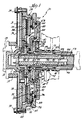
- a friction clutch assembly 10 for use with a gas turbine or similar high torque engine in a vehicle, such as an automobile, for control of the torque transmitted from the engine to drive the wheels of the vehicle.
- This assembly provides a clutch application strategy where the torque capacity must be controlled to a very small percent of the overall clutch capacity.
- the clutch assembly includes a cover plate 11 mounted on a central pilot 12 extending into the engine drive shaft 13 and a reaction plate 14 abuts the cover plate and is secured thereto by bolts 18. Grooves 15 are formed in the cover plate 11 to provide exhaust passages as will be later described.
- a flex-plate 16 on a hub 17 is secured to the engine drive shaft 13 parallel to and is also secured in spaced relation to the cover plate 11 by bolts 18.
- a clutch cover 19 is further secured to cover plate 11 to house the internal clutch structure.
- the cover includes an axially extending wall 21 terminating in a radial flange 22 secured to the periphery of the cover plate by bolts 18.
- the wall 21 also has a splined portion 23 engaging the splined periphery 25 ( Figure 3) of an annular pressure plate 24 for rotation together.
- a clutch plate 27 is secured to the radial flange 29 of a hub 28 received within a central opening in the reaction plate 14, the clutch plate having friction facings 31 secured to the periphery thereof and located between facing surfaces 32 and 33 of the reaction plate 14 and pressure plate 24, respectively.
- a Belleville spring 36 is pivotally mounted in a corner 34 of the cover 19 and is retained therein by a snap ring 38 mounted in a groove 37 in the cover. The Belleville spring bears on an annular pressure ring 41 received in a complementary groove 39 formed in the surface of the pressure plate 24 opposite to surface 33.
- the clutch cover also includes a portion 43 extending radially from an inner hub 42 and an annular recessed portion 44 between the flange 43 and corner 34.
- a single, unitary piston 45 has an inner radial portion defining a small piston area 46 opposite flange 43, an intermediate shoulder 47 and an outer radial portion defining a large piston area 48 received in the chamber 55 defined by recessed portion 44; the piston having an inner sealing ring 49 engaging the hub 42 and an intermediate ring 51 and outer ring 52 engaging the chamber 55.
- a fulcrum ridge or surface 53 on the outer radial piston portion engages the inner peripheral edge of the Belleville spring 36 extending radially inwardly of the pressure ring 41.
- a clutch hub 56 having a radial flange 57 fitting within a recess defined by the exterior surface of recessed portion 44 and abutting the flange 43 of hub 42 has a clutch hub shaft 58 secured thereto and extending rearwardly towards the vehicle transmission (not shown).
- a stationary sleeve shaft 59 is sealingly received in the clutch hub shaft 58 through axially spaced sealing rings 61 to define an annular flow passage 62 communicating with angularly disposed ports 63 in the clutch cover hub 42 leading to the chamber 54.
- a flow passage 65 leading to one or more radial passages 66 formed between the hub flange 57 and radial flange 43 of the cover and communicating with passages 67 in the shoulder 68 defining the recessed portion 44 and leading to the large chamber 55.
- a port 71 communicates with annular passage 62 and a second port 72 communicates with passage 65, the ports being sealingly separated by three seal rings 69.
- a transmission input shaft 73 extends through the sleeve shaft 59 to terminate in a splined forward end 74 received in the splined opening 75 in the clutch plate hub 28.
- An inner annular passage 76 is formed between the input shaft 73 and sleeve shaft 59 to communicate through radial ports 77 with an outer annular passage 78 between the sleeve shaft 59 and clutch hub shaft 58, which in turn is connected to a source of clutch cooling oil.
- the input shaft 73 is rotatably mounted in the sleeve shaft 59 by bearings 79 through which cooling oil flows to the interior of the clutch.
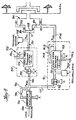
- Figures 4 and 5 disclose more detailed schematic arrangements of the hydraulic control system for the clutch piston and the electronic control system for the clutch.
- the hydraulic system for clutch control includes a pair of electro-hydraulic control valves, which valves have two stages.
- the first or pilot stage is a high response solenoid on/off valve that operates in a pulse-width modulated (PWM) mode
- PWM pulse-width modulated
- the second stage is a spool valve for actually controlling or regulating the pressure to either chamber of the clutch.
- Figure 4 discloses the hydraulic system 85 which includes apply systems 87 and 91 coupled to the line pressure inlet 86 and branch lines 86a and 86b wherein the hydraulic pressures delivered to the two clutch chambers 54 and 55 are controlled with pulse-width-modulated (PWM) solenoid valves 88 and 92.
- PWM pulse-width-modulated
- Primary control of the clutch is provided by the pressure delivered to the chamber 54 defining the small area 46 of the clutch piston 45. Under high throttle starting conditions, a bias pressure is applied to the chamber 55 defining the large piston area 48.
- the pressure levels of the hydraulic fluid delivered to the large and small piston areas are controlled with two three-way spool valves 89 and 93 driven by the PWM solenoid valves 88 and 92, respectively.
- Line pressure from inlet 86 passes through a pressure regulator 95 with the regulated pressure P REG being fed through branches 96 and 97 to the solenoid valves 88 and 92; a feedback loop 98 having an orifice 99 feeds back to the pressure regulator.
- the small clutch pressure P SC provided by the valve 89 from line pressure in line 86a is passed through line 101 to the port 71 leading into the small chamber 54, a pressure sensor 102 communicating with pressure line 101.
- the small piston area control valve 89 is an open-center valve with no hydraulic feedback.
- the control software generating the PWM duty cycle for the solenoid valve 88 driving the small area control valve 89 includes feedback compensation of errors between the measured pressure in the small area of the piston and the pressure command from the pressure control strategy.
- the large piston area control valve 93 is a closed center valve with hydraulic feedback through loop 103 which may contain an orifice 104 for damping.
- the control software computes the PWM duty cycle for the solenoid valve 92 driving the control valve 93 based on the pressure command indicated by the pressure control strategy directly.
- An accumulator 105 communicates with the line 97 between solenoid valve 92 and control valve 93 with the pulse-width-modulated pilot pressure for the control valve 93 minimizing the pressure ripple caused by the PWM signal.
- the large clutch pressure P LC provided by valve 93 from line pressure in line 86b passes through line 106 to the port 72 leading to chamber 55.
- the bias pressure for the large piston area is passed through a first-order lag circuit (not shown) before issuing the large area pressure command to avoid any sudden changes in clutch pressure.
- Both the bias set point and the lag frequency are a function of the throttle sensor voltage signal.
- the small area clutch torque command is equal to the desired clutch torque minus the expected torque generated as a result of the large piston area pressure command. This torque command is transformed into a small piston pressure command.
- the pressure command to the small piston area control valve is the sum of the pressure required to maintain the clutch touch-off position and the incremental pressure required on the small piston area to generate the commanded clutch torque.
- FIG. 5 is a block diagram of the control system for the clutch which is based on controlling the speed of the high torque engine or turbine for clutch control.
- a signal T E for the engine throttle setting is fed to a microcomputer 110 including an engine operating map or speed schedule 111 containing data for engine stall at various throttle settings.
- the operating map provides a speed set point to a comparator 112 leading to a controller 113, both in the microcomputer 110, the controller providing a signal to the two-stage pressure valve 89.
- the pressure setting from this valve is provided to the small clutch piston area 46 through line 101 and port 71.
- the clutch engagement due to the pressure developed in chamber 54 causes the engine speed to decrease and the change in engine speed provides a signal through a feedback loop 114 having a speed sensor 115.
- This signal is compared in comparator 112 with the stall speed set point, which in turn provides an altered output signal to the controller 113 to adjust the pressure valve 89.
- a second feedback loop 116 having the pressure sensor 102 takes the pressure signal from the valve 89 and provides a secondary closed loop for a signal to the comparator.
- the dual area pressure valve 93 is actuated once the small piston area 46 has completed clutch engagement. This provides pressure to the large piston chamber 55 upon an increase in engine speed by depressing the throttle.
- the large area 48 receives a pressure P LC from valve 93 based on a large area pressure schedule 118, also a part of microcomptuer 110, and provides a coarse torque adjustment through line 106 and port 72 to the large clutch area 48 for the clutch control once initial smooth engagement of the clutch has been achieved.
- the controller will switch to the large piston area 48 in chamber 55 to give the clutch its full capacity as required.
- the small piston area 46 is the "vernier" area which overcomes the force of the Belleville spring 36, and the larger piston area 48 is the main apply area. This arrangement allows an accurate smooth takeoff from a vehicle stop and provides the capability for high torque with the large piston area.
Landscapes
- Engineering & Computer Science (AREA)
- General Engineering & Computer Science (AREA)
- Physics & Mathematics (AREA)
- Fluid Mechanics (AREA)
- Mechanical Engineering (AREA)
- Hydraulic Clutches, Magnetic Clutches, Fluid Clutches, And Fluid Joints (AREA)
Claims (13)
Applications Claiming Priority (2)
| Application Number | Priority Date | Filing Date | Title |
|---|---|---|---|
| US107143 | 1987-10-09 | ||
| US07/107,143 US4875561A (en) | 1987-10-09 | 1987-10-09 | Dual clutch application area and control |
Publications (2)
| Publication Number | Publication Date |
|---|---|
| EP0311285A1 EP0311285A1 (de) | 1989-04-12 |
| EP0311285B1 true EP0311285B1 (de) | 1991-10-30 |
Family
ID=22315075
Family Applications (1)
| Application Number | Title | Priority Date | Filing Date |
|---|---|---|---|
| EP88308940A Expired - Lifetime EP0311285B1 (de) | 1987-10-09 | 1988-09-27 | Kupplung mit zwei Druckflächen und deren Steuerung |
Country Status (5)
| Country | Link |
|---|---|
| US (1) | US4875561A (de) |
| EP (1) | EP0311285B1 (de) |
| JP (1) | JP2744028B2 (de) |
| CA (1) | CA1305677C (de) |
| DE (1) | DE3865940D1 (de) |
Families Citing this family (12)
| Publication number | Priority date | Publication date | Assignee | Title |
|---|---|---|---|---|
| JP2876354B2 (ja) * | 1991-05-27 | 1999-03-31 | トヨタ自動車株式会社 | 自動変速機の油圧制御装置 |
| JPH09229090A (ja) * | 1995-12-18 | 1997-09-02 | Nsk Warner Kk | 発進クラッチ |
| US6202814B1 (en) * | 1999-08-24 | 2001-03-20 | Borgwarner Inc. | Automatic transmission having grounded clutch with convergent cooling |
| DE10257866A1 (de) * | 2002-12-11 | 2004-07-08 | Knorr-Bremse Systeme für Nutzfahrzeuge GmbH | Druckgesteuerte Reibungskupplung |
| EP1555452B1 (de) * | 2004-01-16 | 2007-01-31 | LuK Lamellen und Kupplungsbau Beteiligungs KG | Stelleinrichtung zur Übertragung von Kolbenkräften auf die Ein-/Ausrückeinrichtung einer Doppelkupplung. |
| US7104380B2 (en) * | 2004-09-15 | 2006-09-12 | Ford Global Technologies, Llc | Dual area piston for transmission clutch and sequential control therefor |
| DE102005020415A1 (de) * | 2005-04-27 | 2006-11-09 | Getrag Getriebe- Und Zahnradfabrik Hermann Hagenmeyer Gmbh & Cie Kg | Antriebseinheit für ein Kraftfahrzeug |
| AT8780U1 (de) * | 2005-05-31 | 2006-12-15 | Magna Drivetrain Ag & Co Kg | Reibungskupplung mit hydraulischem aktuator und antriebseinheit mit mindestens einer solchen |
| US7736264B2 (en) * | 2007-06-08 | 2010-06-15 | Gm Global Technology Operations, Inc. | Eight speed automatic transmission with dual area clutch piston |
| US7913828B2 (en) * | 2008-02-25 | 2011-03-29 | GM Global Technology Operations LLC | Clutch with dual area piston and independent pressure control |
| DE102012204368B4 (de) * | 2012-03-20 | 2015-02-05 | Robert Bosch Gmbh | Kraftmaschinenanordnung umfassend eine fluidbetätigte Kupplungsanordnung und einen Freilauf |
| CN106438762B (zh) * | 2016-11-30 | 2018-09-25 | 广西玉柴机器股份有限公司 | 一种混合动力离合器控制结构及方法 |
Family Cites Families (22)
| Publication number | Priority date | Publication date | Assignee | Title |
|---|---|---|---|---|
| US2876743A (en) * | 1956-03-16 | 1959-03-10 | Int Harvester Co | Counterbalancing means for hydraulically operated clutch |
| FR1223807A (fr) * | 1958-05-14 | 1960-06-20 | Borg Warner | Embrayage à commande hydraulique |
| GB1018539A (en) * | 1963-10-04 | 1966-01-26 | Ford Motor Co | Automatic change-speed transmission |
| US3273415A (en) * | 1963-12-30 | 1966-09-20 | Clark Equipment Co | Transmission |
| US3262531A (en) * | 1964-05-28 | 1966-07-26 | Twin Disc Clutch Co | Clutch with dual pistons for quick slack take up |
| AT314917B (de) * | 1970-05-21 | 1974-04-25 | Stromag Maschf | Hydraulisch betätigte Kupplung |
| DE2027413A1 (de) * | 1970-06-04 | 1971-12-23 | Licentia Gmbh | Verfahren und Einrichtung zur auto matischen Anfahrsteuerung |
| US3753478A (en) * | 1971-07-19 | 1973-08-21 | Borg Warner | Clutch with fluid operated lock |
| US4147245A (en) * | 1976-12-16 | 1979-04-03 | Tsentralny Nauchno-Issledovatelsky Avtomobilny I Avtomotorny Institut (Nami) | Hydraulically operated friction clutch |
| US4116321A (en) * | 1976-12-27 | 1978-09-26 | Borg-Warner Corporation | Valve arrangement for closed-loop control system |
| DE2714500B1 (de) * | 1977-04-01 | 1977-11-10 | Bayerische Motoren Werke Ag | Hydraulisch betaetigte Reibungskupplung,insbesondere Lamellenkupplung fuer automatische Getriebe von Kraftfahrzeugen |
| DE2941935C2 (de) * | 1979-10-17 | 1984-07-05 | Zahnradfabrik Friedrichshafen Ag, 7990 Friedrichshafen | Steuereinrichtung für eine Schaltkupplung mit Drehmomentwandler |
| JPS5733226A (en) * | 1980-08-04 | 1982-02-23 | Aisin Warner Ltd | Device for frictional engagement under two-stage control |
| JPS5786629A (en) * | 1980-11-19 | 1982-05-29 | Kamizaki Kokyu Koki Seisakusho Kk | Traveling and driving apparatus for agricultural vehicles |
| JPS58225226A (ja) * | 1982-06-22 | 1983-12-27 | Toyota Motor Corp | 摩擦クラツチの接続制御方法 |
| DE3305999C1 (de) * | 1983-02-22 | 1984-05-10 | Zahnradfabrik Friedrichshafen Ag, 7990 Friedrichshafen | Steuereinrichtung fuer eine Schaltkupplung |
| JPS60263731A (ja) * | 1984-06-13 | 1985-12-27 | Toyota Motor Corp | 摩擦係合装置の作動油圧制御装置 |
| JPS60263730A (ja) * | 1984-06-13 | 1985-12-27 | Toyota Motor Corp | 摩擦係合装置の作動油圧制御装置 |
| US4558772A (en) * | 1984-08-29 | 1985-12-17 | General Motors Corporation | Electronic control for a starting clutch |
| US4648496A (en) * | 1985-04-12 | 1987-03-10 | Borg-Warner Automotive, Inc. | Clutch control system for a continuously variable transmission |
| US4664242A (en) * | 1985-09-30 | 1987-05-12 | General Motors Corporation | Torque transmitting device having a fluid-operated piston |
| US4757886A (en) * | 1987-01-20 | 1988-07-19 | Ford Motor Company | Transmission clutch closed loop slip controller and method |
-
1987
- 1987-10-09 US US07/107,143 patent/US4875561A/en not_active Expired - Lifetime
-
1988
- 1988-09-27 CA CA000578593A patent/CA1305677C/en not_active Expired - Lifetime
- 1988-09-27 EP EP88308940A patent/EP0311285B1/de not_active Expired - Lifetime
- 1988-09-27 DE DE8888308940T patent/DE3865940D1/de not_active Expired - Lifetime
- 1988-10-07 JP JP63253640A patent/JP2744028B2/ja not_active Expired - Lifetime
Also Published As
| Publication number | Publication date |
|---|---|
| US4875561A (en) | 1989-10-24 |
| EP0311285A1 (de) | 1989-04-12 |
| CA1305677C (en) | 1992-07-28 |
| JPH01131327A (ja) | 1989-05-24 |
| JP2744028B2 (ja) | 1998-04-28 |
| DE3865940D1 (de) | 1991-12-05 |
Similar Documents
| Publication | Publication Date | Title |
|---|---|---|
| US4947970A (en) | Dual clutch control system | |
| US4706790A (en) | Gain scheduling technique for a closed loop slip control system | |
| EP0311285B1 (de) | Kupplung mit zwei Druckflächen und deren Steuerung | |
| EP0153798B1 (de) | Steuerung der Überbrückungskupplung eines Drehmomentwandlers | |
| US4724939A (en) | Closed loop clutch slip control system with turbine roughness control | |
| US5845756A (en) | Oil pressure circuit for clutch | |
| US5314385A (en) | System for cooling a starting clutch of a continuously variable transmission | |
| JP2844363B2 (ja) | 連続可変変速機制御方法 | |
| EP0274080B1 (de) | Steuersystem für die Vorwärts- und Rückwärtskupplungen eines stufenlosen Riemengetriebes | |
| US5105926A (en) | Slip control system for torque converter of automatic transmission | |
| US5054590A (en) | Control device and method for a pressure actuatable bridging coupling of a hydrodymanic torque converter | |
| US4856380A (en) | Method of controlling clutch pressure of continuously variable transmission system | |
| US4995283A (en) | Hydraulic control system for steplessly variable power transmission | |
| US4369677A (en) | Transmission throttle pressure regulator assembly | |
| US4466312A (en) | System for controlling transmission ratio of transmission for automotive vehicles | |
| US3977424A (en) | Differential pressure regulator valve for a hydrostatic transmission control system | |
| US3688606A (en) | Throttle valve actuator for an automatic vehicle transmission having engine back pressure compensation | |
| US4726261A (en) | Transmission shift control valve having fluid pressure distributor valve | |
| US4394827A (en) | Transmission control system with modified friction engaging mechanism actuating pressure | |
| EP0421142B1 (de) | Verfahren zur Steuerung der Umdrehungsgeschwindigkeit eines stufenlosen Getriebes | |
| EP0316629B1 (de) | Drucksteuerung in einem Automatikgetriebe mittels eines Elekromagneten mit einstellbarer Kraft | |
| JPH0798462B2 (ja) | 車両用油圧クラツチの油圧制御装置 | |
| EP0615080B1 (de) | Steuerungsventil für die Steuerung eines stufenlosen Getriebes | |
| US5549184A (en) | Hydrodynamic converter with a bridging coupling | |
| US4159051A (en) | Hydraulic clutch control system |
Legal Events
| Date | Code | Title | Description |
|---|---|---|---|
| PUAI | Public reference made under article 153(3) epc to a published international application that has entered the european phase |
Free format text: ORIGINAL CODE: 0009012 |
|
| AK | Designated contracting states |
Kind code of ref document: A1 Designated state(s): DE FR GB IT |
|
| 17P | Request for examination filed |
Effective date: 19890309 |
|
| 17Q | First examination report despatched |
Effective date: 19900213 |
|
| GRAA | (expected) grant |
Free format text: ORIGINAL CODE: 0009210 |
|
| AK | Designated contracting states |
Kind code of ref document: B1 Designated state(s): DE FR GB IT |
|
| ITF | It: translation for a ep patent filed | ||
| REF | Corresponds to: |
Ref document number: 3865940 Country of ref document: DE Date of ref document: 19911205 |
|
| ET | Fr: translation filed | ||
| PLBE | No opposition filed within time limit |
Free format text: ORIGINAL CODE: 0009261 |
|
| STAA | Information on the status of an ep patent application or granted ep patent |
Free format text: STATUS: NO OPPOSITION FILED WITHIN TIME LIMIT |
|
| PG25 | Lapsed in a contracting state [announced via postgrant information from national office to epo] |
Ref country code: GB Effective date: 19920927 |
|
| 26N | No opposition filed | ||
| GBPC | Gb: european patent ceased through non-payment of renewal fee |
Effective date: 19920927 |
|
| PG25 | Lapsed in a contracting state [announced via postgrant information from national office to epo] |
Ref country code: IT Free format text: LAPSE BECAUSE OF NON-PAYMENT OF DUE FEES;WARNING: LAPSES OF ITALIAN PATENTS WITH EFFECTIVE DATE BEFORE 2007 MAY HAVE OCCURRED AT ANY TIME BEFORE 2007. THE CORRECT EFFECTIVE DATE MAY BE DIFFERENT FROM THE ONE RECORDED. Effective date: 20050927 |
|
| PGFP | Annual fee paid to national office [announced via postgrant information from national office to epo] |
Ref country code: DE Payment date: 20070928 Year of fee payment: 20 |
|
| PGFP | Annual fee paid to national office [announced via postgrant information from national office to epo] |
Ref country code: FR Payment date: 20070904 Year of fee payment: 20 |