EP0311312A2 - Radar-Höhenmesssysteme - Google Patents
Radar-Höhenmesssysteme Download PDFInfo
- Publication number
- EP0311312A2 EP0311312A2 EP88309088A EP88309088A EP0311312A2 EP 0311312 A2 EP0311312 A2 EP 0311312A2 EP 88309088 A EP88309088 A EP 88309088A EP 88309088 A EP88309088 A EP 88309088A EP 0311312 A2 EP0311312 A2 EP 0311312A2
- Authority
- EP
- European Patent Office
- Prior art keywords
- output signals
- aircraft
- signals
- threshold detector
- threshold
- Prior art date
- Legal status (The legal status is an assumption and is not a legal conclusion. Google has not performed a legal analysis and makes no representation as to the accuracy of the status listed.)
- Withdrawn
Links
Images
Classifications
-
- G—PHYSICS
- G01—MEASURING; TESTING
- G01S—RADIO DIRECTION-FINDING; RADIO NAVIGATION; DETERMINING DISTANCE OR VELOCITY BY USE OF RADIO WAVES; LOCATING OR PRESENCE-DETECTING BY USE OF THE REFLECTION OR RERADIATION OF RADIO WAVES; ANALOGOUS ARRANGEMENTS USING OTHER WAVES
- G01S7/00—Details of systems according to groups G01S13/00, G01S15/00, G01S17/00
- G01S7/02—Details of systems according to groups G01S13/00, G01S15/00, G01S17/00 of systems according to group G01S13/00
- G01S7/28—Details of pulse systems
- G01S7/285—Receivers
- G01S7/292—Extracting wanted echo-signals
- G01S7/2921—Extracting wanted echo-signals based on data belonging to one radar period
- G01S7/2922—Extracting wanted echo-signals based on data belonging to one radar period by using a controlled threshold
-
- G—PHYSICS
- G01—MEASURING; TESTING
- G01S—RADIO DIRECTION-FINDING; RADIO NAVIGATION; DETERMINING DISTANCE OR VELOCITY BY USE OF RADIO WAVES; LOCATING OR PRESENCE-DETECTING BY USE OF THE REFLECTION OR RERADIATION OF RADIO WAVES; ANALOGOUS ARRANGEMENTS USING OTHER WAVES
- G01S13/00—Systems using the reflection or reradiation of radio waves, e.g. radar systems; Analogous systems using reflection or reradiation of waves whose nature or wavelength is irrelevant or unspecified
- G01S13/02—Systems using reflection of radio waves, e.g. primary radar systems; Analogous systems
- G01S13/06—Systems determining position data of a target
- G01S13/08—Systems for measuring distance only
- G01S13/10—Systems for measuring distance only using transmission of interrupted, pulse modulated waves
-
- G—PHYSICS
- G01—MEASURING; TESTING
- G01S—RADIO DIRECTION-FINDING; RADIO NAVIGATION; DETERMINING DISTANCE OR VELOCITY BY USE OF RADIO WAVES; LOCATING OR PRESENCE-DETECTING BY USE OF THE REFLECTION OR RERADIATION OF RADIO WAVES; ANALOGOUS ARRANGEMENTS USING OTHER WAVES
- G01S7/00—Details of systems according to groups G01S13/00, G01S15/00, G01S17/00
- G01S7/02—Details of systems according to groups G01S13/00, G01S15/00, G01S17/00 of systems according to group G01S13/00
- G01S7/28—Details of pulse systems
- G01S7/285—Receivers
- G01S7/34—Gain of receiver varied automatically during pulse-recurrence period, e.g. anti-clutter gain control
-
- G—PHYSICS
- G01—MEASURING; TESTING
- G01S—RADIO DIRECTION-FINDING; RADIO NAVIGATION; DETERMINING DISTANCE OR VELOCITY BY USE OF RADIO WAVES; LOCATING OR PRESENCE-DETECTING BY USE OF THE REFLECTION OR RERADIATION OF RADIO WAVES; ANALOGOUS ARRANGEMENTS USING OTHER WAVES
- G01S7/00—Details of systems according to groups G01S13/00, G01S15/00, G01S17/00
- G01S7/02—Details of systems according to groups G01S13/00, G01S15/00, G01S17/00 of systems according to group G01S13/00
- G01S7/40—Means for monitoring or calibrating
- G01S7/4004—Means for monitoring or calibrating of parts of a radar system
- G01S7/4021—Means for monitoring or calibrating of parts of a radar system of receivers
-
- G—PHYSICS
- G01—MEASURING; TESTING
- G01S—RADIO DIRECTION-FINDING; RADIO NAVIGATION; DETERMINING DISTANCE OR VELOCITY BY USE OF RADIO WAVES; LOCATING OR PRESENCE-DETECTING BY USE OF THE REFLECTION OR RERADIATION OF RADIO WAVES; ANALOGOUS ARRANGEMENTS USING OTHER WAVES
- G01S13/00—Systems using the reflection or reradiation of radio waves, e.g. radar systems; Analogous systems using reflection or reradiation of waves whose nature or wavelength is irrelevant or unspecified
- G01S13/88—Radar or analogous systems specially adapted for specific applications
- G01S13/882—Radar or analogous systems specially adapted for specific applications for altimeters
Definitions
- This invention relates to radar altimeter systems of the kind that are arranged to transmit microwave signals to the ground and to derive from received microwave signals reflected from the ground or objects on the ground information as to the height of the aircraft above the ground or objects on the ground.
- Radar altimeters are commonly used in aircraft to provide a display to the pilot as to the aircraft's height above ground. It has also been proposed to use the output from a radar altimeter to provide information to terrain referenced navigation (TRN) systems. TRN systems have a stored digital database of ground contours over which the aircraft is to fly and correlate height information from the radar altimeter with the database to derive information as to the position of the aircraft in terms of, for example, latitude and longitude.
- TRN systems have a stored digital database of ground contours over which the aircraft is to fly and correlate height information from the radar altimeter with the database to derive information as to the position of the aircraft in terms of, for example, latitude and longitude.
- Radar altimeters take one of two different forms: one uses short pulses of radar emissions, and the other uses a continuous wave, frequency modulated (FMCW) radar emission.
- the pulsed form of radar has an advantage over continuous wave equipment, in that it is more readily responsive to relatively small radar targets, such as low density woods, small hills and so on. This can be important in low flying aircraft, since the pilot needs information about his height above any possible collision object on the ground, not just information about height above the ground itself. Pulsed equipment can also be rendered less susceptible to detection from outside the aircraft, making the aircraft itself less easy to detect by hostile observers.
- pulsed radar altimeters make them less suitable for use in TRN systems since the database in such systems is usually of only the more general features such as ground contours. Correlation of the output of a pulsed radar altimeter with such a database would be more difficult than with a less sensitive continuous wave radar altimeter.
- radar altimeter is used to denote any microwave altimeter.
- an aircraft microwave altimeter system of the above-specified kind characterised in that the system includes a threshold detector that provides two sets of output signals in accordance with two respective different threshold levels, that the first set of output signals is supplied to a display, and that the second set of output signals has a lower sensitivity than the first set of output signals and is supplied to a navigation system.
- the threshold detector means may include two parallel threshold detector channels that supply the respective first and second sets of output signals in respect of the same received signals.
- the threshold detector has a single channel that is selectively adjustable in threshold sensitivity, the threshold detector being arranged to supply alternately output signals at one sensitivity level to the display and at another, lower sensitivity level to the navigation system.
- the transmitter preferably transmits pulsed microwave signals. Information derived from a greater number of reflected pulses may be supplied to the display than to the navigation system.
- the threshold detector may be responsive to the magnitude of the received signals such that the first set of output signals is provided in response to received signals above a first magnitude and the second set of output signals is provided in response to received signals above a second magnitude greater that the first magnitude.
- the threshold detector may include an amplifier that produces two sets of intermediate output signals at different gains, the threshold detector passing to the display and the navigation system respectively those of the two sets of intermediate output signals above the same threshold level.
- the threshold detector may be responsive to the duration of the received signals such that the first set of output signals is provided in response to received signals longer than a first duration and the second set of output signals is provided in response to received signals longer than a second duration, the second duration being longer than the first duration.
- the threshold detector means may be responsive to both the magnitude and duration of the received signals.
- the altimeter system may include a comparator thatreceives the first and second sets of output signals, and provides an indication when there is a difference between the first and second sets of output signals greater than a predetermined difference.
- the system may be arranged to supply only one of the sets of output signals to both the display and the navigation system when the indicator provided by the comparator indicates that the other one of the sets of output signals is faulty.
- the system may increase the sensitivity of the threshold detector if the one set of output signals is the second set of output signals.
- the threshold levels of the threshold detector may be modified in accordance with the height of the aircraft.
- the threshold levels of the threshold detector may be modified in accordance with the terrain conditions over which the aircraft is flying.
- the threshold levels of the threshold detector may be modified in accordance with the flight conditions of the aircraft.
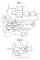
- the system include a conventional pulsed microwave transmitter 1 that supplies signals to an antenna 2 which directs a pulsed beam of microwave energy towards the ground 3.
- Energy reflected from the ground 3, and objects 4 on the ground, is received by a second antenna 5 which supplies signals to a conventional receiver 6.
- the receiver 6 supplies an output to a detector 7 which in turn provides an output to a threshold detector 8 via a video amplifier 9.
- the threshold detector 8 may take several different forms which each provide two sets of output signals, on lines 11 and 12 at different threshold sensitivity levels.
- the threshold detector 8 shown in Figure 1 comprises two separate threshold detector circuits arranged as parallel channels 13 and 14 which both receive the same inputs from the video amplifier 9.
- Each channel 13 and 14 has its own threshold detector 15 and 16 respectively which supplies output signals to a respective digital height converter 17 and 18.
- one of the detectors 15 has a relatively low threshold, high sensitivity so that all radar return signals with a magnitude above a noise level are passed by the detector as a first set of output signals.
- return signals from small, low density woods, from building and small hills will be supplied to the converter 17.
- the converter 17 derives a measure of the distance/height associated with the signal passed by the detector 15 by measurement of the time interval between transmission and reception of the radar signal, the converter 17 receiving a signal on line 20 from the transmitter 1 on each pulse transmission.
- the converter 17 also supplies an output signal on line 21 to control the threshold level of the detector 15 in accordance with height, the threshold being reduced, and sensitivity thereby increased, at greater heights to compensate for the reduction in signal amplitude with height.
- the height signal output from the converter 17 is supplied via line 11 to a pilot's head-up display 30 so that information is presented to the pilot about the clearance of the aircraft from the ground and ground obstacles.
- the other detector 16 in the second channel 14 is set with a higher threshold, lower sensitivity so that only those radar returns from the ground or large objects are passed by the detector as a second set of output signals to the associated digital height converter 18.
- the output of the converter 18 thereby provides height information of major ground contours.
- An output from the converter 18 is also supplied to the detector 16 to control the threshold level with height, as in the other detector 15.
- the output from the converter 18 is supplied via line 12 to a terrain referenced navigation system 31 of known kind.
- the navigation system 31 includes a database of ground contours and may also include an inertial navigation system. Because the stored information is in respect only of major ground features, the output signals on line 12 are readily correlated with this.
- the altimeter system may also include a comparator 50 that receives the two outputs on lines 11 and 12 and compares their values. If the signals differ by more than a predetermined amount, equivalent to the height of the tallest object likely to be included in the signal on line 11, but not in the signal on line 12, the comparator 50 indicates a discrepancy to the pilot.
- the comparator 50 could produce an output to the navigation system 31 so that it is caused to operate only on the inertial navigation system without TRN updating. If a fault should occur in signals on one line 11 or 12, or in one channel 13 or 14, this could be partly rectified by supplying signals derived from the non-faulty line or channel to both the display 30 and the navigation system 31. If the higher sensitivity channel 14 should be faulty, the sensitivity of the other channel 13 could be increased and signals at this high sensivity supplied to both the display 30 and the navigation system 31 to ensure safe flight at the expense of accurate navigation.
- the threshold levels in the detectors 15 and 16 could be preset in hardware of the detectors or by software programming prior to flight. Alternatively, the threshold levels could be adjusted by a processor 51 according to flight or terrain conditions.
- the database in the navigation system could be programmed with information about the nature of the ground surface, such as forested, built-up, flat water, hilly and so on. This information could be supplied to the processor 50 to cause it to modify the threshold level of one or both detectors 15 or 16, as appropriate.
- An alternative threshold detector 8 is shown in Figure 2, which has a single threshold detector circuit 60 that receives the video output pulses from the amplifier 9.
- the threshold level of the detector circuit 60 is controlled by a control unit 61 which also receives signals from the amplifier. Output signals from the detector circuit 60 are supplied via a digital height converter 62 to a gate 63 which is controlled by the control unit 61 to supply the signal either to line 11 or to line 12.
- the control unit 61 alternately sets the detector 60 to a high threshold, low sensitivity and to a low threshold, high sensitivity.
- the control unit 61 sets the gate 63 to pass the output signal to the display 30 via line 11; when the detector is set at a high threshold, the gate 63 switches to supply the output of the detector to the navigation system 31, via line 12.
- the output derived from each radar pulse may be supplied to the display, except for one pulse in every ten which is supplied by the gate 63 to the navigation system.
- the system of the present invention enables a high sensitivity output to be supplied to the display and a lower sensitivity output supplied to the navigation system without the need to duplicate the radar altimeter.
- the comparator also enables a check to be provided of system integrity.
- the display need not be a visual display, but could, for example, provide an audible output, such as a warning when the aircraft is too low to ground objects.
- the invention could be used with other radar altimeter systems such as FMCW system.
- the threshold detector need not necessarily operate by setting two different threshold levels above which signals are passed. Instead, only one threshold level could be set and two sets of intermediate output signals at respective different gains supplied to the detector circuit. The detector circuit would pass those of the two sets of intermediate output signals above the same threshold level. In this way, two sets of output signals would be produced for supply to the display and navigation equipment at different sensitivity levels. In such an arrangement, the amplifier or other means by which the gain is varied is regarded as forming a part of the threshold detector means.
- the threshold detector need not respond to the magnitude of signals, but could instead respond to their duration, since signal returns from small objects will have a shorter duration as well as a lower magnitude.
- the shorter duration signals only being supplied to the display means, the threshold detector could be responsive to both magnitude and duration, such as by integrating the signals.
Landscapes
- Engineering & Computer Science (AREA)
- Radar, Positioning & Navigation (AREA)
- Remote Sensing (AREA)
- Computer Networks & Wireless Communication (AREA)
- Physics & Mathematics (AREA)
- General Physics & Mathematics (AREA)
- Radar Systems Or Details Thereof (AREA)
Applications Claiming Priority (4)
| Application Number | Priority Date | Filing Date | Title |
|---|---|---|---|
| GB8723566 | 1987-10-07 | ||
| GB878723566A GB8723566D0 (en) | 1987-10-07 | 1987-10-07 | Radar altimeter systems |
| GB878727756A GB8727756D0 (en) | 1987-11-27 | 1987-11-27 | Radar altimeter systems |
| GB8727756 | 1987-11-27 |
Publications (2)
| Publication Number | Publication Date |
|---|---|
| EP0311312A2 true EP0311312A2 (de) | 1989-04-12 |
| EP0311312A3 EP0311312A3 (de) | 1990-12-12 |
Family
ID=26292847
Family Applications (1)
| Application Number | Title | Priority Date | Filing Date |
|---|---|---|---|
| EP19880309088 Withdrawn EP0311312A3 (de) | 1987-10-07 | 1988-09-30 | Radar-Höhenmesssysteme |
Country Status (3)
| Country | Link |
|---|---|
| US (1) | US4894659A (de) |
| EP (1) | EP0311312A3 (de) |
| GB (1) | GB2210752B (de) |
Cited By (5)
| Publication number | Priority date | Publication date | Assignee | Title |
|---|---|---|---|---|
| FR2653620A1 (fr) * | 1989-10-24 | 1991-04-26 | Mitsubishi Electric Corp | Carte a circuit integre sans contact. |
| EP0475181A3 (en) * | 1990-08-28 | 1993-05-26 | Honeywell Inc. | Aircraft radar altimeter |
| US6045042A (en) * | 1989-10-24 | 2000-04-04 | Mitsubishi Denki Kabushiki Kaisha | Non-contact IC card having multiple receivers with different signal detection threshholds for minimizing current consumption |
| CN110515095A (zh) * | 2019-09-29 | 2019-11-29 | 北京智行者科技有限公司 | 基于多个激光雷达的数据处理方法及系统 |
| WO2022039708A1 (en) * | 2020-08-19 | 2022-02-24 | Roketsan Roket Sanayi̇i̇ Ti̇caret A.Ş. | Sensor system with microwave altimeter and a method thereof |
Families Citing this family (9)
| Publication number | Priority date | Publication date | Assignee | Title |
|---|---|---|---|---|
| US5335181A (en) * | 1992-01-15 | 1994-08-02 | Honeywell Inc. | Terrain referenced navigation--woods data base model |
| US5331562A (en) * | 1992-01-16 | 1994-07-19 | Honeywell Inc. | Terrain referenced navigation-adaptive filter distribution |
| FR2690754B1 (fr) * | 1992-04-30 | 1994-06-10 | Thomson Csf | Procede de detection et de localisation d'objets sur un sol relativement plan et dispositif de mise en óoeuvre. |
| US5886662A (en) * | 1997-06-18 | 1999-03-23 | Zai Amelex | Method and apparatus for remote measurement of terrestrial biomass |
| SE515860C2 (sv) | 2000-02-14 | 2001-10-22 | Saab Dynamics Ab | Anläggning samt förfarande för navigering av en farkost |
| US8232910B1 (en) * | 2007-08-31 | 2012-07-31 | Rockwell Collins, Inc. | RTAWS active tower hazard detection system |
| US9081094B2 (en) * | 2012-02-22 | 2015-07-14 | Honeywell International Inc. | Aircraft radar altimeter structure |
| US11348468B1 (en) | 2019-03-15 | 2022-05-31 | Rockwell Collins, Inc. | Systems and methods for inhibition of terrain awareness and warning system alerts |
| US11482122B2 (en) * | 2020-02-04 | 2022-10-25 | Honeywell International Inc. | Methods and systems for monitoring a fault condition of a radar altitude device |
Family Cites Families (7)
| Publication number | Priority date | Publication date | Assignee | Title |
|---|---|---|---|---|
| US3213451A (en) * | 1963-03-29 | 1965-10-19 | Frederick C Alpers | Airborne contour-sensing radar |
| US3277467A (en) * | 1964-12-16 | 1966-10-04 | Texas Instruments Inc | Time sharing radar-altimeter |
| US3603989A (en) * | 1965-06-07 | 1971-09-07 | Us Navy | Two-stage radar system |
| US3742438A (en) * | 1970-11-10 | 1973-06-26 | Simrad As | Echo sounding apparatus with automatically regulated receiver gain |
| US3781530A (en) * | 1972-04-03 | 1973-12-25 | Secr Defence | Navigational apparatus |
| US4174520A (en) * | 1978-02-13 | 1979-11-13 | Canadian Patents & Development Limited | Radar altimeter for tropical areas |
| US4698635A (en) * | 1986-03-02 | 1987-10-06 | The United States Of America As Represented By The Secretary Of The Navy | Radar guidance system |
-
1988
- 1988-09-30 EP EP19880309088 patent/EP0311312A3/de not_active Withdrawn
- 1988-10-04 US US07/253,029 patent/US4894659A/en not_active Expired - Fee Related
- 1988-10-05 GB GB8823348A patent/GB2210752B/en not_active Expired - Fee Related
Cited By (5)
| Publication number | Priority date | Publication date | Assignee | Title |
|---|---|---|---|---|
| FR2653620A1 (fr) * | 1989-10-24 | 1991-04-26 | Mitsubishi Electric Corp | Carte a circuit integre sans contact. |
| US6045042A (en) * | 1989-10-24 | 2000-04-04 | Mitsubishi Denki Kabushiki Kaisha | Non-contact IC card having multiple receivers with different signal detection threshholds for minimizing current consumption |
| EP0475181A3 (en) * | 1990-08-28 | 1993-05-26 | Honeywell Inc. | Aircraft radar altimeter |
| CN110515095A (zh) * | 2019-09-29 | 2019-11-29 | 北京智行者科技有限公司 | 基于多个激光雷达的数据处理方法及系统 |
| WO2022039708A1 (en) * | 2020-08-19 | 2022-02-24 | Roketsan Roket Sanayi̇i̇ Ti̇caret A.Ş. | Sensor system with microwave altimeter and a method thereof |
Also Published As
| Publication number | Publication date |
|---|---|
| GB2210752A (en) | 1989-06-14 |
| US4894659A (en) | 1990-01-16 |
| GB8823348D0 (en) | 1988-11-30 |
| GB2210752B (en) | 1991-05-29 |
| EP0311312A3 (de) | 1990-12-12 |
Similar Documents
| Publication | Publication Date | Title |
|---|---|---|
| US5923282A (en) | Radar system | |
| US4894659A (en) | Radar altimeter systems | |
| US4910526A (en) | Airborne surveillance method and system | |
| EP0653643B1 (de) | Verfahren und Vorrichtung zum Überwachen von Fahrzeugen | |
| CA2082174C (en) | High doppler rate high altitude capability coherent pulsed doppler radar altimeter | |
| US6430480B1 (en) | Autonomous landing guidance system | |
| EP0475181B1 (de) | Flugzeug-höhenmesser | |
| US4138657A (en) | Shipboard apparatus for measuring ocean currents | |
| US5081457A (en) | Apparatus for reducing synchronous fruit in tcas surveillance systems | |
| US4370656A (en) | Use of bistatic radar system for determining distance between airborne aircraft | |
| USRE32368E (en) | Collision avoidance system for aircraft | |
| US20100033368A1 (en) | Method of Using A Microwave and Millimeter Frequency Bistatic Radar for Tracking and Fire Control | |
| US8102304B2 (en) | Distance measuring equipment and distance measuring equipment monitor system | |
| DE602004002594T2 (de) | Radar-höhenmesser mit zusätzlich vorwärts gerichteter entfernungsmessung | |
| US3829858A (en) | Arrangement in a radar equipment for indicating a variable threshold level on the indicator | |
| US4306239A (en) | Microwave landing systems | |
| US5138587A (en) | Harbor approach-defense embedded system | |
| RU2694891C1 (ru) | Способ функционирования импульсно-доплеровской бортовой радиолокационной станции истребителя при обеспечении энергетической скрытности её работы на излучение | |
| US4322730A (en) | Controlled delay gate stealer | |
| US3159832A (en) | Anti-collision device for aircraft | |
| US3296615A (en) | Identification and recognition system | |
| US4688043A (en) | High resolution radar system | |
| KR960704238A (ko) | 레이더 장치(Rader apparatus) | |
| JP2830610B2 (ja) | 二次監視レーダ装置 | |
| US4502052A (en) | Passive data acquisition and analysis system for microwave |
Legal Events
| Date | Code | Title | Description |
|---|---|---|---|
| PUAI | Public reference made under article 153(3) epc to a published international application that has entered the european phase |
Free format text: ORIGINAL CODE: 0009012 |
|
| AK | Designated contracting states |
Kind code of ref document: A2 Designated state(s): DE ES FR IT |
|
| PUAL | Search report despatched |
Free format text: ORIGINAL CODE: 0009013 |
|
| AK | Designated contracting states |
Kind code of ref document: A3 Designated state(s): DE ES FR IT |
|
| 17P | Request for examination filed |
Effective date: 19901227 |
|
| 17Q | First examination report despatched |
Effective date: 19921020 |
|
| STAA | Information on the status of an ep patent application or granted ep patent |
Free format text: STATUS: THE APPLICATION IS DEEMED TO BE WITHDRAWN |
|
| 18D | Application deemed to be withdrawn |
Effective date: 19930302 |