EP0311328A2 - Verfahren und Vorrichtung zum Steuern des Radschlupfes in einem Kraftfahrzeug mit ständigem Vierradantrieb - Google Patents
Verfahren und Vorrichtung zum Steuern des Radschlupfes in einem Kraftfahrzeug mit ständigem Vierradantrieb Download PDFInfo
- Publication number
- EP0311328A2 EP0311328A2 EP88309167A EP88309167A EP0311328A2 EP 0311328 A2 EP0311328 A2 EP 0311328A2 EP 88309167 A EP88309167 A EP 88309167A EP 88309167 A EP88309167 A EP 88309167A EP 0311328 A2 EP0311328 A2 EP 0311328A2
- Authority
- EP
- European Patent Office
- Prior art keywords
- axle
- drive
- drive mechanism
- torque
- output
- Prior art date
- Legal status (The legal status is an assumption and is not a legal conclusion. Google has not performed a legal analysis and makes no representation as to the accuracy of the status listed.)
- Granted
Links
Images


Classifications
-
- B—PERFORMING OPERATIONS; TRANSPORTING
- B60—VEHICLES IN GENERAL
- B60K—ARRANGEMENT OR MOUNTING OF PROPULSION UNITS OR OF TRANSMISSIONS IN VEHICLES; ARRANGEMENT OR MOUNTING OF PLURAL DIVERSE PRIME-MOVERS IN VEHICLES; AUXILIARY DRIVES FOR VEHICLES; INSTRUMENTATION OR DASHBOARDS FOR VEHICLES; ARRANGEMENTS IN CONNECTION WITH COOLING, AIR INTAKE, GAS EXHAUST OR FUEL SUPPLY OF PROPULSION UNITS IN VEHICLES
- B60K17/00—Arrangement or mounting of transmissions in vehicles
- B60K17/34—Arrangement or mounting of transmissions in vehicles for driving both front and rear wheels, e.g. four wheel drive vehicles
- B60K17/344—Arrangement or mounting of transmissions in vehicles for driving both front and rear wheels, e.g. four wheel drive vehicles having a transfer gear
- B60K17/346—Arrangement or mounting of transmissions in vehicles for driving both front and rear wheels, e.g. four wheel drive vehicles having a transfer gear the transfer gear being a differential gear
- B60K17/3462—Arrangement or mounting of transmissions in vehicles for driving both front and rear wheels, e.g. four wheel drive vehicles having a transfer gear the transfer gear being a differential gear with means for changing distribution of torque between front and rear wheels
- B60K17/3465—Arrangement or mounting of transmissions in vehicles for driving both front and rear wheels, e.g. four wheel drive vehicles having a transfer gear the transfer gear being a differential gear with means for changing distribution of torque between front and rear wheels self-actuated means, e.g. differential locked automatically by difference of speed
-
- Y—GENERAL TAGGING OF NEW TECHNOLOGICAL DEVELOPMENTS; GENERAL TAGGING OF CROSS-SECTIONAL TECHNOLOGIES SPANNING OVER SEVERAL SECTIONS OF THE IPC; TECHNICAL SUBJECTS COVERED BY FORMER USPC CROSS-REFERENCE ART COLLECTIONS [XRACs] AND DIGESTS
- Y10—TECHNICAL SUBJECTS COVERED BY FORMER USPC
- Y10S—TECHNICAL SUBJECTS COVERED BY FORMER USPC CROSS-REFERENCE ART COLLECTIONS [XRACs] AND DIGESTS
- Y10S188/00—Brakes
- Y10S188/01—Panic braking
Definitions
- This invention relates to multiple drive axle vehicles, such as four wheel drive vehicles, and more particularly to a mechanism adapted to receive an input torque from a prime mover and to transmit a variable torque to a plurality of drive axles through a first or second drive path system.
- One approach to solving the problems inherent in positive four wheel drive systems is to provide a manually operable jaw clutch between the drive axles thereof.
- the provision of a manually operable jaw clutch in the system allows disconnection of one axle from the power source.
- Vehicle's incorporating such manual jaw clutches are used as two wheel drive systems the vast majority of the time. As such, this system fails to provide the handling and performance benefits afforded by a full-time four wheel drive system.
- Another known system has a center differential which provides an equal torque split to the front and rear drive axles of the vehicle. Instead of bevel gears, this system includes a multitude of crossed axis or worm gears to add mechanical friction. By such construction, some additional torque is transferred from the faster to the slower turning drive axle in substantial proportion to the input torque. This system does not and cannot distinguish which axle is turning faster. Moreover, this system does not distinguish whether the difference in axle speeds results from wheel slip or by steering into a turn. Of course, when turning any additional torque transfer is detrimental to handling and can be unsafe on slippery surfaces.
- a currently used system has a viscous clutch arranged in parallel with a center differential.
- This design uses approximately 50 or more plates in a sealed clutch housing nearly filled with a silcone fluid having a carefully selected viscosity.
- the clutch transfers torque from the faster to the slower turning axle in a manner roughly proportional to the speed difference between the axles.
- Such torque transfer is effected without distinction as to which axle may be turning faster.
- such torque transfer is affected without regard to whether the speed difference is due to wheel slip or steering.
- the present invention tests this need by taking a unique approach to the design of a two axle drive mechanism adapted for use with a full-time four wheel drive vehicle. In designing this system a high priority was assigned to vehicle handling and safety on slippery wet surfaces. Unlike other systems, an understanding of the present invention begins with the tire to road interface and involves an initial determination of the minimum dynamic weight ratio at the front axle at maximum vehicle thrust.
- the center differential includes a gear set having an input member drivably connected to two output members.
- a salient of the present invention is an appreciation that the center differential should have an initial effective torque split ratio to the front axle which is several percent less than the minimum dynamic weight ratio initially calculated. As such, the differential can induce an overrun ratio which would cause rear wheel slip which is several percent more than front wheel slip.
- the next step in the design process involves calculating the traction coefficient for the front and rear pairs of road wheels.
- the next step involves determining the difference in wheel slip between the front and rear pairs of road wheels at maximum thrust on wet roads. Having determined the difference in wheel slip, the output members of the differential may be connected to the drive axles such that the output member connected to the front, steerable wheels overruns the other output member by an amount determined from the specific data used to determine wheel slip.
- the next step involves the capability of transferring torque through a second torque transfer path before the vector combination of horizontal forces exceeds the traction limit at the affected axle. That is, excess torque should be transferred before the wheels lose traction with the road and without imparting a shock load to the vehicle.
- the two axle drive mechanism includes a center differential having an input member and two output members driven by that input member.
- the center differential comprises a planetary gear set arrangement.
- Each of the output members of the differential is connectable to a drive axle of the vehicle.
- the proposed center differential defines a first torque transfer path having a predetermined initial effective torque split to the front axle which is several percent less than the minimum dynamic weight ratio on the front axle. The initial torque split is selected for the specific weight distribution of the vehicle to assure that rear wheel slip slightly exceeds front wheel slip.
- the output members are connectable to the drive axles of the vehicle such that the output member associated with the front drive axle normally overruns the other output member by a predetermined several percent when both axles are turning at the same speed.
- the present invention also includes a clutch mechanism arranged in parallel with the differential for connecting any two of the differential members in a manner permitting overrun of the output associated with the front drive axle member relative to the other output member in both forward and reverse vehicle directions.
- the clutch mechanism comprises an overrunning clutch having a drive member, a driven member, and a series of rollers therebetween.
- the driven member normally overruns the driving member by a predetermined several percent established through the manner by which the output members are connected to their respective drive axles.
- the clutch mechanism instantaneously engages when the first member ceases to overrun the other output member.
- the clutch mechanism defines a second torque transfer path for transferring excess driving or braking torque from one drive axle to the other before the affected axle reaches its traction limit.
- the driven member of the clutch mechanism may be operably connected to the front drive axle through a lost motion mechanism.
- the lost motion mechanism permits angular displacement of the output drive shaft connected to the front axle relative to the output member of the center differential connected thereto. The amount of angular displacement or free travel will be somewhat greater than the total backlash plus wind-up (torsional deflection) of the entire front axle driveline at full torque.
- the lost motion mechanism prevents inadvertent operation of the clutch mechanism and permits the transmission to be shifted between forward and reverse without closing the engine throttle and bringing the vehicle to a full stop.
- a primary object of this invention is the provision of a full-time two axle drive mechanism which allows a vehicle substantially the same levels of acceleration and safety on slippery wet roads as single axle drives offer on dry roads.
- Another object of this invention is the provision of a self contained, passively controlled two axle drive mechanism which can provide a stepless or variable torque split to the front axle of a vehicle.
- the torque split can range from under thirty percent (30%) when the front road wheels are on ice to over ninety percent (90%) when the rear wheels are on ice. This torque split can be affected in both vehicle directions and without resistance to the front wheels overrunning the rear wheels because the vehicle is in a turn.
- Another object of this invention is the provision of a two axle drive mechanism having a first torque transfer path effecting a predetermined initial torque split of input torque in a manner assuring that rear wheel slip slightly exceeds front wheel slip and which further includes a second torque transfer path for transferring excess driving torque from one drive axle to the other drive axle before the former reaches its traction limit in vector combinations of forward and lateral forces.
- the invention comprises the devices, combination and arrangement of parts as illustrated in the presently preferred form of the invention which is hereinafter set forth in detail to enable those skilled in the art to readily understand the function, operation, construction and advantages of same when read in conjunction with the accompanying drawings in which;
- the apparatus of the present invention may be used in combination with a four wheel drive vehicle 10.
- the vehicle 10 includes a chassis or frame 12 to which are mounted front and rear pairs of road or traction wheels 14, 16, respectively.
- a front drive axle assembly 18 including a front differential 20 mounts the front pair of road wheels 14 to the frame.
- the front drive axle 18 is mounted to the frame 12 in a manner persetting steering control of wheels 14 by a steering mechanism (not shown).
- a rear drive axle assembly 22 including a rear differential 24 mounts the rear pair of road wheels 16 to the frame.
- the vehicle 10 further includes a power train comprised of a prime mover or engine 26, a transmission 28 and a two axle drive mechanism 30 for concomitantly driving both the front and rear pairs of wheels.
- the transmission 28 is conditionable to move the vehicle in either forward or reverse directions.
- the mechanism 30 is connectable to an output drive shaft 32 extending from the transmission 28.
- Mechanism 30 is adapted to transmit or transfer torque in a predetermined manner to output shafts 34 and 36.
- the rearwardly extending output shaft 34 extends from drive 30 to the rear differential 24 to transmit rotary power and torque to the rear drive axle assembly 22 and ultimately, to the rear wheels 16.
- the forwardly extending output shaft 36 extends from drive 30 to the front differential 20 to transmit rotary power and torque to the front drive axle assembly 18 and, ultimately, to the front wheels 14.
- a preferred embodiment of the two axle drive mechanism for a longitudinally disposed power train arrangement is illustrated in Figure 2.
- a two axle drive mechanism for a transverse power train looks quite different.
- the components of the mechanism 30 are housed in a substantially fluid tight casing or housing 38.
- the mechanism 30 comprises, generally, a differential gear set 40 defining a first torque transfer path for dividing torque in a predetermined manner to each pair of driven road wheels and operative means 42, responsive to either forward or reverse directions of travel of the vehicle, defining a second path through which torque may be transfered from the rear wheels to the front wheels.
- the differential gear set includes a planetary gear arrangement which is operative to bias torque between an input member and two output members all of which are coupled in a predetermined drive relationship.
- the terms “differential” and “differential unit” mean a mechanical connection which divides the torque between the front and rear wheels at a ratio selected as a function of vehicle characteristics.
- the presently preferred differential comprises a planetary gear set 40 including at least three revolubly mounted elements or members which are coupled in a predetermined relationship to each other and which can be driven in either forward or reverse directions. More specifically, the planetary gear set includes a sun gear element 44, an annulus or ring gear element 46, and a planet carrier 48 carrying a series of planet gears 50, only one of which is shown in Figure 2. Each planet gear 50 intermeshs with both the sun and ring gear elements 44 and 46, respectively.
- the gear arrangement is designed to establish an effective torque split to the front axle of the vehicle which is several percent less than the minimum dynamic Weight ratio on the front axle.
- the output drive shaft 32 extending from the transmission is coaxially positioned with the differential gear set 40.
- the planet carrier 48 has a spline connection 60 with a step portion 54 on shaft 32.
- the planet carrier 48 and planet gears 50 driven thereby serve as an input drive member for the differential gear set. That is, the planetary gears 50 arranged on the planet carrier 48 drive the sun gear and ring gear elements 44 and 46, respectively; the latter two elements serving as output members for the differential gear set.
- the gear teeth on the ring gear element 46 are internally formed on the inner surface of a cylindrical portion 62 of a cup shaped member 64 having an integrally formed stem portion defining an output shaft or member 66 and a part of which is rotatably supported in the housing 8 by a bearing 68.
- the output shaft 66 may be drivingly connected to the rear pair of road wheels 16 by the rear output shaft 34, rear differential 24, and rear drive axle assembly 22.
- the sun gear element 44 of the gear set 40 is of multipiece construction. That is, the sun gear element 44 comprises a first gear section 70 disposed in driving engagement with the planetary gears 50, a sleeve section 72 spline connected at one end to the first gear section 70 and telescopically arranged about a step portion 56 on shaft 32 but revolubly mounted relative thereto, and a second gear section 74 spline connected to the other end of sleeve section 72.
- This second gear section 74 includes an axially orientated annular recess 76 arranged to overlay a reduced end portion 78 of a funnel shaped thrust member 80 secured to housing 38.
- Suitable bearing means 82 and 84 may be disposed between thrust member 80 and the second gear section 74 to support and thrust the latter for rotation about the axis of shaft 32.
- the sun gear element 44 is drivingly connectable to the front axle.
- Different forms of driving connections between the output element 44 and the front axle may be provided depending on engine disposition and other factors.
- the form of driving connection is not important or critical to the invention. What is important is that the output members of the gear set be connected to their respective drive axles such that a speed differentiation is created between the output members of the gear set. More specifically, the output element 44 should be connected such that it overspeeds or overruns the other output element by a predetermined several percent when the front and rear pair of road wheels are turning at the same speed.
- an output shaft 86 is spaced laterally from and parallel to the output shaft 66 and is rotatably supported in a lower end of housing 38 by bearings 88 and 90.
- the forward end of shaft 86 is drivingly connected to the front pair of road wheels 10 through the front output shaft 36, front differential 20, and the front drive axle assembly 18 so as to concommitantly drive the front wheels 14 with the rear wheels 16.
- an annular hub member 92 is splined to the output shaft 86 for rotation therewith.
- the hub member 92 on output shaft 86 and the second gear section 74 of sun gear element 44 are connected by a force transfer means 94 in the form of a drive chain.
- the second gear section 74, hub member 92, and force transfer means 94 define the driving connection which provides for normal overspeeding of the sun gear element 44 relative to the output member.
- the sun gear element 44 is rotated at a predetermined several percent more than the rotation of the other output element 64 of the gear set.
- the driving means 42 includes a bidirectional overrunning clutch having concentrically arranged first and second races 102 and 104, respectively.
- the first or drive race 102 has a spline connection 105 with a cylindrical sleeve extension 106 provided on the pinion carrier 48.
- the drive race turns with the pinion carrier regardless of its direction of movement and, thus, allows the bidirectional clutch mechanism 42 to respond to rotation of the input drive member of the gear set.
- the first or drive race element 102 comprises an external surface having a plurality of cam surfaces 108 thereon.
- each cam surface 108 is provided with oppositely directed ramp sections 110 and 112 with a center section or portion 114 (Fig. 5) disposed therebetween. It is within the scope of this invention, however, to design the cam surface 108 as a tangential flat on the periphery of race 102.
- the second or driven race 104 is drivingly connected to turn with the sun gear element and has an internal cylindrical race surface 116.
- the interior cylindrical surface 116 of the outer race 104 and the outer cam surface 108 of drive member 102 define an angular space therebetween which is occupied by a series of rollers 118 arranged for movement between an engaged or driven position and disengaged or free running position.
- the position of the rollers 118 when the vehicle is driven in reverse is illustrated in Figure 3.
- the position of the wedging elements when the vehicle is driven in a forward mode is illustrated in Figure 4.
- the roller clutch elements are mounted in a roller cage 120.
- the cage or element 120 has a plurality of openings 122 generally corresponding to the dimensions of the rollers 118 to accurately space the rollers 118 during operation of the device.
- the drag spring mechanism 124 includes a friction plate 126 which projects radially outward from its drive connection with the roller cage 120.
- the outer portion or free end of the plate 126 is interposed between two spring biased pressure plates 128 and 130 grounded to the housing 38.
- This combination provides a frictional drag to the roller cage 120, which maintains the clutch mechanism in an energized state in both directions of rotation.
- the cage 120 may be carried by the slower turning ring gear element 64.
- the purpose of mechanism 124 is to maintain the rollers 118 in driving contact with the inner race to allow for instantaneous clutch engagement.
- the pressure plates need to apply only a small fraction of a foot pound of friction drag to the plate 126. Other arrangements having cam surface 108 on the outer race would require much more drag.
- Still another salient feature of the present invention is the provision of a lost motion mechanism which permits angular displacement of the front drive line components relative to the driven race associated therewith.
- an extension 142 is provided in combination with the second gear section 74 of the sun gear element 44.
- the extension 142 is provided with an annular recessed area 144.
- the driven race 104 of the bidirectional clutch mechanisms 42 is accommodated within the recess 144.
- the radial contact areas on race 104 are relieved to minimize cold viscous friction.
- the driven race 104 has a plurality of radially extending projections or teeth 146 which extend into circumferentially elongated slots or recesses 148 provided on extension 142.
- each slot 148 is greater than the width of each tooth associated therewith. That is, the lash provided for by the lost motion mechanism must equal or exceed the total lash in the entire front drive line plus its "wind-up" or torsional deflection at full torque.
- the front output shaft 86 drivingly associated with the driven race 104, has a considerable degree of free angular displacement when shaft 32 forcibly reverses direction.
- An anti- rattle mechanism 150 may be provided in combination with the clutch mechanism for torsionally rough power trains.
- Such a mechanism may include a resilently biased plunger 151 which lightly acts against the outer race 104 to limit the minimum hot friction between race 104 and recessed area 144. The total mechanical and viscous friction should not exceed one fourth the amount of friction applied to disc 126 by the drag spring mechanism 124.
- a vehicle having the following characteristics may be used: 105 ⁇ wheel base; a curb weight of 3330 lbs.; a 21.75 ⁇ center of gravity height with tires having 12 ⁇ rolling radius; a front longitudinally disposed engine capable of producing 220 foot lbs. of torque and 165 horsepower at 4200 engine RPM'S; and, a 13.54/1 overall low ratio with performance ratio axles. With rear biased loading, the minimum static weight ratio on the front axle is 54%.
- the method for determining design parameters of the drive mechanism 30 involves an initial calculation of the maximum thrust developed by the vehicle. With the above example, the maximum thrust developed by the vehicle approximately equals 2800 lbs. Next, the dynamic weight transfer is calculated. With the above example, this approximately equals -580 lbs. at the front axle and +580 lbs. at the rear axle. The next step in the process is to determine the static and dynamic axle loads and minimum dynamic weight ratio. With the above example, the axle loads and dynamic weight ratio calculate as follows: axle Load: Front, F Rear R Total, T Ratio. F/T Axle Load: Front, F Rear, R Total, T Ratio, F/T Empty 2030 lbs. 1300 lbs. 3330 61% Loaded 2220 lbs. 1880 lbs. 4100 54% (Min.) Dynamic 1640 lbs. 2460 lbs. 4100 40% (Min.)
- the next step in the process is to select the initial torque split to the front drive axle.
- the initial torque split to the front drive axle should be a few percent less than the minimum dynamic weight ratio on the front axle. In this embodiment, 36% has tentatively been chosen.
- the next step in the process involves a calculation of axle thrusts for 2800 lbs. of total thrust.
- the traction coefficient for the front wheels approximately equals .61 ⁇ and the traction coefficient for the rear wheels approximately equals .728 ⁇ .
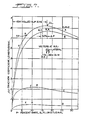
- This selection determines the transition point (T.P. on Curve A) whereat the clutch mechanism smoothly engages to transfer torque through the second torque transfer path well before the rear wheels reach their traction limit on wet pavement. This is accomplished by making a normal overrun of the output member associated with the front drive axle equal to 1.032/1. In this manner, the normal overrun ceases and the clutch mechanism 2542 engages. Upon clutch engagement, the difference in wheel slip between the front and rear axles is maintained constant by the clutch mechanism and the wheel slip is determined by the ⁇ curves. Whereas, in the first mode of operation, the initial torque split is maintained by the gear set and the difference in wheel slip was determined by the ⁇ curves. In both modes of operation, the tire to road interface data provides the essential information. Given that engagement of the clutch mechanism will maintain a constant wheel slip difference in the second mode of operation, it is then possible to plot the limiting safe ⁇ values available for other driving conditions.
- Curve B illustrated in Figure 7 illustrates the same wet road conditions as Curve A but includes the effect of lateral force factors while accelerating through specific right hand curve from a full stop. Only points representative of the right hand wheels are shown as they are the limiting Wheels.
- Curve C illustrates the effect of straight line acceleration of the wheels on 2 ⁇ of packed snow at 0°F.
- Curve D illustrates straight line acceleration on glare ice at 32°F ambient temperature.
- the next step is to determine the specifications for the drive mechanism 30.
- a drop box design allows the front output shaft to be aligned with the front axle gearing.
- the driven and drive sprocket 92 and 74 are provided with an unequal number of teeth..
- a 1.0323/1 overrun ratio is accomplished at equal wheel speeds for identical axle ratios.
- other power train arrangements may require different arrangements within the drive mechanism for effecting an overrun of one output member relative to the other.
- a planetary gear arrangement for the center differential having an overall or effective initial split to the front axle of 36% including the normal overrun ratio.
- the selection of the planet set may be suitable for other vehicles having reasonably similar dynamic weight distributions. That is, simple planet sets may provide overall splits of 30 to 40% for a wide range of vehicles. For very unusual vehicles, a planet set having dual planets with input to the ring gear and the second output from the planet carrier may be used to obtain overall splits in the 39 to 49% range. Moreover, a conventional bevelled gear set could be used for a 50/50 net split.
- the preselected normal overrun ratio of the front output member relative to the rear output member creates a rotational speed difference between the driven and drive races, 102 and 104, respectively, and determines the transition point whereat torque transfer is transmitted from one drive path to the other drive path.
- the driven race 104 normally overruns the pinion carrier 48
- mechanism 124 maintains the rollers 118 in an engerized position whereat they are disposed for immediate engagement but the overrunning outer race delays the engagement.
- the overrunning incorporated into the design of the present mechanism permits the vehicle to negotiate any turn without engaging the clutch mechanism 42. Therefore, input torque delivered to the drive mechanism is normally biased to the front and rear pair of road wheels through the first drive path defined by gear set 40.
- the particular transition point where a torque transfer is shifted between the first and second drive paths may vary between vehicles.
- the object is to choose a transition point for torque transfer well below the traction limit which allows some reserve for lateral or steering input of the vehicle on wet pavement.
- the clutch mechanism 42 is effective to transfer torque whether the input drive 32 is rotating in either forward or reverse directions.
- each ramp section 110 on cam surface 108 is effective to maintain roller 118 in driving contact with the drive race 104 to transfer torque through the second drive path.
- each ramp section 112 on cam surface 108 is effective to maintain the rollers 118 in driving contact with the driven race 104 to transfer torque through the clutch mechanism.
- the clutch mechanism provides a smoothly applied automatic apparatus for transferring excess driving torque from the rear axle to the front axle before the rear axle reaches its traction limit in vector combinations of forward and lateral forces.
- the second torque transfer path is also capable of transferring excess braking torque from the front (when the front wheels rotate several percent slower than the rear wheels) to the rear axle before the front axle reaches its braking limit.
- the lost motion mechanism arranged in combination with the clutch 42 provides a solution to such operational problems.
- the lost motion mechanism allows angular displacement between the driven race 104 and the output member Which turns therewith to prevent inadvertent clutch operation and permits the transmission to be shifted between forward and reverse without closing the engine throttle and bringing the vehicle to a full stop.
- the friction applied by anti-rattle mechanism 150 is well below that of the friction applied by mechanism 124 to the roller cage 120.
- the lost motion mechanism is arranged in p arallel with the gear set 40, it is not felt as an additional drive line backlash.
- the mechanism of the present invention offers a self contained, passively controlled two axle drive mechanism which can provide a stepless or variable torque split to the front axle of the vehicle.
- the two axle drive mechanism includes a center differential having an input member and two output members driven by that input member to define a first torque transfer path having an effective torque split ratio to the front axle of the vehicle which is several percent less than the minimum dynamic weight ratio on the front axle assembly.
- the predetermined initial torque split effected by the first torque transfer path assures that the rear wheel slip slightly exceeds front wheel slip.
- the drive mechanism of the present invention further includes a second torque transfer path for transferring excess driving torque from one drive axle to another drive axle before the former reaches its traction limit in vector combinations of forward and lateral forces.
Landscapes
- Engineering & Computer Science (AREA)
- Chemical & Material Sciences (AREA)
- Combustion & Propulsion (AREA)
- Transportation (AREA)
- Mechanical Engineering (AREA)
- Arrangement And Driving Of Transmission Devices (AREA)
- Retarders (AREA)
Applications Claiming Priority (2)
| Application Number | Priority Date | Filing Date | Title |
|---|---|---|---|
| US104025 | 1987-10-05 | ||
| US07/104,025 US4848508A (en) | 1987-10-05 | 1987-10-05 | Method and apparatus for controlling wheel slip in a full-time four wheel drive vehicle |
Publications (3)
| Publication Number | Publication Date |
|---|---|
| EP0311328A2 true EP0311328A2 (de) | 1989-04-12 |
| EP0311328A3 EP0311328A3 (en) | 1989-12-06 |
| EP0311328B1 EP0311328B1 (de) | 1992-07-15 |
Family
ID=22298291
Family Applications (1)
| Application Number | Title | Priority Date | Filing Date |
|---|---|---|---|
| EP88309167A Expired - Lifetime EP0311328B1 (de) | 1987-10-05 | 1988-10-03 | Verfahren und Vorrichtung zum Steuern des Radschlupfes in einem Kraftfahrzeug mit ständigem Vierradantrieb |
Country Status (5)
| Country | Link |
|---|---|
| US (1) | US4848508A (de) |
| EP (1) | EP0311328B1 (de) |
| JP (1) | JP2686290B2 (de) |
| KR (1) | KR890006441A (de) |
| DE (1) | DE3872822T2 (de) |
Cited By (3)
| Publication number | Priority date | Publication date | Assignee | Title |
|---|---|---|---|---|
| RU2163868C2 (ru) * | 1998-09-25 | 2001-03-10 | Военный автомобильный институт | Трансмиссия транспортной машины высокой проходимости |
| EP1967764A3 (de) * | 2007-03-09 | 2010-06-16 | Tuff Torq Corporation | Zentraldifferential für ein Nutzfahrzeug |
| US8365636B2 (en) | 2005-03-28 | 2013-02-05 | Kanzaki Kokyukoki Mfg. Co., Ltd. | Automatic traction enhancement for a transaxle |
Families Citing this family (29)
| Publication number | Priority date | Publication date | Assignee | Title |
|---|---|---|---|---|
| JP2934457B2 (ja) * | 1989-08-28 | 1999-08-16 | 富士重工業株式会社 | 4輪駆動車の不等トルク配分制御装置 |
| DE4018196A1 (de) * | 1990-06-07 | 1991-12-12 | Opel Adam Ag | Kraftfahrzeug mit zuschaltbarem vierradantrieb |
| US5718653A (en) * | 1993-08-02 | 1998-02-17 | Borg-Warner Automotive, Inc. | Differential assembly for transfer cases and vehicle drivelines |
| US5697861A (en) * | 1996-02-13 | 1997-12-16 | New Venture Gear, Inc. | Full-time transfer case with synchronized layshaft-type range shift arrangement |
| US5651749A (en) * | 1996-02-13 | 1997-07-29 | New Venture Gear, Inc. | Full-time transfer case with synchronized dual planetary gear reduction unit |
| US5700222A (en) * | 1996-06-19 | 1997-12-23 | New Venture Gear, Inc. | Full-time transfer case with integrated planetary gear assembly |
| US5702321A (en) * | 1996-06-25 | 1997-12-30 | New Venture Gear, Inc. | Full-time transfer case with synchronized range shift mechanism and on-demand differentiation control |
| US5688202A (en) * | 1996-07-09 | 1997-11-18 | New Venture Gear, Inc. | Powershift transfer case |
| IT1286172B1 (it) * | 1996-07-12 | 1998-07-07 | New Holland Italia Spa | Trasmissione elettronica per un veicolo a quattro ruote motrici. |
| US5704867A (en) * | 1996-07-16 | 1998-01-06 | New Venture Gear, Inc. | Full-time transfer case with synchronized range shift arrangement |
| US6033334A (en) * | 1998-06-24 | 2000-03-07 | Borg-Warner Automotive, Inc. | Transfer case having speed proportional clutch |
| US6092634A (en) | 1999-03-08 | 2000-07-25 | Borgwarner Inc. | Compliant cage for a roller-type bi-directional one-way clutch mechanism |
| US6547025B1 (en) | 1999-03-18 | 2003-04-15 | Gkn Automotive, Inc. | All wheel drive system for a motor vehicle |
| KR100346423B1 (ko) * | 1999-11-22 | 2002-08-01 | 현대자동차주식회사 | 4륜 구동 차량의 변속장치 |
| US6652407B2 (en) * | 2001-04-23 | 2003-11-25 | New Venture Gear, Inc. | Transfer case shift system for controllable bi-directional overrunning clutch |
| US6655515B2 (en) | 2001-05-24 | 2003-12-02 | Tecumseh Products Company | Modular bi-directional overrunning wheel clutch |
| US6817457B2 (en) * | 2001-07-26 | 2004-11-16 | Ntn Corporation | Two-way roller clutch with torque limiting feature |
| US6752233B1 (en) | 2003-02-11 | 2004-06-22 | General Motors Corporation | Selectable overspeed secondary drive module |
| JP2004286117A (ja) * | 2003-03-20 | 2004-10-14 | Nsk Warner Kk | 二方向クラッチ |
| JP2005155812A (ja) * | 2003-11-27 | 2005-06-16 | Hitachi Ltd | 自動車、及び自動車の制御装置、並びに駆動力伝達装置 |
| JP2005219369A (ja) | 2004-02-06 | 2005-08-18 | Konica Minolta Holdings Inc | 空隙型インクジェット記録用紙及びその製造方法とインクジェット記録方法 |
| EP2380795B1 (de) * | 2009-01-13 | 2019-09-11 | Toyota Jidosha Kabushiki Kaisha | Fahrzeugzustandsschätzungsvorrichtung |
| WO2012145396A1 (en) * | 2011-04-18 | 2012-10-26 | Mclaren Performance Technologies, Inc. | Power transfer unit disconnect |
| US9333855B2 (en) | 2011-10-01 | 2016-05-10 | Magna Powertrain Ag & Co Kg | Transfer case |
| KR101565235B1 (ko) * | 2013-02-06 | 2015-11-02 | 마그나 파워트레인 아게 운트 코 카게 | 트랜스퍼 케이스 |
| DE102017122911A1 (de) * | 2016-10-19 | 2018-04-19 | Borgwarner Inc. | Verteilergetriebe für einen Antriebsstrang |
| CN109404507B (zh) * | 2017-08-16 | 2024-04-16 | 十堰戎马汽车特种传动有限公司 | 一种中桥主减速器总成 |
| US12044276B2 (en) * | 2022-09-14 | 2024-07-23 | Warner Electric Technology Llc | Disproportional drag actuation of an overrunning clutch |
| US12553302B2 (en) * | 2023-11-29 | 2026-02-17 | Halliburton Energy Services, Inc. | Electrical downhole backdrivable (EDB) actuator |
Family Cites Families (9)
| Publication number | Priority date | Publication date | Assignee | Title |
|---|---|---|---|---|
| US2796941A (en) * | 1952-06-09 | 1957-06-25 | Ferguson Res Ltd Harry | Four wheel drive for automotive vehicles |
| GB1126805A (en) * | 1964-10-20 | 1968-09-11 | Ferguson Res Ltd Harry | Improvements in or relating to centre differential gear units |
| US3481436A (en) * | 1967-11-30 | 1969-12-02 | Eaton Yale & Towne | Clutch for a vehicle drive |
| US3627072A (en) * | 1969-06-05 | 1971-12-14 | Borg Warner | Plural output path torque transmitting mechanism-hydraulic clutch for four wheel drive vehicles |
| US3656573A (en) * | 1969-06-05 | 1972-04-18 | Borg Warner | Plural output path torque transmitting mechanism with slip clutch |
| GB1326537A (en) * | 1969-10-22 | 1973-08-15 | Ferguson Ltd Harry | Vehicle transmissions |
| US4054065A (en) * | 1975-08-07 | 1977-10-18 | Borg-Warner Corporation | Multiple axle drive mechanism |
| US4018317A (en) * | 1975-08-07 | 1977-04-19 | Borg-Warner Corporation | Spin proof tandem axle drive mechanism |
| US4434878A (en) * | 1979-11-19 | 1984-03-06 | Honda Giken Kogyo Kabushiki Kaisha | Clutch mechanism for power transmission system |
-
1987
- 1987-10-05 US US07/104,025 patent/US4848508A/en not_active Expired - Lifetime
-
1988
- 1988-10-03 EP EP88309167A patent/EP0311328B1/de not_active Expired - Lifetime
- 1988-10-03 DE DE8888309167T patent/DE3872822T2/de not_active Expired - Fee Related
- 1988-10-05 JP JP63251703A patent/JP2686290B2/ja not_active Expired - Lifetime
- 1988-10-05 KR KR1019880012954A patent/KR890006441A/ko not_active Withdrawn
Cited By (3)
| Publication number | Priority date | Publication date | Assignee | Title |
|---|---|---|---|---|
| RU2163868C2 (ru) * | 1998-09-25 | 2001-03-10 | Военный автомобильный институт | Трансмиссия транспортной машины высокой проходимости |
| US8365636B2 (en) | 2005-03-28 | 2013-02-05 | Kanzaki Kokyukoki Mfg. Co., Ltd. | Automatic traction enhancement for a transaxle |
| EP1967764A3 (de) * | 2007-03-09 | 2010-06-16 | Tuff Torq Corporation | Zentraldifferential für ein Nutzfahrzeug |
Also Published As
| Publication number | Publication date |
|---|---|
| JPH01119423A (ja) | 1989-05-11 |
| EP0311328B1 (de) | 1992-07-15 |
| JP2686290B2 (ja) | 1997-12-08 |
| DE3872822T2 (de) | 1993-03-04 |
| DE3872822D1 (de) | 1992-08-20 |
| KR890006441A (ko) | 1989-06-13 |
| EP0311328A3 (en) | 1989-12-06 |
| US4848508A (en) | 1989-07-18 |
Similar Documents
| Publication | Publication Date | Title |
|---|---|---|
| EP0311328B1 (de) | Verfahren und Vorrichtung zum Steuern des Radschlupfes in einem Kraftfahrzeug mit ständigem Vierradantrieb | |
| US4651847A (en) | Torque limiting device | |
| US4714129A (en) | Transmission system with intermediate differential for all-wheel drive vehicle | |
| US6296590B1 (en) | Torque distribution device | |
| US3627072A (en) | Plural output path torque transmitting mechanism-hydraulic clutch for four wheel drive vehicles | |
| US5738604A (en) | Four-wheel motor vehicle drive transfer case with limited differentiation | |
| US4493387A (en) | Clutch driven front axle fourwheel drive system | |
| US3941199A (en) | Power transmission for a vehicle | |
| EP0396323B1 (de) | Kontrollsystem für die Drehmomentverteilung in einem Kraftfahrzeug mit Vierradantrieb | |
| US7001303B1 (en) | Axle module with axle shaft electronic management | |
| US5103690A (en) | Part-time all wheel drive system | |
| US6033334A (en) | Transfer case having speed proportional clutch | |
| US4280375A (en) | Controlled differential | |
| US4098379A (en) | Automatic four-wheel drive transfer case | |
| US6780132B2 (en) | Selectively actuated transfer case | |
| JPS6349526A (ja) | 車両の動力伝達機構 | |
| CA1294560C (en) | Four wheel drive vehicle | |
| US6059680A (en) | Speed sensitive on-demand torque coupling differential | |
| JP2000309229A (ja) | 全輪駆動自動車パワートレイン、速度感知リミテッド・スリップ・ディファレンシャル・アセンブリ及びバイディレクショナル・オーバーランニング・クラッチ・アセンブリ | |
| JPS6333590B2 (de) | ||
| US5205797A (en) | Torque distribution control system for a four-wheel drive motor vehicle | |
| US6742640B1 (en) | Wrap spring activated torque transfer device | |
| US5916054A (en) | Driving force distributing apparatus for four wheel drive vehicle | |
| US5348517A (en) | Torque transfer case for a full time four-wheel drive system | |
| US4790211A (en) | Power transmission device for four wheel drive vehicle having an improved differential motion limiting mechanism |
Legal Events
| Date | Code | Title | Description |
|---|---|---|---|
| PUAI | Public reference made under article 153(3) epc to a published international application that has entered the european phase |
Free format text: ORIGINAL CODE: 0009012 |
|
| AK | Designated contracting states |
Kind code of ref document: A2 Designated state(s): DE FR GB IT |
|
| PUAL | Search report despatched |
Free format text: ORIGINAL CODE: 0009013 |
|
| AK | Designated contracting states |
Kind code of ref document: A3 Designated state(s): DE FR GB IT |
|
| 17P | Request for examination filed |
Effective date: 19900104 |
|
| 17Q | First examination report despatched |
Effective date: 19901109 |
|
| GRAA | (expected) grant |
Free format text: ORIGINAL CODE: 0009210 |
|
| AK | Designated contracting states |
Kind code of ref document: B1 Designated state(s): DE FR GB IT |
|
| PG25 | Lapsed in a contracting state [announced via postgrant information from national office to epo] |
Ref country code: IT Free format text: LAPSE BECAUSE OF FAILURE TO SUBMIT A TRANSLATION OF THE DESCRIPTION OR TO PAY THE FEE WITHIN THE PRE;WARNING: LAPSES OF ITALIAN PATENTS WITH EFFECTIVE DATE BEFORE 2007 MAY HAVE OCCURRED AT ANY TIME BEFORE 2007. THE CORRECT EFFECTIVE DATE MAY BE DIFFERENT FROM THE ONE RECORDED.SCRIBED TIME-LIMIT Effective date: 19920715 Ref country code: FR Effective date: 19920715 |
|
| REF | Corresponds to: |
Ref document number: 3872822 Country of ref document: DE Date of ref document: 19920820 |
|
| EN | Fr: translation not filed | ||
| PLBE | No opposition filed within time limit |
Free format text: ORIGINAL CODE: 0009261 |
|
| STAA | Information on the status of an ep patent application or granted ep patent |
Free format text: STATUS: NO OPPOSITION FILED WITHIN TIME LIMIT |
|
| 26N | No opposition filed | ||
| PGFP | Annual fee paid to national office [announced via postgrant information from national office to epo] |
Ref country code: DE Payment date: 20001030 Year of fee payment: 13 |
|
| REG | Reference to a national code |
Ref country code: GB Ref legal event code: IF02 |
|
| PG25 | Lapsed in a contracting state [announced via postgrant information from national office to epo] |
Ref country code: DE Free format text: LAPSE BECAUSE OF NON-PAYMENT OF DUE FEES Effective date: 20020702 |
|
| PGFP | Annual fee paid to national office [announced via postgrant information from national office to epo] |
Ref country code: GB Payment date: 20040915 Year of fee payment: 17 |
|
| PG25 | Lapsed in a contracting state [announced via postgrant information from national office to epo] |
Ref country code: GB Free format text: LAPSE BECAUSE OF NON-PAYMENT OF DUE FEES Effective date: 20051003 |
|
| GBPC | Gb: european patent ceased through non-payment of renewal fee |
Effective date: 20051003 |