EP0311357A2 - Drehgeschwindigkeitssensor - Google Patents
Drehgeschwindigkeitssensor Download PDFInfo
- Publication number
- EP0311357A2 EP0311357A2 EP19880309241 EP88309241A EP0311357A2 EP 0311357 A2 EP0311357 A2 EP 0311357A2 EP 19880309241 EP19880309241 EP 19880309241 EP 88309241 A EP88309241 A EP 88309241A EP 0311357 A2 EP0311357 A2 EP 0311357A2
- Authority
- EP
- European Patent Office
- Prior art keywords
- mass
- sensor
- roll
- projectile
- roll rate
- Prior art date
- Legal status (The legal status is an assumption and is not a legal conclusion. Google has not performed a legal analysis and makes no representation as to the accuracy of the status listed.)
- Withdrawn
Links
Images

Classifications
-
- G—PHYSICS
- G01—MEASURING; TESTING
- G01C—MEASURING DISTANCES, LEVELS OR BEARINGS; SURVEYING; NAVIGATION; GYROSCOPIC INSTRUMENTS; PHOTOGRAMMETRY OR VIDEOGRAMMETRY
- G01C19/00—Gyroscopes; Turn-sensitive devices using vibrating masses; Turn-sensitive devices without moving masses; Measuring angular rate using gyroscopic effects
- G01C19/56—Turn-sensitive devices using vibrating masses, e.g. vibratory angular rate sensors based on Coriolis forces
-
- G—PHYSICS
- G01—MEASURING; TESTING
- G01P—MEASURING LINEAR OR ANGULAR SPEED, ACCELERATION, DECELERATION, OR SHOCK; INDICATING PRESENCE, ABSENCE, OR DIRECTION, OF MOVEMENT
- G01P3/00—Measuring linear or angular speed; Measuring differences of linear or angular speeds
- G01P3/42—Devices characterised by the use of electric or magnetic means
- G01P3/44—Devices characterised by the use of electric or magnetic means for measuring angular speed
- G01P3/48—Devices characterised by the use of electric or magnetic means for measuring angular speed by measuring frequency of generated current or voltage
Definitions
- This invention relates to a sensor for sensing the roll rate of an item such as a spinning projectile.
- the sensor may form part of a reference direction sensor, i.e. a so-called 'up-sensor', which provides information for use on board the item regarding its roll position in space.
- an objective of the invention is to provide a roll rate sensor which may be useful in situations for which the prior proposals are not useful and further which is relatively economical in manufacture.
- a roll rate sensor comprising:- support means and a mass coupled to the support means by way of a resiliently deformable element for the mass and support element to rotate with the support means, for the mass to be deflected relative to the support means in response to centrifugal force during such rotation, for the mass to vibrate resonantly at a frequency determined by the stiffness of the resiliently deformable element, and for the said stiffness to vary with said deflection of mass, and transducer means for forming a roll rate signal representative of said frequency.
- One embodiment of the invention to be described includes a dummy resiliently deformable element and attached mass for counterbalancing the active element and mass.
- the resiliently deformable element may comprise a vibratory beam and its stiffness may be caused to vary with deflection of the mass by providing a curved support surface adjacent the beam so that, as the mass deflects, the beam comes into progressively increasing contact with the surface which leaves a progressively decreasing free length of the beam.
- the curved support surface comprises a flexed secondary beam.
- the resiliently deformable element may be used as the resiliently deformable element a flexible beam of which the resonant frequency varies with beam deflection by incorporating a pre-strained tie-bar or strut support.
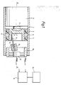
- Figure 1 shows a cylindrical housing 1 fixed in a projectile (not shown) with its axis AA aligned with the roll axis of the projectile body.
- An electrical motor 2 is fixed in the housing and the output shaft 3 of the motor is coupled to a cup shaped member 4 which is supported for rotation about axis AA by bearings 5 and of which the mouth faces away from the motor.
- motor 2 is driven so that the cup shaped member 4 rotates about axis AA at a mean rate (W + Wr) where W is the rate of rotation of the member relative to the projectile while Wr is the roll of the projectile.
- an elongate spring leaf 8 for example by having this one end engaged in a small slot shaped hole 9 formed here.
- the leaf 8 extends, with a shallow inward inclination relative to axis AA, along and then beyond wall 6 so that its other or outer end, to which there is fixed a mass 10, lies outside of the cup shaped member and, at least initially, is nearer to axis AA than the fixed inner end of the leaf while still being spaced from that axis.
- the thickness of the leaf i.e. its thinnest dimension, is in the direction generally radial to axis AA.
- a capacitor Fixed to the end of the housing near mass 10 is a capacitor formed by an outer cylindrical electrode 13 and an inner or central electrode 12.
- the mass 10 extends to within the space inside electrode 13 and adjacent electrode 12 so as to form, with the plates 12 and 13, a capacitive transducer through which energy can be imparted to the mass 10 to induce it to vibrate resonantly through a small amplitude back and forth radially with respect to axis AA and which also generates a signal indicative of that vibration.
- the drive energy is supplied and the vibration indicative signal is received by a drive and measuring circuit 14.
- the leaf in response to centrifugal force generated as the mass 10 rotates with member 4 about axis AA, the leaf is able to deflect outwards from the axis as shown by the dashed outline in the figure, the degree of deflection being dependent upon the rate of the rotation.
- the width of the spring leaf is substantially greater than its thickness so that the mass 10 tends to always vibrate and deflect in planes containing axis AA.
- the circuit 14 can integrate the rate signal supplied by the capacitance transducer to produce a continuously updated roll position signal.
- the sensor 15 could comprise a rate sensor which becomes active during this phase to sense the ballistic plane, this then being used as the datum for use by circuit 14 during subsequent flight phases.
- an inductive transducer (not shown) could be provided in the housing 1, the capacitive transducer being used to form the rotation rate indicative signal and the inductive transducer being used to impulse the mass 10 and maintain it vibrating.
- the capacitive transducer could be discarded and a suitable inductive transducer alone could carry out both functions.
- One or more abutments could be provided in housing 1, perhaps fixed to the member 4, to prevent the mass 10 from deflecting through too large an amount radially with respect to axis AA and/or laterally in response to any shock and over-range forces experienced by the device.
- axis AA should be coincident with the roll axis of the projectile body. An offset between these two axes will result in a cyclic variation of the roll rate signal which could be allowed for in the circuit 14. Similarly, though preferred, it is not essential that axis AA should be precisely parallel to the projectile roll axis.
- the rate indicative signal should not be influenced too greatly by fore and aft acceleration. pitch and yaw rotation, or lateral acceleration of the projectile.
- pitch and yaw rotation, or lateral acceleration of the projectile it is preferred that the inclination of the spring leaf 8 with respect to the fore and after projectile axis (axis AA in this case) should be comparatively small throughout its working range of movement radial to axis AA.
- the speed of motor 2 i.e. the rotation rate W of the cup shaped member and the spring leaf relative to the projectile body, should be substantially greater than the expected maximum roll rate of the projectile.
- W should be much greater than Wr because of the good effect this has on the linearity of the sensor as will be shown subsequently herein.
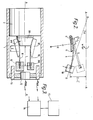
- Figure 2 shows part of the member 4, the curved surface defining member 11, the spring leaf 8 and the mass 10 all rotating about axis AA at a mean rate W + Wr so that, in response to centrifugal force, the mass 10 is deflected away from axis AA to bring a part of the spring leaf 8 into contact with the surface of member 11.
- This surface is a simple circular arc of radius R while the cross-section of leaf 8 is constant throughout its length.
- the initial, undeflected positions of leaf 8 and mass 10 are shown by the dashed outline.
- the leaf from the point where it emerges from fixing hole 9 to where it is attached to mass 10, has a length L and an initial portion X of this length has come into contact with member 11.
- the mass 10 has a mass value M and is at distance D from axis AA. From this position, a further incremental movement y of the mass takes place along a direction perpendicular to line BB at angle 0 ⁇ to axis AA.
- the force applied to the surface of member 11 at any position along the initial portion X of the spring leaf is counterbalanced by an equal and opposite reaction force applied by the surface to the spring leaf.
- K/M should be greater than (W + Wr)2 Cos2 0 ⁇ (which implies that the spring leaf should have a relatively high stiffness).
- the spring leaf 8 may be made of precipitation hardened berylium copper and have a length L of 0.75", a width b of 0.141" and a thickness d of 0.042", while the mass 10 is 7.5gms, the distance between the mass and axis AA when the leaf is undeflected is 0.124", the surface of member 11 is circularly curved with a radius R of 3.185", and the speed of motor 2, i.e. W/2II, is 175rps.
- the circuit 14 may incorporate a simple counter arranged to count cycles of the signal received from the sensor minus twice the rotation rate of the motor 2, i.e. to count W res /2II - W/II so that the content of the counter increases by ten for each revolution of the projectile and, over the given range of roll rates, the largest cumulative error in the roll position indication will be within a bandwidth of ⁇ 17° per second of recording time. This could be improved by further optimisation of the design and/or by trimming the built sensor, e.g. by trimming the mass 10 using laser beam machining apparatus.
- W res 2 (K/M) - (W + Wr)2 Cos2 0 ⁇ it will be appreciated that if (K/M) is proportional to (W + Wr)2 Cos2 0 ⁇ , then W res becomes proportional to (W + Wr). In developments (not shown) of the described and illustrated sensor, this is done by either or both of giving the spring leaf 8 a cross-sectional shape which is not constant throughout its length and making the surface of member 11 a complex curve rather than a simple circular arc.
- a cylindrical housing 1 with a motor 2 arranged so that the axes AA or the motor shaft and of the housing are aligned with the roll axis of the projectile (not shown).
- the motor 2 is provided with a relatively large diameter shaft 33 which has a curved inwards taper in the direction towards its end, i.e. away from the motor.
- the fixed end of the leaf spring 8, along with a fixed end of a second leaf spring 38 which is positioned diammetrically opposite spring 8, are clamped against the tapered part of the shaft 33 by respective profile defining members 311 which in turn are fixed to the shaft, say by screws (not shown).
- a clamp ring (not shown) which is such that in sectional elevation, at least the inner surfaces of its wall have the same shape as the surfaces of the members 311, i.e. so it is exactly equivalent to members 311 but simply extends right around the end of the shaft.
- a mass 310 At the free end of the leaf spring 38 is fixed a mass 310 which has the function simply of balancing the structure. Items 12, 13, 14 and 15 in Figure 3 are identical in construction and function to the like numbered elements of Figure 1.
- the mass 10 and spring leaf 8 could be replaced by a silicon chip which has been chemically etched to define a vibratory beam thereon, i.e. so that the beam is made of silicon, which, by virtue of having a support surface formed adjacent the beam (i.e. so as to act in the same way as the support formed by member 11 in Figure 1 or members 311 in Figure 3) or by virtue of being so shaped that its stiffness changes in any case with deflection of the beam, vibrates at a resonant frequency dependent upon the centrifugal force applied to it.
- the spring leaf 8 may be made of silicon cut from a single crystal wafer such that the beam width, b , and the beam axis lie in the 011 plane of the crystal and have a length L of 0.70", a width b of 0.125" and a thickness d of 0.0171", while the mass 10 is 0.1277 gms, the distance between the mass centre and axis AA when the leaf is undeflected is 0.276" and the speed of motor 2, i.e. W / 2II , is 175 rps.
- member 11 is also made of silicon and its surface is circularly curved with a radius R of 9.216".
- the circuit 14 may incorporate a simple counter arranged to count, in this example, cycles of the signal received from the sensor at a rate of two per cycle, minus ten times the rotation rate of the motor 2, i.e. to count W res - 5 x W , so that the content of the counter increases by forty for each revolution of the projectile and, over the given range of roll rates, the cumulative error in the roll position indication will then by zero at 15 rps rising to 12° per second of recording time at 12.5 rps and rising to 35° per second of recording time at 10 rps.
- these error figures can be reduced to a small fraction of the cumulative values here listed.
- a particular merit of ceramic silicon as the beam and support medium is its low change of Youngs Modulus with temperature, i.e. 30 parts per million per °C, and its low coefficient of expansion, i.e. 4.2 parts per million per °C, hence in this silicon embodiment example the cumulative error in roll rate per second of recording time is of order one degree per 10°C of temperature change.
- each of these members could be replaced by a pre-flexed secondary beam as shown in Figures 5 and 6.
- a vibratory beam 8 and integral mass 10 are cut from a silicon wafer as described earlier, the inner or fixed end of the beam being widened out to define a fixture land 50.
- a secondary beam 51 having fixture lands 52 at its two ends is also cut from a silicon wafer.
- the land 50 and one of the lands 52 are fused together in zones 53 towards the two sides of each land and also in the zone 54 just where the free length of the beam 8 is to start, this zone 54 being carefully positioned so as to achieve the desired free length.
- the composite beam is then fixed to an appropriate support sub-structure (not shown) which is in turn mounted to a rotary member (not shown), for example an appropriately adapted version of the cup-shaped member 4 or shaft 33, by fusing or bonding appropriate faces of the fixture lands 50 and/or 52 to the sub-structure, the secondary beam meanwhile being flexed so that it takes up it perfect curved shape and is then retained in that shape by the fixing of its two ends.
- the profile of the member 11 and 311 may be preferred for the profile of the member 11 and 311 not to comprise a uniformly circular curve.
- This can be achieved in relation to the use of the secondary beam of Figures 5 and 6 by making the secondary beam with a cross-sectional shape which is not constant throughout its flexure length, i.e. so that when it is flexed and its two ends fixed, it will assume a non-uniformly curved shape.
- the secondary beam could remain uniformly shaped but, instead of applying a simple 'perfect' bending couple to it, some more complex flexing load could be applied.
- an appropriate piece of silicon can be etched so as to form a structure (not shown) which incorporates a vibratory beam and mass and, in addition, an offset or inclined support strut or tie-bar coupled to the beam and pre-strained so as to make the vibration frequency of the structure as a whole dependent upon the deflection amplitude of the beam and mass.
- the earlier described arrangements i.e. those using a support surface such as members 11 and 311 or secondary beam 51, are preferred because they may offer a greater amplitude of vibration frequency variation for a given degree of deflection taking into account the resistance to in-use fracture of the beam.
Landscapes
- Physics & Mathematics (AREA)
- General Physics & Mathematics (AREA)
- Engineering & Computer Science (AREA)
- Radar, Positioning & Navigation (AREA)
- Remote Sensing (AREA)
- Measurement Of Mechanical Vibrations Or Ultrasonic Waves (AREA)
- Gyroscopes (AREA)
- Electric Ovens (AREA)
Applications Claiming Priority (4)
| Application Number | Priority Date | Filing Date | Title |
|---|---|---|---|
| GB8723324 | 1987-10-05 | ||
| GB878723324A GB8723324D0 (en) | 1987-10-05 | 1987-10-05 | Roll rate sensor |
| GB888808451A GB8808451D0 (en) | 1988-04-11 | 1988-04-11 | Roll rate sensor |
| GB8808451 | 1988-04-11 |
Publications (2)
| Publication Number | Publication Date |
|---|---|
| EP0311357A2 true EP0311357A2 (de) | 1989-04-12 |
| EP0311357A3 EP0311357A3 (de) | 1991-05-02 |
Family
ID=26292830
Family Applications (1)
| Application Number | Title | Priority Date | Filing Date |
|---|---|---|---|
| EP88309241A Withdrawn EP0311357A3 (de) | 1987-10-05 | 1988-10-04 | Drehgeschwindigkeitssensor |
Country Status (2)
| Country | Link |
|---|---|
| US (1) | US5014555A (de) |
| EP (1) | EP0311357A3 (de) |
Families Citing this family (4)
| Publication number | Priority date | Publication date | Assignee | Title |
|---|---|---|---|---|
| US6293150B1 (en) * | 1999-12-02 | 2001-09-25 | Precision Control Design | Motion sensor and method of making same |
| JP4359757B2 (ja) * | 2003-09-17 | 2009-11-04 | ソニー株式会社 | 情報表示装置 |
| RU2753983C1 (ru) * | 2020-12-29 | 2021-08-25 | Федеральное государственное бюджетное образовательное учреждение высшего образования "Алтайский государственный аграрный университет" (ФГБОУ ВО Алтайский ГАУ) | Способ автоматической настройки резонансных режимов колебаний вибрационной машины с приводом от асинхронного двигателя |
| CN119146940B (zh) * | 2024-09-27 | 2025-07-18 | 东华理工大学 | 一种用于丹霞地貌的测绘尺 |
Family Cites Families (9)
| Publication number | Priority date | Publication date | Assignee | Title |
|---|---|---|---|---|
| DE882323C (de) * | 1942-02-22 | 1953-07-09 | Aeg | Zentrifugalgeschwindigkeitsmesser oder -regler |
| GB741445A (en) * | 1953-06-18 | 1955-12-07 | Murdo Mackenzie | Apparatus for determining angular displacements of bodies |
| FR1522531A (fr) * | 1967-03-17 | 1968-04-26 | Thomson Houston Comp Francaise | Perfectionnements aux dispositifs de mesure de l'accélération de la pesanteur |
| US3877313A (en) * | 1973-07-23 | 1975-04-15 | Singer Co | Electrostatic accelerometer |
| US4222272A (en) * | 1978-03-27 | 1980-09-16 | Sanders Associates, Inc. | Processor for an inertial measurement unit |
| US4197478A (en) * | 1979-01-25 | 1980-04-08 | Southwest Research Institute | Electronically tunable resonant accelerometer |
| US4479385A (en) * | 1982-09-23 | 1984-10-30 | The United States Of America As Represented By The Department Of Energy | Double resonator cantilever accelerometer |
| US4848158A (en) * | 1983-03-31 | 1989-07-18 | Honeywell Inc. | Single-axis centrifugal rate sensor |
| US4718275A (en) * | 1986-06-27 | 1988-01-12 | Sundstrand Data Control, Inc. | Accelerometer with floating beam temperature compensation |
-
1988
- 1988-10-04 US US07/253,257 patent/US5014555A/en not_active Expired - Fee Related
- 1988-10-04 EP EP88309241A patent/EP0311357A3/de not_active Withdrawn
Also Published As
| Publication number | Publication date |
|---|---|
| US5014555A (en) | 1991-05-14 |
| EP0311357A3 (de) | 1991-05-02 |
Similar Documents
| Publication | Publication Date | Title |
|---|---|---|
| KR100327481B1 (ko) | 마이크로 자이로스코프 | |
| US4654663A (en) | Angular rate sensor system | |
| JP4577671B2 (ja) | 角速度測定のための構成 | |
| EP1415127B1 (de) | Isoliertes schwingungsgyroskop | |
| US6155115A (en) | Vibratory angular rate sensor | |
| US5505084A (en) | Micromechanical tuning fork angular rate sensor | |
| US5392650A (en) | Micromachined accelerometer gyroscope | |
| US5767405A (en) | Comb-drive micromechanical tuning fork gyroscope with piezoelectric readout | |
| US4381672A (en) | Vibrating beam rotation sensor | |
| US6860151B2 (en) | Methods and systems for controlling movement within MEMS structures | |
| US5430342A (en) | Single bar type vibrating element angular rate sensor system | |
| GB2158579A (en) | Angular rate sensor system | |
| US6910379B2 (en) | Out-of-plane compensation suspension for an accelerometer | |
| CA1129685A (en) | Flexure assembly for a dynamically tuned gyroscope | |
| CN101231303A (zh) | 加速度传感器 | |
| US3680391A (en) | Bell gyro and method of making same | |
| US4019391A (en) | Vibratory gyroscope | |
| CN111912399B (zh) | 一种改进比例因子的微型陀螺仪敏感单元及陀螺仪 | |
| EP0311357A2 (de) | Drehgeschwindigkeitssensor | |
| EP0273048A4 (en) | Translational accelerometer and accelerometer assembly method | |
| Ljung et al. | Micromachined two input axis angular rate sensor | |
| US4207668A (en) | Method of manufacturing a flexure suspension assembly | |
| Warren | Electrostatically Force‐Balanced Silicon Accelerometer | |
| KR100442823B1 (ko) | 마이크로자이로스코프 | |
| US5533394A (en) | Ferroelectric thin film travelling wave rotation sensor |
Legal Events
| Date | Code | Title | Description |
|---|---|---|---|
| PUAI | Public reference made under article 153(3) epc to a published international application that has entered the european phase |
Free format text: ORIGINAL CODE: 0009012 |
|
| 17P | Request for examination filed |
Effective date: 19881017 |
|
| AK | Designated contracting states |
Kind code of ref document: A2 Designated state(s): DE FR GB |
|
| PUAL | Search report despatched |
Free format text: ORIGINAL CODE: 0009013 |
|
| PUAF | Information related to the publication of a search report (a3 document) modified or deleted |
Free format text: ORIGINAL CODE: 0009199SEPU |
|
| AK | Designated contracting states |
Kind code of ref document: A3 Designated state(s): DE FR GB |
|
| D17D | Deferred search report published (deleted) | ||
| PUAL | Search report despatched |
Free format text: ORIGINAL CODE: 0009013 |
|
| AK | Designated contracting states |
Kind code of ref document: A3 Designated state(s): DE FR GB |
|
| 17Q | First examination report despatched |
Effective date: 19920512 |
|
| RAP3 | Party data changed (applicant data changed or rights of an application transferred) |
Owner name: BRITISH AEROSPACE PUBLIC LIMITED COMPANY |
|
| STAA | Information on the status of an ep patent application or granted ep patent |
Free format text: STATUS: THE APPLICATION IS DEEMED TO BE WITHDRAWN |
|
| 18D | Application deemed to be withdrawn |
Effective date: 19920929 |