EP0311422A1 - Verfahren zum Bohren einer Gesteinsschicht - Google Patents
Verfahren zum Bohren einer Gesteinsschicht Download PDFInfo
- Publication number
- EP0311422A1 EP0311422A1 EP88309371A EP88309371A EP0311422A1 EP 0311422 A1 EP0311422 A1 EP 0311422A1 EP 88309371 A EP88309371 A EP 88309371A EP 88309371 A EP88309371 A EP 88309371A EP 0311422 A1 EP0311422 A1 EP 0311422A1
- Authority
- EP
- European Patent Office
- Prior art keywords
- substrate
- core
- compacts
- array
- abrasive
- Prior art date
- Legal status (The legal status is an assumption and is not a legal conclusion. Google has not performed a legal analysis and makes no representation as to the accuracy of the status listed.)
- Withdrawn
Links
- 239000000758 substrate Substances 0.000 title claims abstract description 18
- 238000005553 drilling Methods 0.000 title claims abstract description 12
- 238000000034 method Methods 0.000 title claims abstract description 11
- 238000003491 array Methods 0.000 claims abstract description 10
- 239000011435 rock Substances 0.000 claims abstract description 8
- 239000011044 quartzite Substances 0.000 abstract description 4
- 239000010432 diamond Substances 0.000 description 17
- 229910003460 diamond Inorganic materials 0.000 description 17
- 239000002245 particle Substances 0.000 description 5
- 229910000906 Bronze Inorganic materials 0.000 description 2
- 239000010974 bronze Substances 0.000 description 2
- KUNSUQLRTQLHQQ-UHFFFAOYSA-N copper tin Chemical compound [Cu].[Sn] KUNSUQLRTQLHQQ-UHFFFAOYSA-N 0.000 description 2
- 239000000463 material Substances 0.000 description 2
- 239000011159 matrix material Substances 0.000 description 2
- 239000002184 metal Substances 0.000 description 2
- 229910052751 metal Inorganic materials 0.000 description 2
- 238000005065 mining Methods 0.000 description 2
- 229910052710 silicon Inorganic materials 0.000 description 2
- 239000010703 silicon Substances 0.000 description 2
- 229910052582 BN Inorganic materials 0.000 description 1
- PZNSFCLAULLKQX-UHFFFAOYSA-N Boron nitride Chemical compound N#B PZNSFCLAULLKQX-UHFFFAOYSA-N 0.000 description 1
- 229910000831 Steel Inorganic materials 0.000 description 1
- 239000003082 abrasive agent Substances 0.000 description 1
- 230000015572 biosynthetic process Effects 0.000 description 1
- 239000003054 catalyst Substances 0.000 description 1
- 230000001427 coherent effect Effects 0.000 description 1
- 239000000110 cooling liquid Substances 0.000 description 1
- 230000000694 effects Effects 0.000 description 1
- 238000011010 flushing procedure Methods 0.000 description 1
- 238000005755 formation reaction Methods 0.000 description 1
- PCHJSUWPFVWCPO-UHFFFAOYSA-N gold Chemical compound [Au] PCHJSUWPFVWCPO-UHFFFAOYSA-N 0.000 description 1
- 239000010931 gold Substances 0.000 description 1
- 229910052737 gold Inorganic materials 0.000 description 1
- 239000010438 granite Substances 0.000 description 1
- 230000002452 interceptive effect Effects 0.000 description 1
- 239000007788 liquid Substances 0.000 description 1
- 230000035515 penetration Effects 0.000 description 1
- 239000010453 quartz Substances 0.000 description 1
- HBMJWWWQQXIZIP-UHFFFAOYSA-N silicon carbide Chemical compound [Si+]#[C-] HBMJWWWQQXIZIP-UHFFFAOYSA-N 0.000 description 1
- 229910010271 silicon carbide Inorganic materials 0.000 description 1
- VYPSYNLAJGMNEJ-UHFFFAOYSA-N silicon dioxide Inorganic materials O=[Si]=O VYPSYNLAJGMNEJ-UHFFFAOYSA-N 0.000 description 1
- 239000007787 solid Substances 0.000 description 1
- 239000010959 steel Substances 0.000 description 1
Images
Classifications
-
- B—PERFORMING OPERATIONS; TRANSPORTING
- B28—WORKING CEMENT, CLAY, OR STONE
- B28D—WORKING STONE OR STONE-LIKE MATERIALS
- B28D1/00—Working stone or stone-like materials, e.g. brick, concrete or glass, not provided for elsewhere; Machines, devices, tools therefor
- B28D1/02—Working stone or stone-like materials, e.g. brick, concrete or glass, not provided for elsewhere; Machines, devices, tools therefor by sawing
- B28D1/04—Working stone or stone-like materials, e.g. brick, concrete or glass, not provided for elsewhere; Machines, devices, tools therefor by sawing with circular or cylindrical saw-blades or saw-discs
- B28D1/041—Working stone or stone-like materials, e.g. brick, concrete or glass, not provided for elsewhere; Machines, devices, tools therefor by sawing with circular or cylindrical saw-blades or saw-discs with cylinder saws, e.g. trepanning; saw cylinders, e.g. having their cutting rim equipped with abrasive particles
-
- E—FIXED CONSTRUCTIONS
- E21—EARTH OR ROCK DRILLING; MINING
- E21B—EARTH OR ROCK DRILLING; OBTAINING OIL, GAS, WATER, SOLUBLE OR MELTABLE MATERIALS OR A SLURRY OF MINERALS FROM WELLS
- E21B10/00—Drill bits
- E21B10/46—Drill bits characterised by wear resisting parts, e.g. diamond inserts
- E21B10/48—Drill bits characterised by wear resisting parts, e.g. diamond inserts the bit being of core type
Definitions
- This invention relates to a method of drilling a substrate.
- Rotary drills comprise a rotatable core having one end threaded for engagement in the drill and a working portion or cutting face at the other end.
- the working portion comprises a plurality of cutting elements firmly held in a suitable bonding matrix.
- the bonding matrix is usually a metal such as bronze.
- the cutting elements may be made of a variety of hard material such as diamond, cemented carbide and abrasive compacts.
- Abrasive compacts consist essentially of a mass of abrasive particles present in an amount of at least 70%, preferably 80 to 90%, by volume of the compact bonded into a hard conglomerate.
- Compacts are polycrystalline masses containing a substantial amount of direct particle-to-particle bonding.
- the abrasive particles of compacts are invariably ultra-hard abrasives such as diamond and cubic boron nitride.
- Diamond abrasive compacts which have a second phase containing a diamond catalyst tend to be thermally sensitive and degrade when exposed to temperatures above 700°C.
- Diamond abrasive compacts which are thermally stable at such temperatures are now known in the art. Examples of such compacts are described in United States Patent Specification No. 4,534,773 and British Patent Specification No. 2,158,086.
- Thermally stable diamond compacts have been commercially available for over three years and have, in conjunction with other thermally sensitive diamond compacts, become an established and integral part of the drilling and mining industry.
- the thermally sensitive diamond compacts have shown limitations in the drilling of harder materials such as granites.
- a method of drilling a substrate which contains hard rock having a compressive strength of at least 240 MPa including the steps of providing a rotary drill having a rotatable core mounted therein, the rotatable core comprising a working end provided with a plurality of abrasive compacts mounted therein and presenting cutting points for the working end, the abrasive compacts being arranged in a series of spaced arrays radiating out from an inner circle to an outer circle, rotating the core against the substrate in a direction such that the leading cutting point of each array is provided by a compact located in the outermost position of the array, and advancing the rotating core into the substrate.
- the abrasive compact may be any known in the art, but is preferably a thermally stable diamond abrasive compact.
- Thermally stable diamond abrasive compacts are those compacts which are capable of withstanding a temperature of 1200°C and a vacuum of 10 ⁇ 4 Torr or better, or in an inert or reducing atmosphere without significant graphitisation of the diamond occurring. This characteristic of the compacts makes them thermally stable at temperatures exceeding 700°C in air.
- Examples of particularly suitable thermally stable diamond abrasive compacts are those described in U.S. Patent Specification No. 4,534,773 and British Patent Specification No. 2,158,086.
- the abrasive compacts may be of any suitable shape, e.g. cube, rectangle, triangle or hexagon.
- the cutting point is preferably provided by the apex of a triangular shaped cutting face of the compact which protrudes from the surface in which it is mounted.
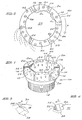
- FIG. 1 there is shown a rotatable core 10 suitable for mounting in a rotary drill.
- the core 10 has a working end 12 and a threaded end 14 for engagement in the rotary drill.
- the working end 12 is right-circular cylindrical in shape having vertical sides 16, 16A and a substantially flat top 18.
- Embedded in the outer vertical side 16 are gauge stones 15.
- a series of grooves 20 are cut into the core and extend downwardly from the surface 18. These grooves allow cooling liquid which passes up the hollow centre 22 of the core, in use, to escape from the core.
- abrasive compacts 24 Partially embedded in the surface 18 of the cylinder are a number of diamond abrasive compacts 24. Each compact is so embedded in the surface 18 that it presents a upwardly projecting cutting point 26.
- the abrasive compact may be of any suitable shape. An example of the use of a cube-shaped abrasive compact is illustrated by Figure 3, while the use of a triangular shaped compact is illustrated by Figure 4. Referring first to Figure 3, the abrasive compact 24 is so embedded in the surface 18 that it presents an exposed triangular cutting surface 28. The apex 30 of the surface provides the cutting point 26 of the embodiment of Figure 1.
- the compact 24 is triangular-shaped and is so mounted in the surface 18 that it presents an exposed triangular cutting surface 32, the apex 34 of which provides the cutting point 26 of the embodiment of Figure 1.
- the triangular shaped compact 24 is provided with a backing support 36.
- the core 10 is made of a metal such as steel and the abrasive compacts 24 will be bonded therein using a suitable braze such as bronze.
- the abrasive compacts are preferably thermally stable diamond abrasive compacts produced by the method described in the British Patent Specification No. 2,158,086. These abrasive compacts comprise a mass of diamond particles present in an amount of 85% by volume of the compact, and a second phase present in an amount of 15% by volume of the compact. The mass of diamond particles contain a substantial amount of diamond-to-diamond bonding to form a coherent, skeletal mass, and the second phase contains silicon in the form of silicon and/or silicon carbide.
- the abrasive compacts 24 are arranged in a series of spaced arrays 40.
- Each array 40 radiates outward from the top of the edge 42 of the inner circular vertical side 16A to the top of the edge 44 of the outer circular vertical side 16.
- arrays containing three compacts alternate with arrays containing four compacts.
- the centre compact 46 of a three-array is staggered relative to its nearest centre compacts 48, 50 in the adjacent four-arrays. This staggered arrangement ensures that the entire distance between the inner circular edge 42 and the outer circular edge 44 is traversed by abrasive compacts, effective cutting is achieved.
- the arrays 40 each radiate in the same direction creating a spiral effect.
- the core 10 is rotated in the direction of the arrow A. This is important because it means that for each array the leading compact 52 is the outermost compact of each array.
- flushing liquid is pumped through the hollow centre 22 and escapes through the grooves 20 and past the working face 18. In so doing, it carries with it swarf.
- the swarf With the compacts arranged in the manner set out in Figures 1 and 2, the swarf is swept away from the cutting points in the manner indicated by the dotted lines in Figure 2. This swarf is swept away without contacting or damaging a compact immediately behind it.
- the rotatable core 10 is rotated at a high speed and contacted with the substrate to be drilled. Drilling is effected by advancing the core 10 into the substrate. It has been found that using a rotatable core as illustrated in the drawings and in the manner described above, produces very excellent drill penetration rates and tool lives when drilling reef quartzite and similar hard-to-drill formations. This is particularly so when the abrasive compact is a thermally stable abrasive compact of the type described in the above-mentioned British Patent Specification No. 2,158,086.
Landscapes
- Engineering & Computer Science (AREA)
- Mining & Mineral Resources (AREA)
- Mechanical Engineering (AREA)
- Life Sciences & Earth Sciences (AREA)
- Geology (AREA)
- Physics & Mathematics (AREA)
- Environmental & Geological Engineering (AREA)
- Fluid Mechanics (AREA)
- General Life Sciences & Earth Sciences (AREA)
- Geochemistry & Mineralogy (AREA)
- Processing Of Stones Or Stones Resemblance Materials (AREA)
Applications Claiming Priority (2)
| Application Number | Priority Date | Filing Date | Title |
|---|---|---|---|
| ZA877569 | 1987-10-08 | ||
| ZA877569 | 1987-10-08 |
Publications (1)
| Publication Number | Publication Date |
|---|---|
| EP0311422A1 true EP0311422A1 (de) | 1989-04-12 |
Family
ID=25579021
Family Applications (1)
| Application Number | Title | Priority Date | Filing Date |
|---|---|---|---|
| EP88309371A Withdrawn EP0311422A1 (de) | 1987-10-08 | 1988-10-07 | Verfahren zum Bohren einer Gesteinsschicht |
Country Status (2)
| Country | Link |
|---|---|
| EP (1) | EP0311422A1 (de) |
| AU (1) | AU2354988A (de) |
Cited By (9)
| Publication number | Priority date | Publication date | Assignee | Title |
|---|---|---|---|---|
| GB2353744A (en) * | 1999-09-02 | 2001-03-07 | Marcrist Holdings Ltd | Core cutting tool |
| EP1297928A1 (de) * | 2001-09-28 | 2003-04-02 | Ehwa Diamond Ind. Co., Ltd. | Diamantwerkzeug |
| EP1283936A4 (de) * | 2000-05-18 | 2004-04-14 | Commw Scient Ind Res Org | Schneidwerkzeug und verfahren zu dessen benutzung |
| WO2011020111A3 (en) * | 2009-08-14 | 2011-05-12 | Longyear Tm, Inc. | Diamond impregnated bit with aggressive face profile |
| WO2011037948A3 (en) * | 2009-09-22 | 2011-06-30 | Longyear Tm, Inc. | Impregnated cutting elements with large abrasive cutting media and methods of making and using the same |
| CN101481993B (zh) * | 2009-01-20 | 2011-08-24 | 中国科学院武汉岩土力学研究所 | 一种高尾矿坝超深钻探钻头装置 |
| US8657894B2 (en) | 2011-04-15 | 2014-02-25 | Longyear Tm, Inc. | Use of resonant mixing to produce impregnated bits |
| US10702975B2 (en) | 2015-01-12 | 2020-07-07 | Longyear Tm, Inc. | Drilling tools having matrices with carbide-forming alloys, and methods of making and using same |
| CN113622827A (zh) * | 2021-08-31 | 2021-11-09 | 中国地质大学(武汉) | 一种用于钻进裂隙硬岩层的金刚石钻头 |
Citations (2)
| Publication number | Priority date | Publication date | Assignee | Title |
|---|---|---|---|---|
| EP0117506A2 (de) * | 1983-02-24 | 1984-09-05 | Eastman Christensen Company | Schneidzahn und Drehbohrmeissel mit einem ganz hervorstehenden polykristallinen Diamantelement |
| EP0206737A1 (de) * | 1985-06-18 | 1986-12-30 | De Beers Industrial Diamond Division (Proprietary) Limited | Schleifwerkzeug |
-
1988
- 1988-10-07 EP EP88309371A patent/EP0311422A1/de not_active Withdrawn
- 1988-10-07 AU AU23549/88A patent/AU2354988A/en not_active Abandoned
Patent Citations (2)
| Publication number | Priority date | Publication date | Assignee | Title |
|---|---|---|---|---|
| EP0117506A2 (de) * | 1983-02-24 | 1984-09-05 | Eastman Christensen Company | Schneidzahn und Drehbohrmeissel mit einem ganz hervorstehenden polykristallinen Diamantelement |
| EP0206737A1 (de) * | 1985-06-18 | 1986-12-30 | De Beers Industrial Diamond Division (Proprietary) Limited | Schleifwerkzeug |
Non-Patent Citations (1)
| Title |
|---|
| WORLD OIL, vol. 200, no. 7, June 1985, pages 149-154, Houston, Texas, US; A. PARK: "Coring: Part 4 - bit considerations" * |
Cited By (21)
| Publication number | Priority date | Publication date | Assignee | Title |
|---|---|---|---|---|
| GB2353744A (en) * | 1999-09-02 | 2001-03-07 | Marcrist Holdings Ltd | Core cutting tool |
| EP1283936A4 (de) * | 2000-05-18 | 2004-04-14 | Commw Scient Ind Res Org | Schneidwerkzeug und verfahren zu dessen benutzung |
| US6868848B2 (en) | 2000-05-18 | 2005-03-22 | The Commonwealth Of Australia Commonwealth Scientific And Industrial Research Organization | Cutting tool and method of using same |
| CN100402795C (zh) * | 2000-05-18 | 2008-07-16 | 联邦科学及工业研究组织 | 切削工具及其使用方法 |
| EP1297928A1 (de) * | 2001-09-28 | 2003-04-02 | Ehwa Diamond Ind. Co., Ltd. | Diamantwerkzeug |
| CN101481993B (zh) * | 2009-01-20 | 2011-08-24 | 中国科学院武汉岩土力学研究所 | 一种高尾矿坝超深钻探钻头装置 |
| CN105041223A (zh) * | 2009-08-14 | 2015-11-11 | 长年Tm公司 | 具有冲击表面轮廓的孕镶金刚石钻头 |
| US9637980B2 (en) | 2009-08-14 | 2017-05-02 | Longyear Tm, Inc. | Diamond impregnated bit with aggressive face profile |
| CN102472082A (zh) * | 2009-08-14 | 2012-05-23 | 长年Tm公司 | 具有冲击表面轮廓的孕镶金刚石钻头 |
| CN105041223B (zh) * | 2009-08-14 | 2018-04-06 | 长年Tm公司 | 具有冲击表面轮廓的孕镶金刚石钻头 |
| EP2464809A4 (de) * | 2009-08-14 | 2017-05-24 | Longyear TM, Inc. | Diamantenimprägniertes stück mit aggressivem vorderseitenprofil |
| WO2011020111A3 (en) * | 2009-08-14 | 2011-05-12 | Longyear Tm, Inc. | Diamond impregnated bit with aggressive face profile |
| AU2010282270B2 (en) * | 2009-08-14 | 2015-02-19 | Boart Longyear Manufacturing And Distribution Inc. | Diamond impregnated bit with aggressive face profile |
| US9051786B2 (en) | 2009-08-14 | 2015-06-09 | Longyear Tm, Inc. | Diamond impregnated bit with aggressive face profile |
| CN102667049B (zh) * | 2009-09-22 | 2015-08-05 | 长年Tm公司 | 具有大磨切介质的孕镶切削元件及其制造和使用方法 |
| WO2011037948A3 (en) * | 2009-09-22 | 2011-06-30 | Longyear Tm, Inc. | Impregnated cutting elements with large abrasive cutting media and methods of making and using the same |
| US8590646B2 (en) | 2009-09-22 | 2013-11-26 | Longyear Tm, Inc. | Impregnated cutting elements with large abrasive cutting media and methods of making and using the same |
| CN102667049A (zh) * | 2009-09-22 | 2012-09-12 | 长年Tm公司 | 具有大磨切介质的孕镶切削元件及其制造和使用方法 |
| US8657894B2 (en) | 2011-04-15 | 2014-02-25 | Longyear Tm, Inc. | Use of resonant mixing to produce impregnated bits |
| US10702975B2 (en) | 2015-01-12 | 2020-07-07 | Longyear Tm, Inc. | Drilling tools having matrices with carbide-forming alloys, and methods of making and using same |
| CN113622827A (zh) * | 2021-08-31 | 2021-11-09 | 中国地质大学(武汉) | 一种用于钻进裂隙硬岩层的金刚石钻头 |
Also Published As
| Publication number | Publication date |
|---|---|
| AU2354988A (en) | 1989-04-13 |
Similar Documents
| Publication | Publication Date | Title |
|---|---|---|
| JP2510324B2 (ja) | 回転ドリル用の回転可能なクラウン及び基層穿孔方法 | |
| US4098362A (en) | Rotary drill bit and method for making same | |
| EP0214795B1 (de) | Werkzeugteil | |
| US7316279B2 (en) | Polycrystalline cutter with multiple cutting edges | |
| US4186628A (en) | Rotary drill bit and method for making same | |
| KR100329309B1 (ko) | 연마절삭공구및연마절삭방법 | |
| EP0604211B1 (de) | Kompositwerkzeug für Bohrkronen | |
| US5601477A (en) | Polycrystalline abrasive compact with honed edge | |
| US5669943A (en) | Cutting tools having textured cutting surface | |
| CN100402795C (zh) | 切削工具及其使用方法 | |
| US5979579A (en) | Polycrystalline diamond cutter with enhanced durability | |
| KR19990045410A (ko) | 다결정 다이아몬드 콤팩트 커터 | |
| US10711528B2 (en) | Diamond cutting elements for drill bits seeded with HCP crystalline material | |
| EP2852731A1 (de) | Schneidelemente für erdbohrwerkzeuge, erdbohrwerkzeuge mit solchen schneidelementen und zugehörige verfahren | |
| GB2147037A (en) | Tool component | |
| BR112012027627A2 (pt) | compactos de diamante policristalino, elementos cortantes e ferramentas de perfuração do solo incluindo esses compactos e métodos de formação desses compactos e ferramentas de perfuração do solo | |
| AU600501B2 (en) | Cutting element for a mining machine | |
| EP0311422A1 (de) | Verfahren zum Bohren einer Gesteinsschicht | |
| US5092310A (en) | Mining pick | |
| CA2892056C (en) | Fixed cutter drill bit cutter elements including hard cutting tables made from cvd synthetic diamonds | |
| EP0446765B1 (de) | Schneidanordnung mit Unterbrechungen für Bohrmeissel | |
| US5685769A (en) | Tool component | |
| EP1251239B1 (de) | Bohrmeissel mit PCD-Schneidelementen mit grossem Durchmesser | |
| EP1120541A1 (de) | Axialsymmetrische Schneidelement | |
| EP0206737B1 (de) | Schleifwerkzeug |
Legal Events
| Date | Code | Title | Description |
|---|---|---|---|
| PUAI | Public reference made under article 153(3) epc to a published international application that has entered the european phase |
Free format text: ORIGINAL CODE: 0009012 |
|
| AK | Designated contracting states |
Kind code of ref document: A1 Designated state(s): AT BE CH DE ES FR GB GR IT LI LU NL SE |
|
| STAA | Information on the status of an ep patent application or granted ep patent |
Free format text: STATUS: THE APPLICATION IS DEEMED TO BE WITHDRAWN |
|
| 18D | Application deemed to be withdrawn |
Effective date: 19891014 |