EP0311593A2 - Vorratszylinder zum Auspressen einer pastösen Masse - Google Patents
Vorratszylinder zum Auspressen einer pastösen Masse Download PDFInfo
- Publication number
- EP0311593A2 EP0311593A2 EP88890240A EP88890240A EP0311593A2 EP 0311593 A2 EP0311593 A2 EP 0311593A2 EP 88890240 A EP88890240 A EP 88890240A EP 88890240 A EP88890240 A EP 88890240A EP 0311593 A2 EP0311593 A2 EP 0311593A2
- Authority
- EP
- European Patent Office
- Prior art keywords
- cylinder
- storage cylinder
- closure plate
- supply cylinder
- pressure medium
- Prior art date
- Legal status (The legal status is an assumption and is not a legal conclusion. Google has not performed a legal analysis and makes no representation as to the accuracy of the status listed.)
- Granted
Links
Images

Classifications
-
- E—FIXED CONSTRUCTIONS
- E06—DOORS, WINDOWS, SHUTTERS, OR ROLLER BLINDS IN GENERAL; LADDERS
- E06B—FIXED OR MOVABLE CLOSURES FOR OPENINGS IN BUILDINGS, VEHICLES, FENCES OR LIKE ENCLOSURES IN GENERAL, e.g. DOORS, WINDOWS, BLINDS, GATES
- E06B3/00—Window sashes, door leaves, or like elements for closing wall or like openings; Layout of fixed or moving closures, e.g. windows in wall or like openings; Features of rigidly-mounted outer frames relating to the mounting of wing frames
- E06B3/66—Units comprising two or more parallel glass or like panes permanently secured together
- E06B3/673—Assembling the units
- E06B3/67304—Preparing rigid spacer members before assembly
- E06B3/67321—Covering spacer elements, e.g. with sealants
-
- B—PERFORMING OPERATIONS; TRANSPORTING
- B05—SPRAYING OR ATOMISING IN GENERAL; APPLYING FLUENT MATERIALS TO SURFACES, IN GENERAL
- B05C—APPARATUS FOR APPLYING FLUENT MATERIALS TO SURFACES, IN GENERAL
- B05C11/00—Component parts, details or accessories not specifically provided for in groups B05C1/00 - B05C9/00
- B05C11/10—Storage, supply or control of liquid or other fluent material; Recovery of excess liquid or other fluent material
- B05C11/1039—Recovery of excess liquid or other fluent material; Controlling means therefor
-
- B—PERFORMING OPERATIONS; TRANSPORTING
- B29—WORKING OF PLASTICS; WORKING OF SUBSTANCES IN A PLASTIC STATE IN GENERAL
- B29B—PREPARATION OR PRETREATMENT OF THE MATERIAL TO BE SHAPED; MAKING GRANULES OR PREFORMS; RECOVERY OF PLASTICS OR OTHER CONSTITUENTS OF WASTE MATERIAL CONTAINING PLASTICS
- B29B13/00—Conditioning or physical treatment of the material to be shaped
- B29B13/02—Conditioning or physical treatment of the material to be shaped by heating
- B29B13/022—Melting the material to be shaped
-
- B—PERFORMING OPERATIONS; TRANSPORTING
- B29—WORKING OF PLASTICS; WORKING OF SUBSTANCES IN A PLASTIC STATE IN GENERAL
- B29C—SHAPING OR JOINING OF PLASTICS; SHAPING OF MATERIAL IN A PLASTIC STATE, NOT OTHERWISE PROVIDED FOR; AFTER-TREATMENT OF THE SHAPED PRODUCTS, e.g. REPAIRING
- B29C43/00—Compression moulding, i.e. applying external pressure to flow the moulding material; Apparatus therefor
- B29C43/32—Component parts, details or accessories; Auxiliary operations
- B29C43/34—Feeding the material to the mould or the compression means
-
- B—PERFORMING OPERATIONS; TRANSPORTING
- B29—WORKING OF PLASTICS; WORKING OF SUBSTANCES IN A PLASTIC STATE IN GENERAL
- B29L—INDEXING SCHEME ASSOCIATED WITH SUBCLASS B29C, RELATING TO PARTICULAR ARTICLES
- B29L2031/00—Other particular articles
- B29L2031/26—Sealing devices, e.g. packaging for pistons or pipe joints
- B29L2031/265—Packings, Gaskets
-
- B—PERFORMING OPERATIONS; TRANSPORTING
- B29—WORKING OF PLASTICS; WORKING OF SUBSTANCES IN A PLASTIC STATE IN GENERAL
- B29L—INDEXING SCHEME ASSOCIATED WITH SUBCLASS B29C, RELATING TO PARTICULAR ARTICLES
- B29L2031/00—Other particular articles
- B29L2031/778—Windows
- B29L2031/7782—Glazing
-
- E—FIXED CONSTRUCTIONS
- E06—DOORS, WINDOWS, SHUTTERS, OR ROLLER BLINDS IN GENERAL; LADDERS
- E06B—FIXED OR MOVABLE CLOSURES FOR OPENINGS IN BUILDINGS, VEHICLES, FENCES OR LIKE ENCLOSURES IN GENERAL, e.g. DOORS, WINDOWS, BLINDS, GATES
- E06B3/00—Window sashes, door leaves, or like elements for closing wall or like openings; Layout of fixed or moving closures, e.g. windows in wall or like openings; Features of rigidly-mounted outer frames relating to the mounting of wing frames
- E06B3/66—Units comprising two or more parallel glass or like panes permanently secured together
- E06B3/673—Assembling the units
- E06B3/67339—Working the edges of already assembled units
- E06B3/67343—Filling or covering the edges with synthetic hardenable substances
- E06B3/67347—Filling or covering the edges with synthetic hardenable substances by extrusion techniques
Definitions
- the invention relates to a storage cylinder for pressing out a pasty mass, for example a storage cylinder for butyl rubber in devices for coating the side surfaces of spacer frames for insulating glass, the storage cylinder containing a piston that can be pressurized and a closure plate is provided on the pressing side, which can be detached from the jacket of the storage cylinder , and with a device assigned to the storage cylinder for clamping the storage cylinder and the closure plate.
- Such a storage cylinder is known for example from AT-B-365 550.
- the invention has for its object to develop the known storage cylinder in such a way that the ventilation can be carried out quickly and easily than before.
- the device for clamping the supply cylinder and the closure plate preferably has a pressure medium motor has a hydraulic cylinder which can be relieved for a short time via a valve in the return line for the pressure medium when the supply cylinder is supplied with the mass to be pressed and pressurized, so that the supply cylinder can be detached from the closure plate for a short time.
- the invention is based on the knowledge that when the supply cylinder is briefly released from its closure plate, only air escapes from the cylinder, since the pasty mass, because of its consistency and its inertia, escapes much more slowly than air from the gap between the cylinder and its closure plate when it is pressurized.
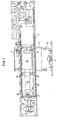
- the device shown in FIG. 1, known per se from AT-B-365 550, comprises a housing 1 which can be displaced in the vertical direction by means of a carriage 2 on a tripod 3.
- a foot switch 5 is provided at the base of the stand 3 for actuation.
- the housing 1 carries a console at the top with the switches or display devices necessary for operating the device.
- a conveyor belt 6 is provided around the housing 1, which can be set in motion by a drive motor 7 and to which a tensioning device 8 is supplied is arranged.
- the spacer profile frames to be coated are moved through between nozzles 9 and are coated on both sides with sealant or adhesive (eg butyl rubber).
- the sealant or adhesive preferably a butyl rubber
- a storage cylinder 10 is pressed out of this via a closure plate 11, which is optionally heated, to the nozzles 9.
- a hydraulic drive 13 is provided to act on the press cylinder 12, the piston of which presses the sealant or adhesive out of the supply cylinder 10 through the closure plate 11.
- the hydraulic drive 13 has, for example, a pneumatically actuated piston pump 14 and a reservoir 15 and is preferably constructed as described in AT-B-315 404.
- a self-tightening press unit is provided to seal the supply cylinder 10 from the closure plate 11.
- the clamping cylinder 16 pressing the supply cylinder 10 against the closure plate 11 is combined in the embodiment shown with the press cylinder 12, which acts on the piston of the supply cylinder 10, to form a printing unit.
- the piston rod of the tensioning cylinder 16 is supported against an abutment 17 of a subframe 18 which carries the closure plate 11 at its other end.
- sealant or adhesive is to be replenished in the supply cylinder 10
- the piston of the press cylinder 12 and then that of the clamping cylinder 16 are retrieved.
- the storage cylinder 10 is lifted off the closure plate 11 and can now be pivoted out of the housing 1 about the bearing 19.
- this is together with the cylinder unit, consisting of the clamping cylinder 16 and the press cylinder 12, in the original Position swung back.
- the clamping cylinder 16 and the press cylinder 12, which acts on the piston in the supply cylinder 10, are combined to form a double-acting cylinder unit (FIG. 2).
- the piston 30 of the clamping cylinder 16 and the piston 31 of the press cylinder 12 act in opposite directions. Characterized in that the piston 30 of the clamping cylinder 16 is smaller and both pistons are subjected to the same pressure, a higher force acts on the piston 31 of the press cylinder 12 and presses the supply cylinder 10, which is in the subframe 18 in a ring arranged between the bearings 19 is displaceably mounted against the closure plate 11.
- the supply cylinder 10 is sealed with respect to the closure plate 11. This construction also ensures that the clamping and press cylinders can only be acted upon together.
- the return lines 32 and 33 of the press cylinder 12 and the clamping cylinder 16 are equipped with a valve 34. Before the valve 34, the return line 32 opens into the return line 33.
- a throttle point 35 is also provided, which has two throttles 36 and 37 in the exemplary embodiment shown.
- valve 34 If the valve 34 is opened, the clamping cylinder 16 is relieved more quickly than the press cylinder 12, so that the supply cylinder 10 is lifted from its heating or sealing plate for a short time and air flows out of the supply cylinder 10 through the gap formed between the supply cylinder 10 and the sealing plate 11 can.
- valve 34 A time control is advantageously assigned to the valve 34.
- this valve which is preferably an electromagnetic valve, can only be opened for a short time even without great operator attention, if the supply cylinder 10 is to be vented.
- the closure plate 11 does not necessarily have to be heatable, in particular if the storage cylinder 10 itself is equipped with a heater.
- venting can be carried out after each loading process.
- the loading can also be done with the help of a dosing cylinder from a large storage cylinder.
Landscapes
- Engineering & Computer Science (AREA)
- Mechanical Engineering (AREA)
- Thermal Sciences (AREA)
- Civil Engineering (AREA)
- Structural Engineering (AREA)
- Physics & Mathematics (AREA)
- Coating Apparatus (AREA)
- Extrusion Moulding Of Plastics Or The Like (AREA)
- Noodles (AREA)
- Chair Legs, Seat Parts, And Backrests (AREA)
- Braking Systems And Boosters (AREA)
- Catching Or Destruction (AREA)
- Formation And Processing Of Food Products (AREA)
Abstract
Description
- Die Erfindung betrifft einen Vorratszylinder zum Auspressen einer pastösen Masse, beispielsweise ein Vorratszylinder für Butylkautschuk in Vorrichtungen zum Beschichten der Seitenflächen von Abstandhalterrahmen für Isolierglas, wobei der Vorratszylinder einen mit Druck beaufschlagbaren Kolben enthält und auspreßseitig eine Verschlußplatte vorgesehen ist, die vom Mantel des Vorratszylinders lösbar ist, und mit einer dem Vorratszylinder zugeordneten Vorrichtung zum Zusammenspannen von Vorratszylinder und Verschlußplatte.
- Ein derartiger Vorratszylinder ist beispielsweise aus der AT-B-365 550 bekannt.
- Wenn ein derartiger Vorratszylinder frisch mit auszupressender pastöser Masse beschickt wird, muß er entlüftet werden, was insbesondere bei Vorrichtungen zur Beschichtung von Abstandhalterrahmen für Isolierglas von erheblicher Bedeutung ist, damit in den auf den Abstandhalter beidseitig aufgebrachten Streifen aus Butylkautschuk keine Unterbrechungen entstehen. Bislang wurde die Entlüftung so vorgenommen, daß ein Entlüftungsventil so lange betätigt wurde, bis aus ihm nur mehr pastöse Masse (Butylkautschuk) austrat. Abgesehen davon, daß diese Art der Entlüftung viel Zeit in Anspruch nimmt, geht bei ihr auch eine nicht unerhebliche Menge der pastösen Masse verloren.
- Der Erfindung liegt die Aufgabe zugrunde, den bekannten Vorratszylinder in der Weise weiterzubilden, daß die Entlüftung rasch und einfacher als bisher ausgeführt werden kann.
- Erfindungsgemäß wird dies dadurch erreicht, daß die Vorrichtung zum Zusammenspannen von Vorratszylinder und Verschlußplatte einen Druckmittelmotor, vorzugsweise einen Hydraulikzylinder aufweist, der bei mit der auszupressenden Masse beschicktem und mit Druck beaufschlagtem Vorratszylinder über ein Ventil in der Rücklaufleitung für das Druckmedium kurzzeitig entlastbar ist, so daß der Vorratszylinder kurzzeitig von der Verschlußplatte lösbar ist.
- Die Erfindung geht von der Erkenntnis aus, daß beim kurzzeitigen Lösen des Vorratszylinders von seiner Verschlußplatte ausschließlich Luft aus dem Zylinder austritt, da die pastöse Masse wegen ihrer Konsistenz und ihrer Trägheit viel langsamer als Luft aus dem Spalt zwischen dem Zylinder und seiner Verschlußplatte austritt, auch wenn sie mit Druck beaufschlagt ist.
- Weitere Einzelheiten und Merkmale der Erfindung ergeben sich aus den Unteransprüchen und der nachfolgenden Beschreibung, in welcher auf die Zeichnungen Bezug genommen wird. Es zeigt
- Fig. 1 einen in eine Butylbeschichtungsvorrichtung für Abstandhalterrahmen eingebauten Vorratszylinder und
- Fig. 2 schematisch einen Vorratszylinder mit der ihm zugeordneten Verschlußplatte und den Leitungen für das Hydraulikmedium.
- Die in Fig. 1 gezeigte, an sich aus der AT-B-365 550 bekannte Vorrichtung umfaßt ein Gehäuse 1, das über einen Wagen 2 auf einem Stativ 3 in Höhenrichtung verschiebbar ist. Zur Betätigung ist am Fuß des Stativs 3 ein Fußschalter 5 vorgesehen. Das Gehäuse 1 trägt oben eine Konsole mit den für die Bedienung der Vorrichtung notwendigen Schaltern bzw. Anzeigegeräten.
- Um das Gehäuse 1 herumverlaufend ist ein Transportband 6 vorgesehen, das von einem Antriebsmotor 7 in Bewegung gesetzt werden kann und dem eine Spannvorrichtung 8 zuge ordnet ist. Mittels des Transportbandes 6 werden die zu beschichtenden Distanzprofilrahmen zwischen Düsen 9 hindurchbewegt und dabei beidseitig mit Dicht- bzw. Klebemittel (z.B. Butylkautschuk), beschichtet.
- Das Dicht- bzw. Klebemittel, vorzugsweise ein Butylkautschuk, ist in einem Vorratszylinder 10 enthalten und wird aus diesem über eine Verschlußplatte 11, die gegebenenfalls beheizt ist, zu den Düsen 9 gedrückt. Zur Beaufschlagung des Preßzylinders 12, dessen Kolben das Dicht- bzw. Klebemittel durch die Verschlußplatte 11 aus dem Vorratszylinder 10 herauspreßt, ist ein hydraulischer Antrieb 13 vorgesehen. Der hydraulische Antrieb 13 weist eine beispielsweise pneumatisch beaufschlagte Kolbenpumpe 14 und einen Vorratsbehälter 15 auf und ist vorzugsweise so wie in der AT-B-315 404 beschrieben, konstruiert.
- Zur Abdichtung des Vorratszylinders 10 gegenüber der Verschlußplatte 11 ist eine selbstspannende Preßeinheit vorgesehen. Der den Vorratszylinder 10 gegen die Verschlußplatte 11 drückende Spannzylinder 16 ist in der gezeigten Ausführungsform mit dem Preßzylinder 12, der den Kolben des Vorratszylinders 10 beaufschlagt, zu einer Druckeinheit kombiniert. Die Kolbenstange des Spannzylinders 16 stützt sich dabei gegen ein Widerlager 17 eines Hilfsrahmens 18, der an seinem andern Ende die Verschlußplatte 11 trägt.
- Soll in den Vorratszylinder 10 Dicht- bzw. Klebemittel nachgefüllt werden, so wird zunächst der Kolben des Preßzylinders 12 und dann der des Spannzylinders 16 zurückgeholt. Nach völliger Freistellung wird der Vorratszylinder 10 von der Verschlußplatte 11 abgehoben und kann nun um Lager 19 aus dem Gehäuse 1 herausgeschwenkt werden. Nach dem Einfüllen von Dicht- bzw. Klebemittel in den gut zugänglichen Vorratszylinder 10 wird dieser zusammen mit der Zylindereinheit, bestehend aus dem Spannzylinder 16 und dem Preßzylinder 12, in die ursprüngliche Lage zurückgeschwenkt.
- Der Spannzylinder 16 und der Preßzylinder 12, der den Kolben im Vorratszylinder 10 beaufschlagt, ist zu einer doppelt wirkenden Zylindereinheit (Fig. 2) zusammengefaßt. Dabei wirken der Kolben 30 des Spannzylinders 16 und der Kolben 31 des Preßzylinders 12 in entgegengesetze Richtungen. Dadurch, daß der Kolben 30 des Spannzylinders 16 kleiner ist und beide Kolben mit dem gleichen Druck beaufschlagt werden, wirkt auf den Kolben 31 des Preßzylinders 12 eine höhere Kraft und drückt den Vorratszylinder 10, der im Hilfsrahmen 18 in einem zwischen den Lagern 19 angeordneten Ring verschiebbar gelagert ist, gegen die Verschlußplatte 11. So wird der Vorratszylinder 10 gegenüber der Verschlußplatte 11 abgedichtet. Durch diese Konstruktion ist auch gewährleistet, daß Spann- und Preßzylinder immer nur gemeinsam beaufschlagt werden können.
- Wie aus Fig. 2 ersichtlich, sind die Rückleitungen 32 und 33 des Preßzylinders 12 und des Spannzylinders 16 mit einem Ventil 34 ausgestattet. Vor dem Ventil 34 mündet die Rückleitung 32 in die Rückleitung 33 ein. In der Rückleitung 33 des Preßzylinders 2 ist weiters eine Drosselstelle 35 vorgesehen, die im gezeigten Ausführungsbeispiel zwei Drosseln 36 und 37 aufweist.
- Wird das Ventil 34 geöffnet, dann entlastet der Spannzylinder 16 rascher als der Preßzylinder 12, so daß der Vorratszylinder 10 von seiner Heiz- bzw. Verschlußplatte kurzfristig abgehoben und durch den zwischen dem Vorratszylinder 10 und der Verschlußlatte 11 gebildeten Spalt Luft aus dem Vorratszylinder 10 ausströmen kann.
- Dem Ventil 34 ist mit Vorteil eine Zeitsteuerung zugeordnet. So kann dieses Ventil, das vorzugsweise ein Elektromagnetventil ist, auch ohne große Aufmerksamkeit der Bedienungsperson nur kurzfristig geöffnet werden, wenn der Vorratszylinder 10 entlüftet werden soll.
- Im Rahmen der Erfindung ist noch eine Ausführungsform denkbar, bei welcher der Spannzylinder der Verschlußplatte 11 zugeordnet ist.
- Die Verschlußplatte 11 muß nicht unbedingt beheizbar sein, insbesondere wenn der Vorratszylinder 10 selbst mit einer Heizung ausgestattet ist.
- Falls der Vorratszylinder 10 ein nur kleineres Volumen besitzt und über eine Leitung absatzweise mit pastöser Masse (Butylkautschuk) beschickt wird, dann kann nach jedem Beschickungsvorgang eine Entlüftung vorgenommen werden. Dies ist auch bei Vorrichtungen zum Beschichten von Abstandhalterrahmen mit Butylkautschuk denkbar, da jeweils nach dem Beschichten eines Abstandhalterrahmens oder aber auch nur eines Rahmenschenkels desselben Zeit für die Neubeschickung des Vorratszylinders mit Butylkautschuk und für die Entlüftung des Vorratszylinders zur Verfügung steht. Die Beschickung kann auch mit Hilfe eines Dosierzylinders aus einem großen Vorratszylinder erfolgen.
Claims (3)
Applications Claiming Priority (2)
| Application Number | Priority Date | Filing Date | Title |
|---|---|---|---|
| AT2535/87 | 1987-10-05 | ||
| AT0253587A AT393829B (de) | 1987-10-05 | 1987-10-05 | Vorratszylinder zum auspressen einer pastoesen masse |
Publications (3)
| Publication Number | Publication Date |
|---|---|
| EP0311593A2 true EP0311593A2 (de) | 1989-04-12 |
| EP0311593A3 EP0311593A3 (en) | 1989-07-26 |
| EP0311593B1 EP0311593B1 (de) | 1990-05-23 |
Family
ID=3536023
Family Applications (1)
| Application Number | Title | Priority Date | Filing Date |
|---|---|---|---|
| EP88890240A Expired - Lifetime EP0311593B1 (de) | 1987-10-05 | 1988-09-21 | Vorratszylinder zum Auspressen einer pastösen Masse |
Country Status (4)
| Country | Link |
|---|---|
| EP (1) | EP0311593B1 (de) |
| AT (2) | AT393829B (de) |
| DE (2) | DE8811618U1 (de) |
| ES (1) | ES2015617B3 (de) |
Cited By (4)
| Publication number | Priority date | Publication date | Assignee | Title |
|---|---|---|---|---|
| DE4009686A1 (de) * | 1990-03-26 | 1991-10-02 | Bayerische Motoren Werke Ag | Vorrichtung zum entleeren eines mit pastoesen medien gefuellten foliensackes |
| RU2345253C2 (ru) * | 2007-03-05 | 2009-01-27 | Государственное образовательное учреждение высшего профессионального образования СИБИРСКИЙ ГОСУДАРСТВЕННЫЙ ИНДУСТРИАЛЬНЫЙ УНИВЕРСИТЕТ | Гидродомкрат-усилитель |
| CN110605220A (zh) * | 2019-10-24 | 2019-12-24 | 苏州红杉自动化科技有限公司 | 一种单泵供料系统 |
| CN114161636A (zh) * | 2021-11-10 | 2022-03-11 | 浙江宏南精密工业有限公司 | 一种塑料制品快速成型装置 |
Families Citing this family (1)
| Publication number | Priority date | Publication date | Assignee | Title |
|---|---|---|---|---|
| AT398309B (de) * | 1989-11-13 | 1994-11-25 | Lisec Peter | Vorrichtung zum beschichten von abstandhalterrahmen |
Family Cites Families (4)
| Publication number | Priority date | Publication date | Assignee | Title |
|---|---|---|---|---|
| US3196597A (en) * | 1962-03-22 | 1965-07-27 | Itt | Tank-loading and de-aeration of viscous materials |
| US3523147A (en) * | 1967-09-28 | 1970-08-04 | Usm Corp | Plastication of thermoplastic materials |
| AT365550B (de) * | 1977-03-02 | 1982-01-25 | Lisec Peter | Vorrichtung zum beschichten von distanzprofilen fuer mehrscheiben-isolierglas mit dicht- bzw. klebemittel |
| US4632277A (en) * | 1984-07-19 | 1986-12-30 | Nordson Corporation | Bulk melter having drum hold-down device |
-
1987
- 1987-10-05 AT AT0253587A patent/AT393829B/de not_active IP Right Cessation
-
1988
- 1988-09-13 DE DE8811618U patent/DE8811618U1/de not_active Expired
- 1988-09-21 ES ES88890240T patent/ES2015617B3/es not_active Expired - Lifetime
- 1988-09-21 EP EP88890240A patent/EP0311593B1/de not_active Expired - Lifetime
- 1988-09-21 AT AT88890240T patent/ATE52961T1/de not_active IP Right Cessation
- 1988-09-21 DE DE8888890240T patent/DE3860161D1/de not_active Expired - Lifetime
Cited By (4)
| Publication number | Priority date | Publication date | Assignee | Title |
|---|---|---|---|---|
| DE4009686A1 (de) * | 1990-03-26 | 1991-10-02 | Bayerische Motoren Werke Ag | Vorrichtung zum entleeren eines mit pastoesen medien gefuellten foliensackes |
| RU2345253C2 (ru) * | 2007-03-05 | 2009-01-27 | Государственное образовательное учреждение высшего профессионального образования СИБИРСКИЙ ГОСУДАРСТВЕННЫЙ ИНДУСТРИАЛЬНЫЙ УНИВЕРСИТЕТ | Гидродомкрат-усилитель |
| CN110605220A (zh) * | 2019-10-24 | 2019-12-24 | 苏州红杉自动化科技有限公司 | 一种单泵供料系统 |
| CN114161636A (zh) * | 2021-11-10 | 2022-03-11 | 浙江宏南精密工业有限公司 | 一种塑料制品快速成型装置 |
Also Published As
| Publication number | Publication date |
|---|---|
| ATE52961T1 (de) | 1990-06-15 |
| DE3860161D1 (de) | 1990-06-28 |
| AT393829B (de) | 1991-12-27 |
| EP0311593A3 (en) | 1989-07-26 |
| DE8811618U1 (de) | 1988-10-27 |
| EP0311593B1 (de) | 1990-05-23 |
| ES2015617B3 (es) | 1990-09-01 |
| ATA253587A (de) | 1991-06-15 |
Similar Documents
| Publication | Publication Date | Title |
|---|---|---|
| DE2818337C2 (de) | Druckübersetzter hydropneumatischer | |
| DE1920184C3 (de) | Vorrichtung zum gleichzeitigen und gleichmäßigen Bewegen mehrerer, durch Druckmittel betriebener Arbeitszylinder | |
| DE2627160A1 (de) | Presse zum herstellen von tellern o.dgl. | |
| DE3329296C2 (de) | Verfahren und Einrichtung zum Dosieren von viskosen Stoffen, insbesondere Zweikomponenten-Kunststoffen | |
| EP0649019B1 (de) | Axial komprimierbare Einrichtung für die Chromatographie | |
| EP0311593B1 (de) | Vorratszylinder zum Auspressen einer pastösen Masse | |
| DE3506222C2 (de) | Vorrichtung zum Pressen von Sprengstoff-Formkörpern | |
| DE2557664A1 (de) | Hydraulisch oder mit pressluft antreibbare zylinder-kolben-einheit | |
| DD253179A5 (de) | Klebepresse zur ankleben von schuhsohlen an aufgeleisteten oberschuhen | |
| DE2141072C3 (de) | Hydraulische Strangpresse zum Auspressen plastischer und/oder pulverförmiger Stoffe | |
| DE4436407B4 (de) | Vorrichtung und Verfahren zum Schließen einer mehrteiligen Kammer einer Verpackungsmaschine | |
| DE898885C (de) | Hilfsvorrichtung fuer Tiefziehwerkzeuge | |
| DE19642437B4 (de) | Presse für die Formung von Teilen aus Pulverkeramik | |
| DE2602102C2 (de) | Strangpresse | |
| DE2833626A1 (de) | Kombinierte press- und stanzvorrichtung | |
| DD160894A5 (de) | Einrichtung fuer fluessigpressen | |
| DE2420428C3 (de) | Anlage zum isostatischen Pressen von keramischen Erzeugnissen aus pulverförmigen Massen | |
| DE3709204C1 (en) | Belt release device for a system for the vulcanisation of conveyor belts | |
| DE2854523A1 (de) | Strangpresse zum kontinuierlichen auspressen plastischer kohlemasse zu elektroden fuer elektrische oefen | |
| DE3214486A1 (de) | Verfahren und vorrichtung zur herstellung von zahnprothesen aus polymerisierbarem, injizierbarem und wenigstens zeitweise giessfaehigem kunststoff | |
| DD154368A5 (de) | Vorrichtung und verfahren zum biegen von zuschnitten fuer die herstellung von waren aus leder oder synthetischen werkstoffen | |
| DE1024911B (de) | Verfahren zum Betrieb von pneumatisch-hydraulischen Grubenstempeln | |
| DE2240674C3 (de) | Presse zum Herstellen keramischer Gegenstände | |
| DE1640535C (de) | Einrichtung zum Aufdrucken elektn scher Schaltungselemente auf Tragerkorper | |
| DE2517401B2 (de) | Presse zur Behandlung von Produkten unter hohem Druck |
Legal Events
| Date | Code | Title | Description |
|---|---|---|---|
| PUAI | Public reference made under article 153(3) epc to a published international application that has entered the european phase |
Free format text: ORIGINAL CODE: 0009012 |
|
| AK | Designated contracting states |
Kind code of ref document: A2 Designated state(s): AT BE CH DE ES FR GB GR IT LI LU NL SE |
|
| PUAL | Search report despatched |
Free format text: ORIGINAL CODE: 0009013 |
|
| RHK1 | Main classification (correction) |
Ipc: B29B 13/02 |
|
| AK | Designated contracting states |
Kind code of ref document: A3 Designated state(s): AT BE CH DE ES FR GB GR IT LI LU NL SE |
|
| 17P | Request for examination filed |
Effective date: 19890719 |
|
| 17Q | First examination report despatched |
Effective date: 19891102 |
|
| ITF | It: translation for a ep patent filed | ||
| GRAA | (expected) grant |
Free format text: ORIGINAL CODE: 0009210 |
|
| AK | Designated contracting states |
Kind code of ref document: B1 Designated state(s): AT BE CH DE ES FR GB GR IT LI LU NL SE |
|
| PG25 | Lapsed in a contracting state [announced via postgrant information from national office to epo] |
Ref country code: NL Effective date: 19900523 Ref country code: GR Free format text: LAPSE BECAUSE OF FAILURE TO SUBMIT A TRANSLATION OF THE DESCRIPTION OR TO PAY THE FEE WITHIN THE PRESCRIBED TIME-LIMIT Effective date: 19900523 |
|
| REF | Corresponds to: |
Ref document number: 52961 Country of ref document: AT Date of ref document: 19900615 Kind code of ref document: T |
|
| ET | Fr: translation filed | ||
| GBT | Gb: translation of ep patent filed (gb section 77(6)(a)/1977) | ||
| REF | Corresponds to: |
Ref document number: 3860161 Country of ref document: DE Date of ref document: 19900628 |
|
| PG25 | Lapsed in a contracting state [announced via postgrant information from national office to epo] |
Ref country code: SE Effective date: 19900922 |
|
| PG25 | Lapsed in a contracting state [announced via postgrant information from national office to epo] |
Ref country code: LU Free format text: LAPSE BECAUSE OF NON-PAYMENT OF DUE FEES Effective date: 19900930 Ref country code: BE Effective date: 19900930 |
|
| NLV1 | Nl: lapsed or annulled due to failure to fulfill the requirements of art. 29p and 29m of the patents act | ||
| PLBE | No opposition filed within time limit |
Free format text: ORIGINAL CODE: 0009261 |
|
| STAA | Information on the status of an ep patent application or granted ep patent |
Free format text: STATUS: NO OPPOSITION FILED WITHIN TIME LIMIT |
|
| BERE | Be: lapsed |
Owner name: LISEC PETER Effective date: 19900930 |
|
| 26N | No opposition filed | ||
| ITTA | It: last paid annual fee | ||
| EUG | Se: european patent has lapsed |
Ref document number: 88890240.0 Effective date: 19910527 |
|
| PGFP | Annual fee paid to national office [announced via postgrant information from national office to epo] |
Ref country code: ES Payment date: 19980903 Year of fee payment: 11 |
|
| PGFP | Annual fee paid to national office [announced via postgrant information from national office to epo] |
Ref country code: GB Payment date: 19980914 Year of fee payment: 11 |
|
| PGFP | Annual fee paid to national office [announced via postgrant information from national office to epo] |
Ref country code: FR Payment date: 19980917 Year of fee payment: 11 |
|
| PGFP | Annual fee paid to national office [announced via postgrant information from national office to epo] |
Ref country code: AT Payment date: 19980928 Year of fee payment: 11 |
|
| PGFP | Annual fee paid to national office [announced via postgrant information from national office to epo] |
Ref country code: DE Payment date: 19981119 Year of fee payment: 11 |
|
| PGFP | Annual fee paid to national office [announced via postgrant information from national office to epo] |
Ref country code: CH Payment date: 19981201 Year of fee payment: 11 |
|
| PG25 | Lapsed in a contracting state [announced via postgrant information from national office to epo] |
Ref country code: GB Free format text: LAPSE BECAUSE OF NON-PAYMENT OF DUE FEES Effective date: 19990921 Ref country code: AT Free format text: LAPSE BECAUSE OF NON-PAYMENT OF DUE FEES Effective date: 19990921 |
|
| PG25 | Lapsed in a contracting state [announced via postgrant information from national office to epo] |
Ref country code: ES Free format text: LAPSE BECAUSE OF NON-PAYMENT OF DUE FEES Effective date: 19990922 |
|
| PG25 | Lapsed in a contracting state [announced via postgrant information from national office to epo] |
Ref country code: LI Free format text: LAPSE BECAUSE OF NON-PAYMENT OF DUE FEES Effective date: 19990930 Ref country code: CH Free format text: LAPSE BECAUSE OF NON-PAYMENT OF DUE FEES Effective date: 19990930 |
|
| GBPC | Gb: european patent ceased through non-payment of renewal fee |
Effective date: 19990921 |
|
| REG | Reference to a national code |
Ref country code: CH Ref legal event code: PL |
|
| PG25 | Lapsed in a contracting state [announced via postgrant information from national office to epo] |
Ref country code: FR Free format text: LAPSE BECAUSE OF NON-PAYMENT OF DUE FEES Effective date: 20000531 |
|
| PG25 | Lapsed in a contracting state [announced via postgrant information from national office to epo] |
Ref country code: DE Free format text: LAPSE BECAUSE OF NON-PAYMENT OF DUE FEES Effective date: 20000701 |
|
| REG | Reference to a national code |
Ref country code: FR Ref legal event code: ST |
|
| REG | Reference to a national code |
Ref country code: ES Ref legal event code: FD2A Effective date: 20001013 |
|
| PG25 | Lapsed in a contracting state [announced via postgrant information from national office to epo] |
Ref country code: IT Free format text: LAPSE BECAUSE OF NON-PAYMENT OF DUE FEES;WARNING: LAPSES OF ITALIAN PATENTS WITH EFFECTIVE DATE BEFORE 2007 MAY HAVE OCCURRED AT ANY TIME BEFORE 2007. THE CORRECT EFFECTIVE DATE MAY BE DIFFERENT FROM THE ONE RECORDED. Effective date: 20050921 |