EP0311598A2 - Cartouche de robinet pour vanne à une voie - Google Patents
Cartouche de robinet pour vanne à une voie Download PDFInfo
- Publication number
- EP0311598A2 EP0311598A2 EP88890255A EP88890255A EP0311598A2 EP 0311598 A2 EP0311598 A2 EP 0311598A2 EP 88890255 A EP88890255 A EP 88890255A EP 88890255 A EP88890255 A EP 88890255A EP 0311598 A2 EP0311598 A2 EP 0311598A2
- Authority
- EP
- European Patent Office
- Prior art keywords
- cartridge according
- driver
- head piece
- sealing
- central part
- Prior art date
- Legal status (The legal status is an assumption and is not a legal conclusion. Google has not performed a legal analysis and makes no representation as to the accuracy of the status listed.)
- Granted
Links
- 238000007789 sealing Methods 0.000 claims abstract description 33
- 239000003566 sealing material Substances 0.000 claims abstract description 4
- 238000004519 manufacturing process Methods 0.000 claims description 3
- 238000002788 crimping Methods 0.000 claims 1
- XLYOFNOQVPJJNP-UHFFFAOYSA-N water Substances O XLYOFNOQVPJJNP-UHFFFAOYSA-N 0.000 description 5
- 230000002308 calcification Effects 0.000 description 3
- 230000007797 corrosion Effects 0.000 description 3
- 238000005260 corrosion Methods 0.000 description 3
- PNEYBMLMFCGWSK-UHFFFAOYSA-N aluminium oxide Inorganic materials [O-2].[O-2].[O-2].[Al+3].[Al+3] PNEYBMLMFCGWSK-UHFFFAOYSA-N 0.000 description 1
- 239000000919 ceramic Substances 0.000 description 1
- 229910052593 corundum Inorganic materials 0.000 description 1
- 239000004744 fabric Substances 0.000 description 1
- 238000009434 installation Methods 0.000 description 1
- 229910001845 yogo sapphire Inorganic materials 0.000 description 1
Images

Classifications
-
- F—MECHANICAL ENGINEERING; LIGHTING; HEATING; WEAPONS; BLASTING
- F16—ENGINEERING ELEMENTS AND UNITS; GENERAL MEASURES FOR PRODUCING AND MAINTAINING EFFECTIVE FUNCTIONING OF MACHINES OR INSTALLATIONS; THERMAL INSULATION IN GENERAL
- F16K—VALVES; TAPS; COCKS; ACTUATING-FLOATS; DEVICES FOR VENTING OR AERATING
- F16K1/00—Lift valves or globe valves, i.e. cut-off apparatus with closure members having at least a component of their opening and closing motion perpendicular to the closing faces
-
- F—MECHANICAL ENGINEERING; LIGHTING; HEATING; WEAPONS; BLASTING
- F16—ENGINEERING ELEMENTS AND UNITS; GENERAL MEASURES FOR PRODUCING AND MAINTAINING EFFECTIVE FUNCTIONING OF MACHINES OR INSTALLATIONS; THERMAL INSULATION IN GENERAL
- F16K—VALVES; TAPS; COCKS; ACTUATING-FLOATS; DEVICES FOR VENTING OR AERATING
- F16K3/00—Gate valves or sliding valves, i.e. cut-off apparatus with closing members having a sliding movement along the seat for opening and closing
- F16K3/02—Gate valves or sliding valves, i.e. cut-off apparatus with closing members having a sliding movement along the seat for opening and closing with flat sealing faces; Packings therefor
- F16K3/04—Gate valves or sliding valves, i.e. cut-off apparatus with closing members having a sliding movement along the seat for opening and closing with flat sealing faces; Packings therefor with pivoted closure members
- F16K3/06—Gate valves or sliding valves, i.e. cut-off apparatus with closing members having a sliding movement along the seat for opening and closing with flat sealing faces; Packings therefor with pivoted closure members in the form of closure plates arranged between supply and discharge passages
- F16K3/08—Gate valves or sliding valves, i.e. cut-off apparatus with closing members having a sliding movement along the seat for opening and closing with flat sealing faces; Packings therefor with pivoted closure members in the form of closure plates arranged between supply and discharge passages with circular plates rotatable around their centres
-
- F—MECHANICAL ENGINEERING; LIGHTING; HEATING; WEAPONS; BLASTING
- F16—ENGINEERING ELEMENTS AND UNITS; GENERAL MEASURES FOR PRODUCING AND MAINTAINING EFFECTIVE FUNCTIONING OF MACHINES OR INSTALLATIONS; THERMAL INSULATION IN GENERAL
- F16K—VALVES; TAPS; COCKS; ACTUATING-FLOATS; DEVICES FOR VENTING OR AERATING
- F16K27/00—Construction of housing; Use of materials therefor
- F16K27/04—Construction of housing; Use of materials therefor of sliding valves
- F16K27/044—Construction of housing; Use of materials therefor of sliding valves slide valves with flat obturating members
- F16K27/045—Construction of housing; Use of materials therefor of sliding valves slide valves with flat obturating members with pivotal obturating members
-
- F—MECHANICAL ENGINEERING; LIGHTING; HEATING; WEAPONS; BLASTING
- F16—ENGINEERING ELEMENTS AND UNITS; GENERAL MEASURES FOR PRODUCING AND MAINTAINING EFFECTIVE FUNCTIONING OF MACHINES OR INSTALLATIONS; THERMAL INSULATION IN GENERAL
- F16K—VALVES; TAPS; COCKS; ACTUATING-FLOATS; DEVICES FOR VENTING OR AERATING
- F16K5/00—Plug valves; Taps or cocks comprising only cut-off apparatus having at least one of the sealing faces shaped as a more or less complete surface of a solid of revolution, the opening and closing movement being predominantly rotary
- F16K5/04—Plug valves; Taps or cocks comprising only cut-off apparatus having at least one of the sealing faces shaped as a more or less complete surface of a solid of revolution, the opening and closing movement being predominantly rotary with plugs having cylindrical surfaces; Packings therefor
-
- F—MECHANICAL ENGINEERING; LIGHTING; HEATING; WEAPONS; BLASTING
- F16—ENGINEERING ELEMENTS AND UNITS; GENERAL MEASURES FOR PRODUCING AND MAINTAINING EFFECTIVE FUNCTIONING OF MACHINES OR INSTALLATIONS; THERMAL INSULATION IN GENERAL
- F16K—VALVES; TAPS; COCKS; ACTUATING-FLOATS; DEVICES FOR VENTING OR AERATING
- F16K5/00—Plug valves; Taps or cocks comprising only cut-off apparatus having at least one of the sealing faces shaped as a more or less complete surface of a solid of revolution, the opening and closing movement being predominantly rotary
- F16K5/08—Details
- F16K5/14—Special arrangements for separating the sealing faces or for pressing them together
- F16K5/18—Special arrangements for separating the sealing faces or for pressing them together for plugs with cylindrical surfaces
-
- Y—GENERAL TAGGING OF NEW TECHNOLOGICAL DEVELOPMENTS; GENERAL TAGGING OF CROSS-SECTIONAL TECHNOLOGIES SPANNING OVER SEVERAL SECTIONS OF THE IPC; TECHNICAL SUBJECTS COVERED BY FORMER USPC CROSS-REFERENCE ART COLLECTIONS [XRACs] AND DIGESTS
- Y10—TECHNICAL SUBJECTS COVERED BY FORMER USPC
- Y10T—TECHNICAL SUBJECTS COVERED BY FORMER US CLASSIFICATION
- Y10T137/00—Fluid handling
- Y10T137/7504—Removable valve head and seat unit
- Y10T137/7613—Threaded into valve casing
-
- Y—GENERAL TAGGING OF NEW TECHNOLOGICAL DEVELOPMENTS; GENERAL TAGGING OF CROSS-SECTIONAL TECHNOLOGIES SPANNING OVER SEVERAL SECTIONS OF THE IPC; TECHNICAL SUBJECTS COVERED BY FORMER USPC CROSS-REFERENCE ART COLLECTIONS [XRACs] AND DIGESTS
- Y10—TECHNICAL SUBJECTS COVERED BY FORMER USPC
- Y10T—TECHNICAL SUBJECTS COVERED BY FORMER US CLASSIFICATION
- Y10T137/00—Fluid handling
- Y10T137/794—With means for separating solid material from the fluid
- Y10T137/8122—Planar strainer normal to flow path
Definitions
- the invention relates to an upper part cartridge for a sanitary individual shut-off valve, consisting of a threaded head piece which can be sealed by means of an O-ring, a spindle, a movable sealing disk which is driven together with the spindle and has through openings, and a non-rotatably arranged through openings having sealing washer and a driver pin which passes through the head piece or a middle part, the fixed sealing washer and then the movable sealing washer and is connected at the lower end to a driver which engages in a recess in the movable sealing washer.
- the driver pin is welded to the driver at the lower end and the space between driver, driver pin and movable sealing washer is filled with sealing material, so that the driver pin can be pressed into the spindle at different depths depending on the manufacturing-related differences in thickness of the pair of disks, which is arranged with longitudinal axial play and so is displaceable accordingly, and that the spindle is arranged in a bearing bush.
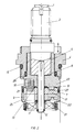
- FIG. 1 shows an embodiment of the invention and FIG. 2 shows another embodiment.
- FIG. 1 shows a section through an assembled upper part cartridge for a sanitary individual shut-off valve.
- the cartridge is mounted in an opening by means of the thread 26 and via the O-rings 14, 15 2 sealed.
- sealing disks 9 and 17 are provided, which are provided with openings 18, 19.
- the head piece 4, on which the thread 26 is provided, is located above the two sealing disks.
- the spindle 2 engages in the head piece, which in turn is connected to an actuating lever via the grip screw 1.
- the spindle 2 is pressed with a driver pin 12 which passes through the fixed sealing disk 17 and the movable sealing disk 9 and is laser-welded to a driver 21 at its lower end.
- This driver engages in a recess 22 of the movable disk 9, so that when the spindle 2 is moved via the driver pin 12 and the driver 21, the disk 9 is rotated.
- a fabric insert 16 or a sieve is arranged at the outlet opening from the sealing disks for noise reduction.
- the spindle 2 is mounted in a bearing bush 5 which has a bottom 6.
- This bearing bush is advantageously made of plastic, which prevents corrosion and calcification on the spindle.
- the end face of the head piece 4 is provided with seals 13 which are adjacent to the passage of the driving pin 12. Since the space at the end of the driver pin between driver pin 12, driver 21 and movable sealing disk 9 is filled with a sealing material, no water can leak along the spindle, so that there is complete tightness. There is also no dynamically loaded O-ring on the spindle.
- the package with the disks 9, 17 is arranged with play upwards and / or downwards, ie the disk package should not be jammed.
- a play which can be between 0.05 and 0.1 mm, is set depending on the differences in the thickness of the disk pairs, the play being given by manufacturing-related tolerances for ceramics.
- the pair of disks is therefore longitudinally axial Always slightly displaceable, so that the movable disc is always smooth.
- the gap is adjusted via the driver pin 12 which can be pressed into the spindle 2 to a different depth, and which therefore does not interact with a stop in the spindle 2.
- the lower end of the head piece 4 is bell-shaped and encompasses the sealing disks 9 and 17.
- the bell-shaped part of the head piece 4 is closed by a grid 24.
- a locking device 7 connects the head piece 4 to the stationary sealing washer 17, which provides further security against leakage.
- a notch pin 3 can also be provided, which is inserted transversely to the vertical axis of the upper part cartridge.
- FIG. This figure also shows a section through an assembled upper part cartridge for a sanitary individual shut-off valve.
- a spindle 2 is in turn pressed with a driving pin 12 and arranged in a bearing bush 5 with a bottom 6.
- the bearing bush 5 and the bottom 6 can be made of plastic.
- the upper part cartridge Via the head piece 4, the upper part cartridge is screwed into an opening (not shown) by means of the thread 26.
- the upper part cartridge is sealed against the opening via the sealing ring 15.
- the head piece 4 is seated on a middle part 23, in which the bearing bush 5 with the bottom 6 and on the other hand the locking means 7 for the stationary sealing disk 17 are arranged.
- the head piece 4 can be lifted off the central part 23 and by turning through 90 ° and then pushing back, a right-opening valve can be produced from a left-opening valve.
- the driver pin 12 On the end face of the middle part 23 there are in turn near the passage of the driving pin 12 seals 13, which together with the seals 27 provide a seal with respect to the stationary sealing disk 17.
- the driver pin 12 in turn carries a driver 21 near its end, which enters an opening 22 of the rotatable sealing disk 9 takes hold.
- the two sealing disks 9 and 17 are encompassed here by a separate housing 25, which is bellows-shaped, as a result of which larger installation tolerances can be bridged.
- the middle part 23 can be made of plastic for reasons of cost, and in this way a very reliable, cheap and adaptable valve is obtained.
Landscapes
- General Engineering & Computer Science (AREA)
- Engineering & Computer Science (AREA)
- Mechanical Engineering (AREA)
- Sliding Valves (AREA)
- Mechanically-Actuated Valves (AREA)
- Details Of Valves (AREA)
- Lift Valve (AREA)
- Multiple-Way Valves (AREA)
- Fluid-Driven Valves (AREA)
- Infusion, Injection, And Reservoir Apparatuses (AREA)
- Feeding And Controlling Fuel (AREA)
- Superconductors And Manufacturing Methods Therefor (AREA)
- Earth Drilling (AREA)
- Window Of Vehicle (AREA)
- Check Valves (AREA)
- Pens And Brushes (AREA)
- Mechanical Pencils And Projecting And Retracting Systems Therefor, And Multi-System Writing Instruments (AREA)
Applications Claiming Priority (2)
| Application Number | Priority Date | Filing Date | Title |
|---|---|---|---|
| AT2659/87 | 1987-10-08 | ||
| AT0265987A AT390311B (de) | 1987-10-08 | 1987-10-08 | Oberteilkartusche fuer ein sanitaeres einzelabsperrventil |
Publications (3)
| Publication Number | Publication Date |
|---|---|
| EP0311598A2 true EP0311598A2 (fr) | 1989-04-12 |
| EP0311598A3 EP0311598A3 (en) | 1990-05-02 |
| EP0311598B1 EP0311598B1 (fr) | 1992-11-19 |
Family
ID=3538251
Family Applications (1)
| Application Number | Title | Priority Date | Filing Date |
|---|---|---|---|
| EP88890255A Expired - Lifetime EP0311598B1 (fr) | 1987-10-08 | 1988-10-04 | Cartouche de robinet pour vanne à une voie |
Country Status (14)
| Country | Link |
|---|---|
| US (1) | US4889157A (fr) |
| EP (1) | EP0311598B1 (fr) |
| JP (1) | JP2647454B2 (fr) |
| KR (1) | KR920008600B1 (fr) |
| CN (1) | CN1014169B (fr) |
| AT (2) | AT390311B (fr) |
| CA (1) | CA1319137C (fr) |
| DE (1) | DE3876067D1 (fr) |
| DK (1) | DK168408B1 (fr) |
| EG (1) | EG18600A (fr) |
| ES (1) | ES2035370T3 (fr) |
| FI (1) | FI884547L (fr) |
| MX (1) | MX172383B (fr) |
| NO (1) | NO884383L (fr) |
Cited By (1)
| Publication number | Priority date | Publication date | Assignee | Title |
|---|---|---|---|---|
| EP0423633A1 (fr) * | 1989-10-20 | 1991-04-24 | Friedrich Grohe Aktiengesellschaft | Vanne d'arrêt et de régulation |
Families Citing this family (8)
| Publication number | Priority date | Publication date | Assignee | Title |
|---|---|---|---|---|
| DE3930083A1 (de) * | 1989-09-09 | 1991-03-21 | Grohe Armaturen Friedrich | Absperr- und regulierventil |
| DE3934976A1 (de) * | 1989-10-20 | 1991-04-25 | Grohe Armaturen Friedrich | Absperr- und regulierventil |
| AT395266B (de) * | 1990-07-06 | 1992-11-10 | Ideal Standard | Oberteilkartusche fuer ein sanitaeres einzelabsperrventil |
| US5904336A (en) * | 1996-04-15 | 1999-05-18 | Emhart Inc. | Valve assembly |
| DE29819769U1 (de) | 1998-11-05 | 1999-02-18 | A. u. K. Müller GmbH & Co KG, 40595 Düsseldorf | Eigenmediumbetätigtes Servoventil für Flüssigkeiten, insbesondere Magnetventil für sanitäre Armaturen |
| DE102012203016A1 (de) | 2012-02-28 | 2013-08-29 | Hansgrohe Se | Sanitärarmatur |
| JP7517238B2 (ja) * | 2021-04-21 | 2024-07-17 | 株式会社デンソー | バルブ装置 |
| JP7533334B2 (ja) * | 2021-04-21 | 2024-08-14 | 株式会社デンソー | バルブ装置 |
Family Cites Families (12)
| Publication number | Priority date | Publication date | Assignee | Title |
|---|---|---|---|---|
| US2935293A (en) * | 1955-06-13 | 1960-05-03 | Monson Equipment Company Inc | Valve |
| FR1488665A (fr) * | 1966-08-03 | 1967-07-13 | Dole Valve Co | Vanne de réglage du débit pour fluides |
| US3561729A (en) * | 1968-10-02 | 1971-02-09 | Young Stephen A | Cartridge-type valve including stem, bonnet and seat |
| US3834416A (en) * | 1972-04-17 | 1974-09-10 | American Standard Inc | Ceramic disc faucet valve |
| US3810602A (en) * | 1972-04-17 | 1974-05-14 | American Standard Inc | Ceramic disk faucet |
| DE2225887A1 (de) * | 1972-05-27 | 1973-12-13 | Grohe Armaturen Friedrich | Ventiloberteil |
| CA998035A (en) * | 1973-02-26 | 1976-10-05 | American Standard Inc. | Ceramic disc faucet valve |
| CH574067A5 (en) * | 1974-09-08 | 1976-03-31 | American Standard Inc | Water mixer tap for sinks etc - has fixed and rotable overlying ceramic plates with control apertures |
| DE2626386C2 (de) * | 1976-06-12 | 1985-07-18 | Ideal-Standard Gmbh, 5300 Bonn | Sanitäres Wasserventil |
| US4331176A (en) * | 1980-03-03 | 1982-05-25 | American Standard Inc. | Replaceable cartridge valve assembly |
| DE3107431A1 (de) * | 1981-02-27 | 1982-09-16 | Friedrich Grohe Armaturenfabrik Gmbh & Co, 5870 Hemer | Absperr- und regulierventil |
| US4765365A (en) * | 1987-08-10 | 1988-08-23 | Masco Corporation Of Indiana | Faucet spring |
-
1987
- 1987-10-08 AT AT0265987A patent/AT390311B/de not_active IP Right Cessation
-
1988
- 1988-10-03 NO NO88884383A patent/NO884383L/no unknown
- 1988-10-03 DK DK552188A patent/DK168408B1/da not_active IP Right Cessation
- 1988-10-03 FI FI884547A patent/FI884547L/fi not_active IP Right Cessation
- 1988-10-04 EP EP88890255A patent/EP0311598B1/fr not_active Expired - Lifetime
- 1988-10-04 US US07/253,270 patent/US4889157A/en not_active Expired - Lifetime
- 1988-10-04 AT AT88890255T patent/ATE82625T1/de not_active IP Right Cessation
- 1988-10-04 DE DE8888890255T patent/DE3876067D1/de not_active Expired - Fee Related
- 1988-10-04 ES ES198888890255T patent/ES2035370T3/es not_active Expired - Lifetime
- 1988-10-07 MX MX013329A patent/MX172383B/es unknown
- 1988-10-07 CA CA000579586A patent/CA1319137C/fr not_active Expired - Fee Related
- 1988-10-07 JP JP63254676A patent/JP2647454B2/ja not_active Expired - Lifetime
- 1988-10-07 KR KR1019880013169A patent/KR920008600B1/ko not_active Expired
- 1988-10-08 CN CN88108446A patent/CN1014169B/zh not_active Expired
- 1988-10-09 EG EG513/88A patent/EG18600A/xx active
Cited By (2)
| Publication number | Priority date | Publication date | Assignee | Title |
|---|---|---|---|---|
| EP0423633A1 (fr) * | 1989-10-20 | 1991-04-24 | Friedrich Grohe Aktiengesellschaft | Vanne d'arrêt et de régulation |
| US5044605A (en) * | 1989-10-20 | 1991-09-03 | Friedrich Grohe Armaturenfabrik Gmbh & Co. | Flow-control and shutoff valve |
Also Published As
| Publication number | Publication date |
|---|---|
| DE3876067D1 (de) | 1992-12-24 |
| JP2647454B2 (ja) | 1997-08-27 |
| DK552188A (da) | 1989-04-09 |
| JPH01158275A (ja) | 1989-06-21 |
| ATE82625T1 (de) | 1992-12-15 |
| EP0311598B1 (fr) | 1992-11-19 |
| FI884547A7 (fi) | 1989-04-09 |
| ES2035370T3 (es) | 1993-04-16 |
| US4889157A (en) | 1989-12-26 |
| CN1014169B (zh) | 1991-10-02 |
| EG18600A (en) | 1993-08-30 |
| KR890006999A (ko) | 1989-06-17 |
| CN1033311A (zh) | 1989-06-07 |
| EP0311598A3 (en) | 1990-05-02 |
| ATA265987A (de) | 1989-09-15 |
| DK168408B1 (da) | 1994-03-21 |
| NO884383L (no) | 1989-04-10 |
| NO884383D0 (no) | 1988-10-03 |
| CA1319137C (fr) | 1993-06-15 |
| DK552188D0 (da) | 1988-10-03 |
| FI884547A0 (fi) | 1988-10-03 |
| AT390311B (de) | 1990-04-25 |
| KR920008600B1 (ko) | 1992-10-02 |
| MX172383B (es) | 1993-12-15 |
| FI884547L (fi) | 1989-04-09 |
Similar Documents
| Publication | Publication Date | Title |
|---|---|---|
| DE3515591C2 (de) | Mischbatterie mit Ventilscheiben aus einem harten Werkstoff und mit einem druckbelasteten Einsatz | |
| DE2942363C2 (fr) | ||
| EP0277134B1 (fr) | Vanne a actionnement rapide | |
| DE1675425A1 (de) | Nichtklapperndes,federbelastetes Ventil | |
| AT390311B (de) | Oberteilkartusche fuer ein sanitaeres einzelabsperrventil | |
| EP0103710B1 (fr) | Partie supérieure de cartouche pour un robinet sanitaire d'arrêt | |
| EP0257014A2 (fr) | Soupape silencieuse | |
| DE3421653A1 (de) | Ventil | |
| DE2944520C2 (de) | Ventiloberteil | |
| DE2332331C3 (de) | Kolbenventil mit geradem Durchgang und einem Propfen aus gummiartigem Werkstoff | |
| EP0359999A1 (fr) | Mitigeur | |
| CH660410A5 (de) | Mehrwege-hahn. | |
| EP1462692A1 (fr) | Tête de robinet | |
| AT395266B (de) | Oberteilkartusche fuer ein sanitaeres einzelabsperrventil | |
| DE299297C (fr) | ||
| DE3541132C2 (fr) | ||
| DE3812233A1 (de) | Wasserventil | |
| DE2907565C2 (de) | Kombinierte Selbstschluß- und Mischarmatur | |
| DE2926793A1 (de) | Ventil fuer fluessigkeiten | |
| DE3638516C2 (fr) | ||
| EP4137722B1 (fr) | Cartouche de vanne | |
| DE1930733A1 (de) | Kugelhahn | |
| DE3145863A1 (de) | Absperrventil fuer eine sanitaere auslaufarmatur | |
| DE3807230C2 (de) | Vorrichtung zum Absperren und Freigeben eines Strömungsdurchgangs | |
| DE3538713A1 (de) | Mengenregulierventil |
Legal Events
| Date | Code | Title | Description |
|---|---|---|---|
| PUAI | Public reference made under article 153(3) epc to a published international application that has entered the european phase |
Free format text: ORIGINAL CODE: 0009012 |
|
| AK | Designated contracting states |
Kind code of ref document: A2 Designated state(s): AT BE CH DE ES FR GB GR IT LI NL SE |
|
| PUAL | Search report despatched |
Free format text: ORIGINAL CODE: 0009013 |
|
| AK | Designated contracting states |
Kind code of ref document: A3 Designated state(s): AT BE CH DE ES FR GB GR IT LI NL SE |
|
| 17P | Request for examination filed |
Effective date: 19900407 |
|
| 17Q | First examination report despatched |
Effective date: 19910627 |
|
| GRAA | (expected) grant |
Free format text: ORIGINAL CODE: 0009210 |
|
| AK | Designated contracting states |
Kind code of ref document: B1 Designated state(s): AT BE CH DE ES FR GB GR IT LI NL SE |
|
| PG25 | Lapsed in a contracting state [announced via postgrant information from national office to epo] |
Ref country code: SE Effective date: 19921119 Ref country code: GR Free format text: LAPSE BECAUSE OF FAILURE TO SUBMIT A TRANSLATION OF THE DESCRIPTION OR TO PAY THE FEE WITHIN THE PRESCRIBED TIME-LIMIT Effective date: 19921119 |
|
| REF | Corresponds to: |
Ref document number: 82625 Country of ref document: AT Date of ref document: 19921215 Kind code of ref document: T |
|
| REF | Corresponds to: |
Ref document number: 3876067 Country of ref document: DE Date of ref document: 19921224 |
|
| ET | Fr: translation filed | ||
| ITF | It: translation for a ep patent filed | ||
| GBT | Gb: translation of ep patent filed (gb section 77(6)(a)/1977) |
Effective date: 19930107 |
|
| REG | Reference to a national code |
Ref country code: ES Ref legal event code: FG2A Ref document number: 2035370 Country of ref document: ES Kind code of ref document: T3 |
|
| PLBE | No opposition filed within time limit |
Free format text: ORIGINAL CODE: 0009261 |
|
| STAA | Information on the status of an ep patent application or granted ep patent |
Free format text: STATUS: NO OPPOSITION FILED WITHIN TIME LIMIT |
|
| 26N | No opposition filed | ||
| PGFP | Annual fee paid to national office [announced via postgrant information from national office to epo] |
Ref country code: DE Payment date: 20000102 Year of fee payment: 13 |
|
| PGFP | Annual fee paid to national office [announced via postgrant information from national office to epo] |
Ref country code: ES Payment date: 20000922 Year of fee payment: 13 |
|
| PGFP | Annual fee paid to national office [announced via postgrant information from national office to epo] |
Ref country code: GB Payment date: 20001004 Year of fee payment: 13 |
|
| PGFP | Annual fee paid to national office [announced via postgrant information from national office to epo] |
Ref country code: BE Payment date: 20001009 Year of fee payment: 13 |
|
| PGFP | Annual fee paid to national office [announced via postgrant information from national office to epo] |
Ref country code: FR Payment date: 20001011 Year of fee payment: 13 |
|
| PGFP | Annual fee paid to national office [announced via postgrant information from national office to epo] |
Ref country code: AT Payment date: 20001025 Year of fee payment: 13 |
|
| PGFP | Annual fee paid to national office [announced via postgrant information from national office to epo] |
Ref country code: NL Payment date: 20001031 Year of fee payment: 13 |
|
| PGFP | Annual fee paid to national office [announced via postgrant information from national office to epo] |
Ref country code: CH Payment date: 20001109 Year of fee payment: 13 |
|
| PG25 | Lapsed in a contracting state [announced via postgrant information from national office to epo] |
Ref country code: GB Free format text: LAPSE BECAUSE OF NON-PAYMENT OF DUE FEES Effective date: 20011004 Ref country code: AT Free format text: LAPSE BECAUSE OF NON-PAYMENT OF DUE FEES Effective date: 20011004 |
|
| PG25 | Lapsed in a contracting state [announced via postgrant information from national office to epo] |
Ref country code: ES Free format text: LAPSE BECAUSE OF NON-PAYMENT OF DUE FEES Effective date: 20011005 |
|
| PG25 | Lapsed in a contracting state [announced via postgrant information from national office to epo] |
Ref country code: LI Free format text: LAPSE BECAUSE OF NON-PAYMENT OF DUE FEES Effective date: 20011031 Ref country code: CH Free format text: LAPSE BECAUSE OF NON-PAYMENT OF DUE FEES Effective date: 20011031 Ref country code: BE Free format text: LAPSE BECAUSE OF NON-PAYMENT OF DUE FEES Effective date: 20011031 |
|
| REG | Reference to a national code |
Ref country code: GB Ref legal event code: IF02 |
|
| BERE | Be: lapsed |
Owner name: IDEAL-STANDARD G.M.B.H. Effective date: 20011031 |
|
| PG25 | Lapsed in a contracting state [announced via postgrant information from national office to epo] |
Ref country code: NL Free format text: LAPSE BECAUSE OF NON-PAYMENT OF DUE FEES Effective date: 20020501 |
|
| GBPC | Gb: european patent ceased through non-payment of renewal fee |
Effective date: 20011004 |
|
| REG | Reference to a national code |
Ref country code: CH Ref legal event code: PL |
|
| PG25 | Lapsed in a contracting state [announced via postgrant information from national office to epo] |
Ref country code: FR Free format text: LAPSE BECAUSE OF NON-PAYMENT OF DUE FEES Effective date: 20020628 |
|
| NLV4 | Nl: lapsed or anulled due to non-payment of the annual fee |
Effective date: 20020501 |
|
| PG25 | Lapsed in a contracting state [announced via postgrant information from national office to epo] |
Ref country code: DE Free format text: LAPSE BECAUSE OF NON-PAYMENT OF DUE FEES Effective date: 20020702 |
|
| REG | Reference to a national code |
Ref country code: FR Ref legal event code: ST |
|
| REG | Reference to a national code |
Ref country code: ES Ref legal event code: FD2A Effective date: 20021113 |
|
| PG25 | Lapsed in a contracting state [announced via postgrant information from national office to epo] |
Ref country code: IT Free format text: LAPSE BECAUSE OF NON-PAYMENT OF DUE FEES;WARNING: LAPSES OF ITALIAN PATENTS WITH EFFECTIVE DATE BEFORE 2007 MAY HAVE OCCURRED AT ANY TIME BEFORE 2007. THE CORRECT EFFECTIVE DATE MAY BE DIFFERENT FROM THE ONE RECORDED. Effective date: 20051004 |