EP0311686A1 - Broyeur a boulets - Google Patents
Broyeur a boulets Download PDFInfo
- Publication number
- EP0311686A1 EP0311686A1 EP87904364A EP87904364A EP0311686A1 EP 0311686 A1 EP0311686 A1 EP 0311686A1 EP 87904364 A EP87904364 A EP 87904364A EP 87904364 A EP87904364 A EP 87904364A EP 0311686 A1 EP0311686 A1 EP 0311686A1
- Authority
- EP
- European Patent Office
- Prior art keywords
- chamber
- housing
- grinding
- angle
- grinding media
- Prior art date
- Legal status (The legal status is an assumption and is not a legal conclusion. Google has not performed a legal analysis and makes no representation as to the accuracy of the status listed.)
- Withdrawn
Links
- 238000000227 grinding Methods 0.000 claims abstract description 143
- 238000005192 partition Methods 0.000 claims abstract description 43
- 239000000463 material Substances 0.000 description 13
- 230000007423 decrease Effects 0.000 description 8
- 239000002245 particle Substances 0.000 description 7
- 230000005484 gravity Effects 0.000 description 6
- 238000000034 method Methods 0.000 description 4
- 230000003247 decreasing effect Effects 0.000 description 2
- 230000007847 structural defect Effects 0.000 description 2
- 239000004568 cement Substances 0.000 description 1
- 239000011362 coarse particle Substances 0.000 description 1
- 238000006073 displacement reaction Methods 0.000 description 1
- 230000000694 effects Effects 0.000 description 1
- 238000005265 energy consumption Methods 0.000 description 1
- 238000009434 installation Methods 0.000 description 1
- 238000005065 mining Methods 0.000 description 1
- 239000011148 porous material Substances 0.000 description 1
- 238000005549 size reduction Methods 0.000 description 1
- 230000006641 stabilisation Effects 0.000 description 1
- 238000011105 stabilization Methods 0.000 description 1
Images


Classifications
-
- B—PERFORMING OPERATIONS; TRANSPORTING
- B02—CRUSHING, PULVERISING, OR DISINTEGRATING; PREPARATORY TREATMENT OF GRAIN FOR MILLING
- B02C—CRUSHING, PULVERISING, OR DISINTEGRATING IN GENERAL; MILLING GRAIN
- B02C17/00—Disintegrating by tumbling mills, i.e. mills having a container charged with the material to be disintegrated with or without special disintegrating members such as pebbles or balls
- B02C17/04—Disintegrating by tumbling mills, i.e. mills having a container charged with the material to be disintegrated with or without special disintegrating members such as pebbles or balls with unperforated container
- B02C17/06—Disintegrating by tumbling mills, i.e. mills having a container charged with the material to be disintegrated with or without special disintegrating members such as pebbles or balls with unperforated container with several compartments
-
- B—PERFORMING OPERATIONS; TRANSPORTING
- B02—CRUSHING, PULVERISING, OR DISINTEGRATING; PREPARATORY TREATMENT OF GRAIN FOR MILLING
- B02C—CRUSHING, PULVERISING, OR DISINTEGRATING IN GENERAL; MILLING GRAIN
- B02C17/00—Disintegrating by tumbling mills, i.e. mills having a container charged with the material to be disintegrated with or without special disintegrating members such as pebbles or balls
- B02C17/18—Details
- B02C17/22—Lining for containers
Definitions
- the present invention relates to equipment for grinding hard materials, in particular ball mills.
- a ball mill which contains a rotatable housing with a lined inner surface and end faces with inlet and outlet openings.
- a perforated partition is arranged in this housing at an angle to the longitudinal axis, which divides the housing into coarse and fine grinding chambers.
- the inner surface of the casing lining is cylindrical in the two chambers (SU, A, 733727).
- the grinding media are inevitably moved in the direction away from the intermediate wall through the intermediate wall surface.
- the grinding media move independently - with less intensity.
- the entire volume of the chambers of the mill under the partition is not evenly filled with the grinding media. This is because the surface, which is formed by the grinding media located in each of the chambers of the mill, lies at the natural angle of repose in the direction of the longitudinal axis of the housing.
- the direction of inclination of the surface of the grinding media corresponds to the direction of inclination of the perforated intermediate wall and becomes opposed during the cycle.
- the invention has for its object to provide a ball mill in which the lining of the housing would have such a design that would allow the grinding efficiency of hard materials by intensifying the transverse and longitudinal movement of grinding media located in each of the chambers of the ball mill to increase.
- the object is achieved in that in the ball mill, which contains a rotatable housing with a lined inner surface and end faces with an inlet and an outlet opening, in which at least one perforated partition is arranged at an angle to its longitudinal axis, which the housing in Coarse and fine grinding chambers divided, which are fed with grinding media, according to the invention the lined inner surface of the chambers is designed in the form of truncated cones, which with their larger base surfaces face the perforated intermediate wall and in which the angle of inclination of their generators essentially corresponds to the natural slope angle of the grinding media is the same, which are located in the corresponding chamber, the volume of the coarse grinding chamber is smaller than the volume of the fine grinding chamber.
- each chamber is formed by sections lying one behind the other, in which the angle of inclination of the generatrix of each of them is greater than the natural slope angle of the grinding media located in the corresponding section, each subsequent section forming a step with the preceding section and wherein the angle of inclination of the common generatrix of the sections is substantially equal to the natural angle of repose of the grinding media located in the corresponding chamber.
- protrusions are provided on the lined inner surface of each chamber in the zone of its long part in half the chamber cross section, which extend along the chamber.
- This design of the projections on the lined inner surface ensures stable operation of the grinding media during the cycle in any section of each of the chambers in the cross section of the truncated cone.
- the axis of symmetry of the lined inner surface of each of the chambers is offset with respect to the longitudinal axis of the housing towards the side of the short part of the corresponding chamber.
- annular perforated washer is vertically installed on the side of the short part of this chamber at a distance not larger than a housing diameter from the perforated partition, and that the diameter of the inner bore of the annular perforated washer is 0.2 - 0.4 of the housing diameter.
- the installation of the annular perforated intermediate disc increases the grinding efficiency when using the grinding media in the form of balls and cylinders (Cylpebs).
- the ball mill designed according to the present invention substantially intensifies the movement of the grinding media both in the longitudinal and in the transverse direction in the mill housing thanks to the inevitable movement of the grinding media under the perforated intermediate wall, the working space of each of the chambers of the mill housing being fully utilized, the shredding process is intensified and the operational reliability of the perforated partition and the drive of the mill increases.
- the ball mill which is referred to in the further description of the mill, contains a housing 1 (FIG. 1) which is closed at the end faces by covers 2, 3.
- An inlet opening 4 is implemented in the lid 2.
- An outlet opening (discharge opening) 5 is embodied in the cover 3.
- a perforated partition 6 is arranged in the housing 1 at an angle ⁇ to the longitudinal axis 7 of the housing.
- the perforated partition 6 divides the housing 1 into a coarse grinding chamber 8 and a fine grinding chamber 9.
- Inside the housing 1 is lined with lining plates which form truncated cones 10, 11.
- the lined inner surface of each chamber 8, 9 is in the form of truncated cones which face with their larger base surface towards the perforated partition 6.
- the generatrix 12 of the truncated cone 10 of the lined inner surface of the chamber 8 lies at an angle 0 to the longitudinal axis 7 of the housing 1, which is essentially the same as the natural angle of repose of grinding bodies (not shown) which are located in the coarse grinding chamber 8.
- the generatrix 13 of the truncated cone 11 of the lined inner surface of the chamber 9 lies at an angle ⁇ to the longitudinal axis 7 of the housing 1, which is the natural angle of repose of grinding bodies (not shown) is essentially the same, which are located in the fine grinding chamber 9.
- the coarse grinding chamber 8 should have a smaller volume than the fine grinding chamber 9.
- the lining of the inner surface of the coarse grinding chamber 8a (FIG. 2) is formed by annular conical sections 14, each of which has the shape of a truncated cone, the angle of inclination ⁇ 1 being the Generating 15 each of these sections is larger than the natural slope angle ⁇ of grinding media located in this chamber.
- the sections 14 have the same length and a decreasing height in the direction from the cover 2 to the perforated partition 6.
- a line 12a drawn through the tips of the annular conical sections 14 lies at an angle i to the longitudinal axis 7 of the housing 1, which is equal to the natural angle of repose of grinding media located in the chamber 8a.
- the lining of its inner surface is formed by annular conical sections 16, each of which has the shape of a truncated cone and in each of which the angle of inclination B 1 of its generators 17 is greater than the natural angle of inclination ⁇ of Grinding media is located in this chamber.
- the sections 16 have the same length and a decreasing height in the direction from the cover 3 to the perforated partition 6.
- Line 13a lies at an angle ⁇ to the longitudinal axis 7 of the housing 1, which is the same as the natural slope angle of grinding media located in the chamber 9a.
- a grating 18 is mounted in the fine grinding chamber 9, which prevents grinding media and coarse particles of the comminuted material from emerging from the mill housing 1.
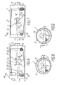
- the lined inner surface of the coarse grinding chamber 85 (FIGS. 3, 4) is provided with projections 19 which are fitted in the long part of the chamber 8b in half the cross section of the housing 1, as is the case here is shown in Fig. 3.
- projections 20 On the lined inner surface of the fine grinding chamber 9b there are projections 20, which are also attached in the long part of the chamber 9b in half the cross section of the housing 1 (FIG. 5).
- the protrusions 19 (Fig. 3) in the chamber 8b are attached to the opposite side of the inner surface of the housing 1 with respect to the protrusions 20 in the chamber 9b.
- the projections 19 in the chamber 8b extend from the cover 2 to the intermediate wall 6.
- the projections 20 in the chamber 9b extend from the cover 3 to the intermediate wall 6.
- the longitudinal axis 22 of the lining surface of a truncated cone 23 is in relation to the longitudinal axis 7 of the housing 1 on the side of the short part of a chamber 24 offset by a dimension "e" (Fig. 6, Fig. 8).
- the longitudinal axis 25 of a truncated cone 26 in a chamber 27 is offset to the side of the short part of the chamber 27 by a dimension "e”.
- the longitudinal axis 25 of the truncated cone 26 is offset with respect to the longitudinal axis 7 of the housing 1 on the opposite side with respect to the longitudinal axis 22 of the truncated cone 23.
- the displacement of the axes 22, 25 is achieved by changing the lining thicknesses in each of the cadres 24, 27.
- the lining of the short part of each of the chambers 24, 27 has a smaller thickness than the lining of the long part of each chamber 24, 27.
- FIGS. 6, 8 show a position of the mill that is rotated by 180 ° with respect to the position of the mill shown in FIGS. 6, 8.
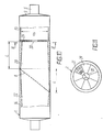
- annular perforated washer 29 (FIG. 10, FIG. 11) is vertically installed in a central grinding chamber 28 (FIG. 10), in the middle part of which a bore 30 is provided. Holes 31 through which the particles of the comminution material pass are made on the entire surface of the annular intermediate disk 29.
- the perforated annular washer 29 is arranged on the side of the short part of the chamber 28 at a distance L from the perforated partition 6, which is not larger than a diameter D of the housing 1.
- the diameter d of the inner bore 30 of the annular perforated intermediate disk 29 is 0.2-0.4 of the diameter D of the mill housing 1.
- Balls are introduced into a coarse grinding chamber 32 and the central grinding chamber 28; cylindrical grinding media (Cylpebs) are introduced into a fine grinding chamber 33.
- the ball mill works as follows.
- the comminuted material is fed into the chamber 8 via the inlet opening 4.
- the perforated partition 6 successively assumes characteristic positions A and B, which are shown in FIGS. 1 and 2, respectively.
- position A of the perforated partition 6 the length of the lower working part of the coarse grinding chamber 8 is minimal, but that of the fine grinding chamber 9 is maximal.
- the perforated partition 6 By moving the perforated partition 6 from position B to position A, it scoops the grinding media located under the perforated partition 6 in section 1 in the coarse grinding chamber 8 and lifts it to an angle from 85 - 90 ° and throws them along the longitudinal axis 7 of the housing towards the cover 2. When falling, the grinding media crush the particles of good quality through intensive blows, through crushing and grinding.
- the length of the lower working part of the fine grinding chamber 9 increases by size 1. whereby the grinding media roll down over the inclined conical lining 11 along the generatrix 13 under the perforated partition 6 and fill the vacated section 1 of the chamber 9. In this case, the good particles are crushed by grinding under the action of the grinding media, which carry out their movement both transversely and along the longitudinal axis 7 of the mill housing 1.
- the perforated partition 6 changes from position A to position B.
- the length of the lower working part of the coarse grinding chamber 8 increases to the maximum size (it increases by 1).
- the grinding media roll along the generatrix 12 of the conical lining 10 below the perforated partition 6 onto the section 1 by crushing the good particles by intensive grinding.
- the perforated partition 6 sucks the grinding media located in section 1 in the chamber 9 with its surface and throws them away along the longitudinal axis 7 towards the cover 3 by crushing the material by impact. Then the cycle is repeated.
- the finished product exits the mill via the discharge opening 5.
- the lined inner surface of the chambers 8, 9, which is designed in the form of the truncated cones 10, 11, which face with their larger bases to the perforated partition 6, creates conditions for a more intensive movement of the grinding media along the longitudinal axis 7 of the mill housing 1 in the Chamber 8 from the cover 2 under the perforated partition 6 and in the chamber 9 from the cover 3 also under the perforated partition 6.
- the grinding media are perforated Partition 6 inevitably moves.
- the grinding media are in such a position in each of the chambers 8, 9 that their surface (not necessarily shown in FIG.) Comes to lie at an angle which is equal to the natural angle of repose of the grinding media in the chamber of ⁇ , ⁇ , that is, the surface of the grinding media is inclined towards the same side as the perforated partition 6. Since the angles of inclination ⁇ , ⁇ of the generators 12, 13 are equal to the natural inclination angles of the grinding media, the (spherical) grinding media lose their equilibrium in the longitudinal direction and automatically roll along the longitudinal axis 7 of the housing 1 to the perforated intermediate wall 6 by moving the working space of chambers 8.9 in section l fill evenly.
- the generators 12, 13 of the truncated cone have different angles of inclination ⁇ , ⁇ .
- each of the chambers 8, 9 is formed by the conical annular sections 14, 16
- the intensity of the longitudinal movement of the grinding media increases from the covers 2, 3 to the perforated intermediate wall 6.
- the grinding efficiency increases when the material is crushed.
- the volume of the coarse grinding chamber H should be smaller than the volume of the fine grinding chamber 9. This is explained by the following.
- an initial product comes through the inlet opening 4, the particles of which have structural defects (microcracks, pores, inclusions that are easy to comminute), and consequently a smaller amount of work is required to comminute them.
- the volume of the chamber should be greater than that of the chamber 8.
- a mill in which the projections 19 (FIG. 3), 20 are attached to the inner surface of its lining works as follows.
- the work of chamber 8b is considered.
- the chamber 8b in the embodiment shown in Fig. 3 position the minimum length 1 1, the grinding media in the chamber take a maximum level one, which ensures a waterfall-like operation of the grinding media.
- the lined surface in the lower short part of the chamber 8b is smooth, ie it has no projections.
- the perforated partition 6 assumes the position 6a.
- the grinding media are scooped from the surface of this partition wall, raised to an angle of 85-90 ° and thrown down along the longitudinal axis 7 of the housing 1, the material being comminuted.
- the grinding media are carried along by the projections 19, raised to an angle of 85-90 ° and thrown off along the longitudinal axis 7 of the housing 1, thereby crushing the material. Then the cycle repeats.
- the grinding media in chamber 9 work similarly, only their movement is 180 out of phase.
- the finished product is led out of the mill housing via the discharge opening 5.
- the working capacity of the chamber 8 becomes higher than the working capacity of the chamber 9, which leads to an excessive amount of the comminution material entering the chamber 9, and the Grinding efficiency drops.
- the lining of the housing 1 (FIG. 6) of the ball mill is carried out as follows.
- the layer thickness of grinding bodies 34 in the chamber 24 is a maximum of h 1 .
- the center of gravity "C" of the grinding bodies 34 lies at a distance R c from the longitudinal axis 7 (axis of rotation) of the housing.
- the grinding media 35 in the chamber 27 have a minimum layer height h 2 , and the distance from the longitudinal axis 7 of the housing 1 to the center of gravity "K" of the grinding media 36 in the chamber 27 is equal to R k .
- the perforated partition 6 assumes a position shown in FIG. 7 after half a revolution.
- the length of the lower working part of the chamber 24 increases up to the maximum value.
- the layer height h 1 'of the grinding media 34 located in the chamber 24 becomes minimal.
- the center of gravity "C" of the grinding media 34 in the chamber 24 shifts to the position R ' c .
- the long part of the chamber 24, which has a greater thickness is located under the grinding media in this position of the housing 1 (FIG. 7).
- the distance R ' c between the center of gravity C 1 of the grinding media located in the chamber 24 and the longitudinal axis 7 in the position shown in FIG. 7 will be the same as the distance R c in the position of the housing shown in FIG. 6 1. Consequently, the torque will be one and the same size, ie it will remain the same during the cycle; the load on the support bearing 21 does not change either.
- the movement of the grinding media in the chamber 27 takes place in a similar manner.
- the length of the lower working part of the chamber 27 becomes minimal.
- the layer height h 2 of the grinding media 35 located in the chamber 27 becomes maximum.
- the center of gravity of the grinding media 35 located in the chamber 27 shifts to the position K 1 .
- the distance R k from the center of gravity K 1 to the longitudinal axis 7 does not change because the part of the lining of the truncated cone 26 with the minimum thickness is located under the grinding bodies 35 in this position of the housing 1.
- the lining of the long and the short part of the chambers 24, 27 will have an equal thickness.
- the distance R and R k also changes from the center of mass of the grinding media to the longitudinal axis 7, and consequently the torque and the load on the support bearings 21 change in size.
- the ball mill When using grinding media which have different shapes, for example balls and cylinders, the ball mill is designed as shown in FIG. 10 and operates as follows.
- the grinding media (the balls), which are located in the chambers 32 and 28 on both sides of the perforated intermediate wall 6, work as well as in the cases dealt with for FIGS. 1 and 2.
- the grinding media in the chamber 33 (Cylpebs) rise under the effect of centrifugal force to an angle of 40-50 °, roll down over the surface of the slope and crush the material by crushing and grinding.
- the finished product is led out of the chamber 33 through the discharge opening 5 in the lid 3.
- the grinding media perform a transverse and longitudinal movement in the chambers 32, 28, while they execute only a transverse movement in the chamber.
- the grinding media pass from the chamber 28 into the chamber 33 and vice versa. As a result, the grinding media in the adjacent chambers 28 and 33 mix and the grinding efficiency drops.
- a reduction in the distance L between the perforated annular washer 29 and the perforated intermediate wall 6 leads to an increase in axial loads which act on the part of the chamber 28 on the perforated annular washer 29, which reduces their operational reliability.
- the Cylpebs (cylinders) have a large natural slope angle and, as a result, a much lower longitudinal mobility.
- the Cylpebs do not move into Zone 1 under the perforated partition, the working space of the chamber is not fully used, the grinding efficiency drops.
- this invention is applicable to the cement industry, ore mining and other industries where it is necessary to finely comminute materials.
Landscapes
- Engineering & Computer Science (AREA)
- Food Science & Technology (AREA)
- Crushing And Grinding (AREA)
- Grinding And Polishing Of Tertiary Curved Surfaces And Surfaces With Complex Shapes (AREA)
Abstract
Un broyeur à boulets comprend une enveloppe (1) montée de manière rotative et dotée d'une surface interne doublée et de fonds (2, 3) également doublés. L'enveloppe est pourvue d'une entrée (4) et d'une sortie (5) et contient au moins une cloison perforée (6) disposée sous un angle (alpha) par rapport à son axe longitudinal et qui divise l'enveloppe en des chambres broyage grossier et fin (8, 9), remplies de corps de broyage. La surface interne doublée des chambres (8, 9) a une forme de cônes tronqués qui sont orientés, par leurs bases plus grandes, vers la cloison perforée (6), l'angle (alpha) d'inclinaison des génératrices (13) étant sensiblement égal à l'angle de glissement naturel des corps de broyage contenus dans la chambre correspondante (8, 9), et le volume de la chambre de broyage grossier (8) étant plus petit qui celui de la chambre de broyage fin (9).
Applications Claiming Priority (1)
| Application Number | Priority Date | Filing Date | Title |
|---|---|---|---|
| PCT/SU1987/000038 WO1988007411A1 (fr) | 1987-03-26 | 1987-03-26 | Broyeur a boulets |
Publications (2)
| Publication Number | Publication Date |
|---|---|
| EP0311686A1 true EP0311686A1 (fr) | 1989-04-19 |
| EP0311686A4 EP0311686A4 (fr) | 1989-10-12 |
Family
ID=21617092
Family Applications (1)
| Application Number | Title | Priority Date | Filing Date |
|---|---|---|---|
| EP19870904364 Withdrawn EP0311686A4 (fr) | 1987-03-26 | 1987-03-26 | Broyeur a boulets. |
Country Status (6)
| Country | Link |
|---|---|
| US (1) | US4867322A (fr) |
| EP (1) | EP0311686A4 (fr) |
| JP (1) | JPH01502726A (fr) |
| DK (1) | DK654688A (fr) |
| IN (1) | IN172021B (fr) |
| WO (1) | WO1988007411A1 (fr) |
Cited By (1)
| Publication number | Priority date | Publication date | Assignee | Title |
|---|---|---|---|---|
| CN115608474A (zh) * | 2022-12-15 | 2023-01-17 | 江苏徐马环保科技有限公司 | 一种废弃物再生用球磨机 |
Families Citing this family (6)
| Publication number | Priority date | Publication date | Assignee | Title |
|---|---|---|---|---|
| RU2209669C1 (ru) * | 2002-01-08 | 2003-08-10 | Кубанский государственный аграрный университет | Барабанная мельница |
| RU2209670C1 (ru) * | 2002-01-08 | 2003-08-10 | Кубанский государственный аграрный университет | Трубная мельница |
| US10493464B2 (en) | 2014-12-18 | 2019-12-03 | Aaron Engineered Process Equipment, Inc. | Rotary mill |
| US10086379B2 (en) | 2015-02-27 | 2018-10-02 | Aaron Engineered Process Equipment, Inc. | Rotary mill |
| RU2685133C1 (ru) * | 2018-02-05 | 2019-04-16 | Федеральное государственное бюджетное образовательное учреждение высшего образования "Кубанский государственный аграрный университет имени И.Т. Трубилина" | Мельница |
| CN109107696B (zh) * | 2018-10-15 | 2020-05-08 | 江西理工大学 | 一种对称组合式螺旋形磨矿筒体及其设计方法 |
Family Cites Families (10)
| Publication number | Priority date | Publication date | Assignee | Title |
|---|---|---|---|---|
| DE308822C (fr) * | ||||
| US1309210A (en) * | 1919-07-08 | Roller-mill | ||
| US1153844A (en) * | 1913-07-21 | 1915-09-14 | Hans A Hansen | Lining for pebble or ball mills. |
| US1683627A (en) * | 1919-12-31 | 1928-09-11 | Alexander M Read | Pulverizing machine |
| GB739578A (en) * | 1954-06-30 | 1955-11-02 | Smidth & Co As F L | Improvements relating to ball or like grinding mills |
| BE736856A (fr) * | 1969-07-31 | 1969-12-31 | ||
| DE2340453A1 (de) * | 1972-10-23 | 1974-05-02 | Oesterr Amerikan Magnesit | Muehle, insbesondere rohr- oder kugelmuehle |
| SU733727A1 (ru) * | 1977-12-02 | 1980-05-15 | Харьковский инженерно-строительный институт | Шарова мельница |
| SU1057108A1 (ru) * | 1982-05-05 | 1983-11-30 | Белгородский технологический институт строительных материалов им.И.А.Гришманова | Футеровка трубной шаровой мельницы |
| SU1090438A1 (ru) * | 1982-10-25 | 1984-05-07 | Белгородский технологический институт строительных материалов им.И.А.Гришманова | Футеровка трубной мельницы |
-
1987
- 1987-03-26 JP JP62503948A patent/JPH01502726A/ja active Pending
- 1987-03-26 EP EP19870904364 patent/EP0311686A4/fr not_active Withdrawn
- 1987-03-26 WO PCT/SU1987/000038 patent/WO1988007411A1/fr not_active Ceased
- 1987-07-10 IN IN582/DEL/87A patent/IN172021B/en unknown
-
1988
- 1988-07-08 US US07/216,519 patent/US4867322A/en not_active Expired - Fee Related
- 1988-11-24 DK DK654688A patent/DK654688A/da not_active Application Discontinuation
Non-Patent Citations (2)
| Title |
|---|
| Keine Entgegenhaltungen. * |
| See also references of WO8807411A1 * |
Cited By (1)
| Publication number | Priority date | Publication date | Assignee | Title |
|---|---|---|---|---|
| CN115608474A (zh) * | 2022-12-15 | 2023-01-17 | 江苏徐马环保科技有限公司 | 一种废弃物再生用球磨机 |
Also Published As
| Publication number | Publication date |
|---|---|
| US4867322A (en) | 1989-09-19 |
| JPH01502726A (ja) | 1989-09-21 |
| DK654688D0 (da) | 1988-11-24 |
| WO1988007411A1 (fr) | 1988-10-06 |
| DK654688A (da) | 1988-11-24 |
| EP0311686A4 (fr) | 1989-10-12 |
| IN172021B (fr) | 1993-03-13 |
Similar Documents
| Publication | Publication Date | Title |
|---|---|---|
| DE4128074C2 (de) | Rührwerkskugelmühle | |
| CH367041A (de) | Siebvorrichtung | |
| DE2148422A1 (de) | Hydrozyklon und Verfahren zum Betreiben eines solchen | |
| DE68911756T2 (de) | Zentrifugalseparator. | |
| EP3311922A1 (fr) | Broyeur à billes à agitateur | |
| DE3938171C1 (fr) | ||
| EP0074076A1 (fr) | Silo, en particulier pour matières en vrac s'écoulant difficilement | |
| DE2200912A1 (de) | Rohrmuehle mit einer oder mehreren Mahlkammern | |
| DE68926105T2 (de) | Vorrichtung und verfahren zum mahlen und pulverisieren | |
| EP0311686A1 (fr) | Broyeur a boulets | |
| AT253337B (de) | Vorrichtung zum fortlaufenden Mahlen und Dispergieren von Feststoffen in Flüssigkeiten | |
| DE1607591A1 (de) | Mahlverfahren und Muehle,um dieses auszufuehren | |
| DE69007435T2 (de) | Vorrichtung zum Zerkleinern und Dispergieren. | |
| DE3731500C2 (fr) | ||
| WO1999004045A1 (fr) | Four vertical | |
| DD268173A1 (de) | Kugelmuehle | |
| DD227339B5 (de) | Ruehrwerksmuehle | |
| EP0288565A1 (fr) | Broyeur tubulaire a bille | |
| DE3624885A1 (de) | Entleerungseinrichtung fuer ein schuettgut-silo | |
| DE4234759C2 (de) | Rührwerkmühle zur Feinstmahlung | |
| DE2124701A1 (de) | Feinmahl werk | |
| EP0245232A2 (fr) | Tube broyeur à billes | |
| CH659008A5 (de) | Traegheitsseparator. | |
| DE2808011C2 (fr) | ||
| DE3741071C2 (de) | Vorrichtung zum Sortieren von Bauschutt in Baustoff und demgegenüber leichtere Bestandteile |
Legal Events
| Date | Code | Title | Description |
|---|---|---|---|
| PUAI | Public reference made under article 153(3) epc to a published international application that has entered the european phase |
Free format text: ORIGINAL CODE: 0009012 |
|
| 17P | Request for examination filed |
Effective date: 19881107 |
|
| AK | Designated contracting states |
Kind code of ref document: A1 Designated state(s): DE FR GB IT SE |
|
| A4 | Supplementary search report drawn up and despatched |
Effective date: 19891012 |
|
| 17Q | First examination report despatched |
Effective date: 19900629 |
|
| STAA | Information on the status of an ep patent application or granted ep patent |
Free format text: STATUS: THE APPLICATION HAS BEEN WITHDRAWN |
|
| 18W | Application withdrawn |
Withdrawal date: 19911107 |
|
| R18W | Application withdrawn (corrected) |
Effective date: 19911107 |