EP0311717A1 - Synchrongeneratoren - Google Patents
Synchrongeneratoren Download PDFInfo
- Publication number
- EP0311717A1 EP0311717A1 EP87308984A EP87308984A EP0311717A1 EP 0311717 A1 EP0311717 A1 EP 0311717A1 EP 87308984 A EP87308984 A EP 87308984A EP 87308984 A EP87308984 A EP 87308984A EP 0311717 A1 EP0311717 A1 EP 0311717A1
- Authority
- EP
- European Patent Office
- Prior art keywords
- stator
- rotor
- generator
- exciter
- electrical
- Prior art date
- Legal status (The legal status is an assumption and is not a legal conclusion. Google has not performed a legal analysis and makes no representation as to the accuracy of the status listed.)
- Withdrawn
Links
- 230000001360 synchronised effect Effects 0.000 title claims description 20
- 230000006872 improvement Effects 0.000 title claims description 6
- 239000003990 capacitor Substances 0.000 claims abstract description 6
- 238000004804 winding Methods 0.000 claims description 25
- 230000001939 inductive effect Effects 0.000 claims description 17
- 230000004907 flux Effects 0.000 claims description 12
- 230000004044 response Effects 0.000 claims description 7
- 238000012937 correction Methods 0.000 claims description 3
- 230000008878 coupling Effects 0.000 claims description 3
- 238000010168 coupling process Methods 0.000 claims description 3
- 238000005859 coupling reaction Methods 0.000 claims description 3
- 230000005284 excitation Effects 0.000 claims 3
- 150000001875 compounds Chemical class 0.000 abstract description 3
- 230000000694 effects Effects 0.000 description 19
- 239000013598 vector Substances 0.000 description 19
- 230000006698 induction Effects 0.000 description 13
- ATJFFYVFTNAWJD-UHFFFAOYSA-N Tin Chemical compound [Sn] ATJFFYVFTNAWJD-UHFFFAOYSA-N 0.000 description 7
- 230000008901 benefit Effects 0.000 description 4
- 238000003780 insertion Methods 0.000 description 4
- 230000037431 insertion Effects 0.000 description 4
- 239000004020 conductor Substances 0.000 description 3
- 230000003190 augmentative effect Effects 0.000 description 2
- 230000008859 change Effects 0.000 description 2
- 238000010276 construction Methods 0.000 description 2
- 238000010586 diagram Methods 0.000 description 2
- 238000006073 displacement reaction Methods 0.000 description 2
- 230000006870 function Effects 0.000 description 2
- 238000000034 method Methods 0.000 description 2
- 238000012986 modification Methods 0.000 description 2
- 230000004048 modification Effects 0.000 description 2
- 230000008447 perception Effects 0.000 description 2
- 230000002441 reversible effect Effects 0.000 description 2
- 230000003068 static effect Effects 0.000 description 2
- 230000008093 supporting effect Effects 0.000 description 2
- 238000012935 Averaging Methods 0.000 description 1
- RYGMFSIKBFXOCR-UHFFFAOYSA-N Copper Chemical compound [Cu] RYGMFSIKBFXOCR-UHFFFAOYSA-N 0.000 description 1
- 230000004075 alteration Effects 0.000 description 1
- 238000013459 approach Methods 0.000 description 1
- 230000002238 attenuated effect Effects 0.000 description 1
- 230000003416 augmentation Effects 0.000 description 1
- 230000009286 beneficial effect Effects 0.000 description 1
- 230000000295 complement effect Effects 0.000 description 1
- 229910052802 copper Inorganic materials 0.000 description 1
- 239000010949 copper Substances 0.000 description 1
- 238000006880 cross-coupling reaction Methods 0.000 description 1
- 230000005288 electromagnetic effect Effects 0.000 description 1
- 230000001976 improved effect Effects 0.000 description 1
- 238000002955 isolation Methods 0.000 description 1
- 239000000463 material Substances 0.000 description 1
- 230000007246 mechanism Effects 0.000 description 1
- 230000036961 partial effect Effects 0.000 description 1
- 230000009467 reduction Effects 0.000 description 1
- 230000002829 reductive effect Effects 0.000 description 1
- 230000001105 regulatory effect Effects 0.000 description 1
- 238000006467 substitution reaction Methods 0.000 description 1
- 238000012360 testing method Methods 0.000 description 1
- XLYOFNOQVPJJNP-UHFFFAOYSA-N water Substances O XLYOFNOQVPJJNP-UHFFFAOYSA-N 0.000 description 1
Images

Classifications
-
- H—ELECTRICITY
- H02—GENERATION; CONVERSION OR DISTRIBUTION OF ELECTRIC POWER
- H02P—CONTROL OR REGULATION OF ELECTRIC MOTORS, ELECTRIC GENERATORS OR DYNAMO-ELECTRIC CONVERTERS; CONTROLLING TRANSFORMERS, REACTORS OR CHOKE COILS
- H02P9/00—Arrangements for controlling electric generators for the purpose of obtaining a desired output
- H02P9/42—Arrangements for controlling electric generators for the purpose of obtaining a desired output to obtain desired frequency without varying speed of the generator
-
- H—ELECTRICITY
- H02—GENERATION; CONVERSION OR DISTRIBUTION OF ELECTRIC POWER
- H02K—DYNAMO-ELECTRIC MACHINES
- H02K19/00—Synchronous motors or generators
- H02K19/16—Synchronous generators
- H02K19/26—Synchronous generators characterised by the arrangement of exciting windings
-
- H—ELECTRICITY
- H02—GENERATION; CONVERSION OR DISTRIBUTION OF ELECTRIC POWER
- H02K—DYNAMO-ELECTRIC MACHINES
- H02K99/00—Subject matter not provided for in other groups of this subclass
- H02K99/10—Generators
-
- H—ELECTRICITY
- H02—GENERATION; CONVERSION OR DISTRIBUTION OF ELECTRIC POWER
- H02P—CONTROL OR REGULATION OF ELECTRIC MOTORS, ELECTRIC GENERATORS OR DYNAMO-ELECTRIC CONVERTERS; CONTROLLING TRANSFORMERS, REACTORS OR CHOKE COILS
- H02P9/00—Arrangements for controlling electric generators for the purpose of obtaining a desired output
- H02P9/007—Control circuits for doubly fed generators
Definitions
- the present invention relates to electrical generators, and more particularly to improvements in synchronous generators referenced to an AC signal.
- Yet further objects of the invention are to provide a portable electrical generator which is self regulated to a selected frequency and optimized generation.
- a singly fed device i.e., an induction device
- the rotor current also includes externally induced currents, i.e., the current induced in the other stage a compound result obtains with the beneficial aspects of both a synchronous and a singly fed configuration.
- the relative exciter and generator slip rates are opposite. In the cross-connected rotor stages these torques can be balanced out by the insertion of the balancing resistance and reactance into the rotor loop. This then distributes the torques between the exciter and generator stages, and each individual stage will therefore not limit the dynamic range of the device.
- the reactive (capacitive) connection across this resistor will serve to reduce its effects as the input shaft rate increases.
- the inventive device can be set to select an exciter - generator torque distribution by the expediently inserted resistance which is then augmented by capacitance.
- the inverted (push-pull) rotor connection substantially reduces the effect that is normally associated with a singly fed device. Moreover intentional insertion of resistance into the rotor loop provides a potential (drop) across which the torques are effectively balanced. This insertion of resistance (and reactance) greatly expands the operating (dynamic) range of the generator assembly without the necessity of continual phase adjustments of the stators.
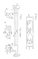
- a prior art synchronous generator of the type previously described by me in my U.S. Patent No. 4,229,689 is generally illustrated herein at 10 and for purposes of completeness of the instant disclosure is shown to include an exciter stator 11 mounted on rollers 12 for angular motion in response to the rotary advancement of a worm gear 13 engaging a rack segment 14.
- This exciter stator is generally of an annular construction provided with a plurality of magnetic pole pieces each having wound thereabout a corresponding electrical lead shown as electrical leads 16, 17 and 18.
- Received within the annular interior of the exciter stator is one segment of a rotor, generally shown at 20, including an exciter rotor section 21 aligned for rotation inside the magnetic pole pieces of the stator 11.
- Rotor 21, similar to stator 11, includes its own set of magnetic pole pieces each again wound by an electric lead shown as electrical leads 26, 27 and 28. These same electrical leads pass to the other segment of the rotor 20, shown herein as the generator rotor stage 22, as previously described, being connected in opposite polarity to the exciter rotor 21. Thus, the electrical leads 26, 27 and 28 form oppositely aligned and directed magnetic vectors in rotor stages 21 and 22 as a consequence to any induced current passed therein.
- Rotor stage 22, moreover, is received within the interior of a generator stator 31, once again provided with the same number of poles as the exciter stator 11 and including electrical leads around around each pole shown as electrical leads 36, 37 and 38. Leads 16, 17 and 18 and 36, 37 and 38 are respectively connected to a three-phase line P6, P7 and P8 which are then plugged into a utility grid shown generally at U.
- the exciter stator 11 will exhibit a sinusoidally shaped flux field SSF rotating at the rate MS and aligned along the vector VS. Flux field SSF will then induce in the exciter rotor a rotor current field (sheet) RCF lagging behind vector VA at a lagging vector VB which then results in an orthogonal rotor magnetomotive wave RMF along a vector VC.
- the exciter rotor 21 is fixed to a common shaft 51 driven in rotation at the shaft rate N by a prime mover PM. As previously set out the resulting rate of vector VC relative the shaft 51 is the sum of the rate MS and the shaft rate N.
- the mmf wave GMF in the generator rotor aligns along a vector GC at an alignment substantially out of phase with vector VC.
- the local current curve GCF then aligns at a vector GB to induce (generate) a power output GSF at a vector GA.
- the rate and phase of vector GA is consistent with the rate MS of vector VA.
- the consequent induced current wave forms in rotors 21 and 22 are generally opposite and accordingly effect the push-pull induction previously described. Nonetheless, because of the cross-connection the rate of vector GC relative its field vector GA will be higher than the rate of vector VC relative VA.
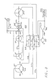
- two distinct relative frequencies are impressed, which can then be controlled (attenuated) by a series connection of an R-C network (220 and C20).
- the inverted circuit equivalent provides an effective current gain in the secondary loop.
- This gain expresses the current ratio of an inverted against an uninverted configuration of the secondary loop.
- the singular respect of this circuit is in the out-of-phase components of the secondary loop, i.e., its power factor.
- a resistor R20 By inserting a resistor R20 into the current loop I20 which is two or more times greater than the out-of-phase equivalent real or in phase power is realized in the secondary and since the current gain is high little loss occurs as a consequence.
- a capacitor C20 may also be inserted which then also selects the higher frequency. In this manner the power factor problems associated with the imposed slip rates RE are effectively taken out without a significant reduction in efficiency.
- the device thus implemented will then accommodate a wide range of shaft rates N in total distinction to the limited dynamic range of conventional inductive devices, and at the same time shall produce a fully synchronized power output.
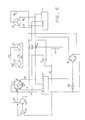
- phase comparator 151 compares the signals on leads 16 and 36 to produce a difference signal E to a servo amplifier 152 driving a servo motor 153 connected (through gearing or otherwise) to the worm gear 13.
- the angular position of worm gear 13 and thus the angular position of the stator 11 is then picked off through the position of a potentiometer 154 to provide a position feed-back signal to amplifier 152 to complete the loop.
- an angular error signal E is provided in response to the phase difference between the signals on leads 16 and 36 and will be nulled out by the appropriate correction in the stator alignment.
- this error signal E passes through a solenoid coil 65 to pull open a spring-loaded gang switch 56 forming the connection between leads 16 and 36, 17 and 37 and 18 and 38.
- Leads 16, 17 and 18, moreover, may connect to an inverter 75 and thus carry thereon the inverter output of a selected frequency and phase. Accordingly, the phase angle adjustment will continue until full phase alignment is made between inverter 75, stator 11 and stator 31 which is tied to the lead L, thus fixing the output of the generator to the angles of the load.
- Inverter 75 is, furthermore, connected to a battery 80 which may be recharged by a full wave rectifier 81 connected across two of the output leads from the generator stage 31.
- a load L across leads 36, 37 and 38 will then receive power fixed to the frequency rate and phase angle of inverter 75 and on each occurrence of a substantial phase change due to the change in load L a servo correction will follow to correct the phase differences in the circuit.
- a self-correcting, battery powered, inverter referenced generator is provided which is available for use with any prime mover such as a windmill or a waterwheel and can be therefore conveniently set up in remote areas.
- any inverter of commercial quality may be useful herein and the necessity of the description of the features thereof is therefore not required, and the rotor assembly 20 includes the foregoing series impedances to accommodate prime mover variations.
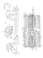
- each of the stators 11 and 31 includes a corresponding corepiece 111 and 131 which, in conventional manner, carries the field windings 211 and 231.
- Core piece 111 is mounted on rollers 12 for advancement by the screw 13 within the interior of a common cylindrical housing 200.
- Housing 200 includes end plates 201 and 202 each supporting a bearing 203 and 204 supporting shaft 51 keyed by keys 221 and 222 to core pieces 121 and 122 forming rotors 21 and 22.
- both core pieces 111 and 131 include shielding rings 311 and 331 which align to collect the fringe flux patterns of the rotor core pieces rotating therein.
- isolation shaft 51 may be made of nonmagnetic material and may be center supported by bearings 303 and 304 in a center web 300.
- an alternative implementation shown generally at 500 comprises a shaft 551 including slip rings 552, 553 and 554 mounted at one end thereof.
- Each slip ring maintains sliding contact with a corresponding wiper 552a, 553a and 554a connected to leads U1, U2 and U3 of a three-phase public utility grid U.
- Rings 552, 553 and 554 then connect in parallel to the windings of a first stator assembly 511 and a second stator assembly 531 which in this case are mounted for common rotation on shaft 551. Accordingly, in this instance the operation of the rotors and the stators is reversed from that previously set out and the stators are therefore in rotation.
- Stators 511 and 531 are aligned for rotation within the interior of stationary rotors 521 and 522 of annular 3-phase configuration like the stators 11 and 31.
- the stationary rotors are, again, interconnected in an inverted connection by leads 526, 527 and 528 each provided with a corresponding potentiometer 626, 627 and 628.
- capacitors 726, 727 and 728 are, again, in parallel with capacitors 726, 727 and 728.
- the potentiometers now stationary, are available for either manual or automated control exemplified herein by a servo loop 580 comprising a motor 581 connected in common by a shaft 582 to the wipers of each potentiometer.
- the servo motor 581 is driven by an amplifier 583 which responds to the voltage difference across one of the potentiometers, e.g., potentiometer 626 and a control signal input from a reference source 585. Accordingly, control is obtained over the relative amplitude of the curve DF in Figure 5 and thus the power of output of the device.
- the stationary rotor 521 may, furthermore, be controlled in phase by rotation achieved through rollers 512 and a screw arrangement 513.
Landscapes
- Engineering & Computer Science (AREA)
- Power Engineering (AREA)
- Control Of Eletrric Generators (AREA)
Applications Claiming Priority (1)
| Application Number | Priority Date | Filing Date | Title |
|---|---|---|---|
| US06/876,481 US4701691A (en) | 1985-05-14 | 1986-06-20 | Synchronous generators |
Publications (1)
| Publication Number | Publication Date |
|---|---|
| EP0311717A1 true EP0311717A1 (de) | 1989-04-19 |
Family
ID=25367814
Family Applications (1)
| Application Number | Title | Priority Date | Filing Date |
|---|---|---|---|
| EP87308984A Withdrawn EP0311717A1 (de) | 1986-06-20 | 1987-10-12 | Synchrongeneratoren |
Country Status (2)
| Country | Link |
|---|---|
| US (1) | US4701691A (de) |
| EP (1) | EP0311717A1 (de) |
Cited By (3)
| Publication number | Priority date | Publication date | Assignee | Title |
|---|---|---|---|---|
| US5406190A (en) * | 1991-11-07 | 1995-04-11 | Siemens Aktiengesellschaft | Device for generating electrical energy having an A.C. generator coupled to a turbine |
| WO1998059410A1 (de) * | 1997-06-24 | 1998-12-30 | Frank Eckert | Elektrodynamische maschine, nämlich synchrongenerator und/oder -motor |
| CN105340171A (zh) * | 2013-05-08 | 2016-02-17 | 伦策驱动有限公司 | 驱动系统 |
Families Citing this family (23)
| Publication number | Priority date | Publication date | Assignee | Title |
|---|---|---|---|---|
| US4982147A (en) * | 1989-01-30 | 1991-01-01 | State Of Oregon Acting By And Through The State Board Of Higher Education On Behalf Of Oregon State University | Power factor motor control system |
| US4994684A (en) * | 1989-01-30 | 1991-02-19 | The State Of Oregon Acting By And Through The State Board Of Higher Education On Behalf Of Oregon State University | Doubly fed generator variable speed generation control system |
| US5239251A (en) * | 1989-06-30 | 1993-08-24 | The State Of Oregon Acting By And Through The State Board Of Higher Education On Behalf Of Oregon State University | Brushless doubly-fed motor control system |
| US5028804A (en) * | 1989-06-30 | 1991-07-02 | The State Of Oregon Acting By And Through The State Board Of Higher Education On Behalf Of Oregon State University | Brushless doubly-fed generator control system |
| US5083077A (en) * | 1990-07-31 | 1992-01-21 | The State Of Oregon Acting By And Through The State Board Of Higher Education On Behalf Of Oregon State University | Brushless doubly-fed generation system for vehicles |
| US5418446A (en) * | 1993-05-10 | 1995-05-23 | Hallidy; William M. | Variable speed constant frequency synchronous electric power generating system and method of using same |
| SE9602079D0 (sv) * | 1996-05-29 | 1996-05-29 | Asea Brown Boveri | Roterande elektriska maskiner med magnetkrets för hög spänning och ett förfarande för tillverkning av densamma |
| AU3185397A (en) * | 1996-06-25 | 1998-01-14 | John Judson | A.c. electrical machine and method of transducing power between two different systems |
| US20040041480A1 (en) * | 1997-02-07 | 2004-03-04 | Nickoladze Leo G. | Method and apparatus for compensating a line synchronous generator |
| AU6323698A (en) * | 1997-02-07 | 1998-09-09 | Estate of Leo G. Nickoladze, Deceased, The | Method and apparatus for compensating a line synchronous generator |
| KR100980063B1 (ko) * | 1997-02-07 | 2010-09-03 | 디 이스테이트 오브 레오 지. 니콜라즈, 디시스트 | 3상 라인 동기 발전기의 위상 정렬을 결정하는 방법 |
| US20020180296A1 (en) * | 1998-02-27 | 2002-12-05 | Foundation Gni, Ltd. | Variable speed constant frequency motor |
| US6310417B1 (en) * | 1999-12-30 | 2001-10-30 | Lockheed Martin Energy Research Corporation | Hybrid-secondary uncluttered induction machine |
| US6639866B2 (en) * | 2000-11-03 | 2003-10-28 | Broadcom Corporation | Very small swing high performance asynchronous CMOS static memory (multi-port register file) with power reducing column multiplexing scheme |
| US6784634B2 (en) * | 2001-09-14 | 2004-08-31 | Edwin A. Sweo | Brushless doubly-fed induction machine control |
| US6909263B2 (en) * | 2002-10-23 | 2005-06-21 | Honeywell International Inc. | Gas turbine engine starter-generator exciter starting system and method including a capacitance circuit element |
| US7161257B2 (en) * | 2004-03-08 | 2007-01-09 | Ingersoll-Rand Energy Systems, Inc. | Active anti-islanding system and method |
| FR2881896B1 (fr) * | 2005-02-04 | 2011-06-10 | Airbus France | Systeme de generation electrique a frequence fixe a coupleur a induction et utilisation de celui-ci dans un aeronef |
| US7425771B2 (en) * | 2006-03-17 | 2008-09-16 | Ingeteam S.A. | Variable speed wind turbine having an exciter machine and a power converter not connected to the grid |
| CN101401294B (zh) * | 2006-03-17 | 2013-04-17 | 英捷电力技术有限公司 | 具有激励器设备和不连接至电网的功率变换器的变速风机 |
| JP4693865B2 (ja) * | 2007-08-27 | 2011-06-01 | 株式会社豊田中央研究所 | 動力伝達装置 |
| US8198743B2 (en) * | 2009-09-11 | 2012-06-12 | Honeywell International, Inc. | Multi-stage controlled frequency generator for direct-drive wind power |
| US10014748B2 (en) * | 2013-10-22 | 2018-07-03 | Edward LIVINGSTON | Coaxial direct drive system having at least two primer movers linearly moveable along a drive support member |
Citations (6)
| Publication number | Priority date | Publication date | Assignee | Title |
|---|---|---|---|---|
| US3183431A (en) * | 1961-01-23 | 1965-05-11 | Sundstrand Corp | Constant frequency brushless generating system |
| AT264670B (de) * | 1966-03-22 | 1968-09-10 | Elin Union Ag | Maschineneinsatz bestehend aus Synchrongenerator, Wechsel- bzw. Drehstromerregermaschine und Hilfserregermaschine |
| AT270817B (de) * | 1966-10-18 | 1969-05-12 | Bbc Brown Boveri & Cie | Erregeranordnung eines schleifringlosen, mit rotierenden Dioden versehenen Synchronmotors |
| EP0028468A1 (de) * | 1979-11-05 | 1981-05-13 | Khartli, Inc | Wechselstromgenerator |
| US4305001A (en) * | 1979-02-26 | 1981-12-08 | Lima Electric Company, Inc. | Constant frequency alternator |
| US4409491A (en) * | 1982-12-27 | 1983-10-11 | Schott Lawrence A | AC Frequency and phase synchronizer |
Family Cites Families (2)
| Publication number | Priority date | Publication date | Assignee | Title |
|---|---|---|---|---|
| US3200324A (en) * | 1960-02-29 | 1965-08-10 | Dudley W Wagner | Rotating electrical machine with multiple rotors in paired relation |
| US3122696A (en) * | 1961-01-09 | 1964-02-25 | Siegler Corp | Control apparatus for alternating current dynamoelectric machines |
-
1986
- 1986-06-20 US US06/876,481 patent/US4701691A/en not_active Expired - Lifetime
-
1987
- 1987-10-12 EP EP87308984A patent/EP0311717A1/de not_active Withdrawn
Patent Citations (6)
| Publication number | Priority date | Publication date | Assignee | Title |
|---|---|---|---|---|
| US3183431A (en) * | 1961-01-23 | 1965-05-11 | Sundstrand Corp | Constant frequency brushless generating system |
| AT264670B (de) * | 1966-03-22 | 1968-09-10 | Elin Union Ag | Maschineneinsatz bestehend aus Synchrongenerator, Wechsel- bzw. Drehstromerregermaschine und Hilfserregermaschine |
| AT270817B (de) * | 1966-10-18 | 1969-05-12 | Bbc Brown Boveri & Cie | Erregeranordnung eines schleifringlosen, mit rotierenden Dioden versehenen Synchronmotors |
| US4305001A (en) * | 1979-02-26 | 1981-12-08 | Lima Electric Company, Inc. | Constant frequency alternator |
| EP0028468A1 (de) * | 1979-11-05 | 1981-05-13 | Khartli, Inc | Wechselstromgenerator |
| US4409491A (en) * | 1982-12-27 | 1983-10-11 | Schott Lawrence A | AC Frequency and phase synchronizer |
Non-Patent Citations (1)
| Title |
|---|
| PATENT ABSTRACTS OF JAPAN, vol. 7, no. 40 (E-159)[1185], 17th February 1983; & JP - A - 57 193 995 (FUKUO SHIBATA) 29-11-1982 * |
Cited By (4)
| Publication number | Priority date | Publication date | Assignee | Title |
|---|---|---|---|---|
| US5406190A (en) * | 1991-11-07 | 1995-04-11 | Siemens Aktiengesellschaft | Device for generating electrical energy having an A.C. generator coupled to a turbine |
| WO1998059410A1 (de) * | 1997-06-24 | 1998-12-30 | Frank Eckert | Elektrodynamische maschine, nämlich synchrongenerator und/oder -motor |
| CN105340171A (zh) * | 2013-05-08 | 2016-02-17 | 伦策驱动有限公司 | 驱动系统 |
| US10263557B2 (en) | 2013-05-08 | 2019-04-16 | Lenze Drives Gmbh | Drive system |
Also Published As
| Publication number | Publication date |
|---|---|
| US4701691A (en) | 1987-10-20 |
Similar Documents
| Publication | Publication Date | Title |
|---|---|---|
| US4701691A (en) | Synchronous generators | |
| CA1148216A (en) | Ac synchronized generator | |
| EP1018211B1 (de) | Verfahren und vorrichtung zur kompensation eines synchrongenerators mit sektoren | |
| EP0700596B1 (de) | Synchrones elektrisches stromversorgungssystem mit variabler geschwindigkeit und konstanter frequenz und verfahren zu seiner verwendung | |
| US20080303367A1 (en) | Variable speed constant frequency motor | |
| US20130181561A1 (en) | Method and apparatus for compensating a line synchronous generator | |
| US5274291A (en) | Rotary transformer with multiple angularly adjustable stators | |
| US3483463A (en) | System and method for alternating current machines,and apparatus therefor | |
| GB2055515A (en) | Frequency Converting Arrangement | |
| US2444077A (en) | Polyphase induction machine and control | |
| US3210644A (en) | Dynamo electric machine | |
| CA1279888C (en) | Synchronous generators | |
| CN110492643B (zh) | 适合海水抽水蓄能电站的发电电动机 | |
| US4585984A (en) | Alternating current motor | |
| Smith | Synchronous-flux generator | |
| US2725490A (en) | Electric power system | |
| JPH01122399A (ja) | 同期電動機 | |
| GB2056183A (en) | Alternating current generating equipment | |
| US1423959A (en) | Frequency changer | |
| AU7876587A (en) | Single and polyphase electromagnetic induction machines having regulated polar magnetic symmetry | |
| US2515496A (en) | Electrical machine for selfsynchronous systems | |
| KR830002509B1 (ko) | 교류 발전기 | |
| US2456442A (en) | Electromechanical oscillator | |
| SU320004A1 (ru) | Способ управления машиной двойного питания | |
| Clayton | Power Factor Correction: Explaining the Meaning and Importance of Power Factor, and Describing Methods for the Improvement of Power Factor |
Legal Events
| Date | Code | Title | Description |
|---|---|---|---|
| PUAI | Public reference made under article 153(3) epc to a published international application that has entered the european phase |
Free format text: ORIGINAL CODE: 0009012 |
|
| AK | Designated contracting states |
Kind code of ref document: A1 Designated state(s): AT BE CH DE ES FR GB GR IT LI LU NL SE |
|
| 17P | Request for examination filed |
Effective date: 19891019 |
|
| 17Q | First examination report despatched |
Effective date: 19910516 |
|
| STAA | Information on the status of an ep patent application or granted ep patent |
Free format text: STATUS: THE APPLICATION IS DEEMED TO BE WITHDRAWN |
|
| 18D | Application deemed to be withdrawn |
Effective date: 19910927 |