EP0312033A2 - Recirculation de gaz d'echappement pour moteur diesel - Google Patents
Recirculation de gaz d'echappement pour moteur diesel Download PDFInfo
- Publication number
- EP0312033A2 EP0312033A2 EP88116966A EP88116966A EP0312033A2 EP 0312033 A2 EP0312033 A2 EP 0312033A2 EP 88116966 A EP88116966 A EP 88116966A EP 88116966 A EP88116966 A EP 88116966A EP 0312033 A2 EP0312033 A2 EP 0312033A2
- Authority
- EP
- European Patent Office
- Prior art keywords
- exhaust gas
- gas recirculation
- temperature
- engine
- pipe
- Prior art date
- Legal status (The legal status is an assumption and is not a legal conclusion. Google has not performed a legal analysis and makes no representation as to the accuracy of the status listed.)
- Withdrawn
Links
Images
Classifications
-
- F—MECHANICAL ENGINEERING; LIGHTING; HEATING; WEAPONS; BLASTING
- F02—COMBUSTION ENGINES; HOT-GAS OR COMBUSTION-PRODUCT ENGINE PLANTS
- F02D—CONTROLLING COMBUSTION ENGINES
- F02D9/00—Controlling engines by throttling air or fuel-and-air induction conduits or exhaust conduits
- F02D9/02—Controlling engines by throttling air or fuel-and-air induction conduits or exhaust conduits concerning induction conduits
-
- F—MECHANICAL ENGINEERING; LIGHTING; HEATING; WEAPONS; BLASTING
- F02—COMBUSTION ENGINES; HOT-GAS OR COMBUSTION-PRODUCT ENGINE PLANTS
- F02M—SUPPLYING COMBUSTION ENGINES IN GENERAL WITH COMBUSTIBLE MIXTURES OR CONSTITUENTS THEREOF
- F02M26/00—Engine-pertinent apparatus for adding exhaust gases to combustion-air, main fuel or fuel-air mixture, e.g. by exhaust gas recirculation [EGR] systems
- F02M26/13—Arrangement or layout of EGR passages, e.g. in relation to specific engine parts or for incorporation of accessories
- F02M26/14—Arrangement or layout of EGR passages, e.g. in relation to specific engine parts or for incorporation of accessories in relation to the exhaust system
- F02M26/15—Arrangement or layout of EGR passages, e.g. in relation to specific engine parts or for incorporation of accessories in relation to the exhaust system in relation to engine exhaust purifying apparatus
-
- F—MECHANICAL ENGINEERING; LIGHTING; HEATING; WEAPONS; BLASTING
- F02—COMBUSTION ENGINES; HOT-GAS OR COMBUSTION-PRODUCT ENGINE PLANTS
- F02M—SUPPLYING COMBUSTION ENGINES IN GENERAL WITH COMBUSTIBLE MIXTURES OR CONSTITUENTS THEREOF
- F02M26/00—Engine-pertinent apparatus for adding exhaust gases to combustion-air, main fuel or fuel-air mixture, e.g. by exhaust gas recirculation [EGR] systems
- F02M26/13—Arrangement or layout of EGR passages, e.g. in relation to specific engine parts or for incorporation of accessories
- F02M26/40—Arrangement or layout of EGR passages, e.g. in relation to specific engine parts or for incorporation of accessories with timing means in the recirculation passage, e.g. cyclically operating valves or regenerators; with arrangements involving pressure pulsations
-
- F—MECHANICAL ENGINEERING; LIGHTING; HEATING; WEAPONS; BLASTING
- F02—COMBUSTION ENGINES; HOT-GAS OR COMBUSTION-PRODUCT ENGINE PLANTS
- F02M—SUPPLYING COMBUSTION ENGINES IN GENERAL WITH COMBUSTIBLE MIXTURES OR CONSTITUENTS THEREOF
- F02M26/00—Engine-pertinent apparatus for adding exhaust gases to combustion-air, main fuel or fuel-air mixture, e.g. by exhaust gas recirculation [EGR] systems
- F02M26/45—Sensors specially adapted for EGR systems
- F02M26/46—Sensors specially adapted for EGR systems for determining the characteristics of gases, e.g. composition
- F02M26/47—Sensors specially adapted for EGR systems for determining the characteristics of gases, e.g. composition the characteristics being temperatures, pressures or flow rates
-
- F—MECHANICAL ENGINEERING; LIGHTING; HEATING; WEAPONS; BLASTING
- F02—COMBUSTION ENGINES; HOT-GAS OR COMBUSTION-PRODUCT ENGINE PLANTS
- F02M—SUPPLYING COMBUSTION ENGINES IN GENERAL WITH COMBUSTIBLE MIXTURES OR CONSTITUENTS THEREOF
- F02M26/00—Engine-pertinent apparatus for adding exhaust gases to combustion-air, main fuel or fuel-air mixture, e.g. by exhaust gas recirculation [EGR] systems
- F02M26/52—Systems for actuating EGR valves
- F02M26/59—Systems for actuating EGR valves using positive pressure actuators; Check valves therefor
- F02M26/60—Systems for actuating EGR valves using positive pressure actuators; Check valves therefor in response to air intake pressure
-
- F—MECHANICAL ENGINEERING; LIGHTING; HEATING; WEAPONS; BLASTING
- F02—COMBUSTION ENGINES; HOT-GAS OR COMBUSTION-PRODUCT ENGINE PLANTS
- F02M—SUPPLYING COMBUSTION ENGINES IN GENERAL WITH COMBUSTIBLE MIXTURES OR CONSTITUENTS THEREOF
- F02M26/00—Engine-pertinent apparatus for adding exhaust gases to combustion-air, main fuel or fuel-air mixture, e.g. by exhaust gas recirculation [EGR] systems
- F02M26/52—Systems for actuating EGR valves
- F02M26/63—Systems for actuating EGR valves the EGR valve being directly controlled by an operator
-
- F—MECHANICAL ENGINEERING; LIGHTING; HEATING; WEAPONS; BLASTING
- F02—COMBUSTION ENGINES; HOT-GAS OR COMBUSTION-PRODUCT ENGINE PLANTS
- F02M—SUPPLYING COMBUSTION ENGINES IN GENERAL WITH COMBUSTIBLE MIXTURES OR CONSTITUENTS THEREOF
- F02M31/00—Apparatus for thermally treating combustion-air, fuel, or fuel-air mixture
- F02M31/02—Apparatus for thermally treating combustion-air, fuel, or fuel-air mixture for heating
- F02M31/04—Apparatus for thermally treating combustion-air, fuel, or fuel-air mixture for heating combustion-air or fuel-air mixture
- F02M31/06—Apparatus for thermally treating combustion-air, fuel, or fuel-air mixture for heating combustion-air or fuel-air mixture by hot gases, e.g. by mixing cold and hot air
- F02M31/07—Temperature-responsive control, e.g. using thermostatically-controlled valves
-
- F—MECHANICAL ENGINEERING; LIGHTING; HEATING; WEAPONS; BLASTING
- F02—COMBUSTION ENGINES; HOT-GAS OR COMBUSTION-PRODUCT ENGINE PLANTS
- F02B—INTERNAL-COMBUSTION PISTON ENGINES; COMBUSTION ENGINES IN GENERAL
- F02B75/00—Other engines
- F02B75/16—Engines characterised by number of cylinders, e.g. single-cylinder engines
- F02B75/18—Multi-cylinder engines
- F02B2075/1804—Number of cylinders
- F02B2075/182—Number of cylinders five
-
- F—MECHANICAL ENGINEERING; LIGHTING; HEATING; WEAPONS; BLASTING
- F02—COMBUSTION ENGINES; HOT-GAS OR COMBUSTION-PRODUCT ENGINE PLANTS
- F02B—INTERNAL-COMBUSTION PISTON ENGINES; COMBUSTION ENGINES IN GENERAL
- F02B3/00—Engines characterised by air compression and subsequent fuel addition
- F02B3/06—Engines characterised by air compression and subsequent fuel addition with compression ignition
-
- F—MECHANICAL ENGINEERING; LIGHTING; HEATING; WEAPONS; BLASTING
- F02—COMBUSTION ENGINES; HOT-GAS OR COMBUSTION-PRODUCT ENGINE PLANTS
- F02D—CONTROLLING COMBUSTION ENGINES
- F02D9/00—Controlling engines by throttling air or fuel-and-air induction conduits or exhaust conduits
- F02D9/02—Controlling engines by throttling air or fuel-and-air induction conduits or exhaust conduits concerning induction conduits
- F02D2009/0201—Arrangements; Control features; Details thereof
- F02D2009/0222—Exhaust gas temperature
-
- F—MECHANICAL ENGINEERING; LIGHTING; HEATING; WEAPONS; BLASTING
- F02—COMBUSTION ENGINES; HOT-GAS OR COMBUSTION-PRODUCT ENGINE PLANTS
- F02D—CONTROLLING COMBUSTION ENGINES
- F02D9/00—Controlling engines by throttling air or fuel-and-air induction conduits or exhaust conduits
- F02D9/02—Controlling engines by throttling air or fuel-and-air induction conduits or exhaust conduits concerning induction conduits
- F02D2009/0201—Arrangements; Control features; Details thereof
- F02D2009/0276—Throttle and EGR-valve operated together
-
- F—MECHANICAL ENGINEERING; LIGHTING; HEATING; WEAPONS; BLASTING
- F02—COMBUSTION ENGINES; HOT-GAS OR COMBUSTION-PRODUCT ENGINE PLANTS
- F02M—SUPPLYING COMBUSTION ENGINES IN GENERAL WITH COMBUSTIBLE MIXTURES OR CONSTITUENTS THEREOF
- F02M26/00—Engine-pertinent apparatus for adding exhaust gases to combustion-air, main fuel or fuel-air mixture, e.g. by exhaust gas recirculation [EGR] systems
- F02M2026/001—Arrangements; Control features; Details
- F02M2026/004—EGR valve controlled by a temperature signal or an air/fuel ratio (lambda) signal
-
- F—MECHANICAL ENGINEERING; LIGHTING; HEATING; WEAPONS; BLASTING
- F02—COMBUSTION ENGINES; HOT-GAS OR COMBUSTION-PRODUCT ENGINE PLANTS
- F02M—SUPPLYING COMBUSTION ENGINES IN GENERAL WITH COMBUSTIBLE MIXTURES OR CONSTITUENTS THEREOF
- F02M26/00—Engine-pertinent apparatus for adding exhaust gases to combustion-air, main fuel or fuel-air mixture, e.g. by exhaust gas recirculation [EGR] systems
- F02M26/13—Arrangement or layout of EGR passages, e.g. in relation to specific engine parts or for incorporation of accessories
- F02M26/42—Arrangement or layout of EGR passages, e.g. in relation to specific engine parts or for incorporation of accessories having two or more EGR passages; EGR systems specially adapted for engines having two or more cylinders
- F02M26/44—Arrangement or layout of EGR passages, e.g. in relation to specific engine parts or for incorporation of accessories having two or more EGR passages; EGR systems specially adapted for engines having two or more cylinders in which a main EGR passage is branched into multiple passages
-
- Y—GENERAL TAGGING OF NEW TECHNOLOGICAL DEVELOPMENTS; GENERAL TAGGING OF CROSS-SECTIONAL TECHNOLOGIES SPANNING OVER SEVERAL SECTIONS OF THE IPC; TECHNICAL SUBJECTS COVERED BY FORMER USPC CROSS-REFERENCE ART COLLECTIONS [XRACs] AND DIGESTS
- Y02—TECHNOLOGIES OR APPLICATIONS FOR MITIGATION OR ADAPTATION AGAINST CLIMATE CHANGE
- Y02T—CLIMATE CHANGE MITIGATION TECHNOLOGIES RELATED TO TRANSPORTATION
- Y02T10/00—Road transport of goods or passengers
- Y02T10/10—Internal combustion engine [ICE] based vehicles
- Y02T10/12—Improving ICE efficiencies
Definitions
- the invention relates to exhaust gas recirculation on a diesel engine with an air intake.
- Hydrocarbon compounds and nitrogen oxides in the exhaust gases from diesel engines also contain particles which consist essentially of carbon, carbon water compounds and sulfur compounds. For reasons of environmental protection, efforts are made to retain the highest possible proportion of the particles contained in the exhaust gas stream or to dispose of them by post-combustion.
- the autoignition temperature of the particle loading is in the range of approximately 500 to 600 ° C. Under favorable conditions, combustion can be achieved at lower temperatures if the exhaust gases are passed through a filter with a catalytic coating.
- the invention has for its object to provide an exhaust gas recirculation of the type mentioned, which allows an optimal increase in exhaust gas temperature in the critical operating conditions of the diesel engine.
- This object is achieved in that the air intake and the exhaust gas recirculation take place via a two-way valve with a constant flow.
- the invention has the advantage that in the low speed range, in overrun mode and so on, already heated exhaust gas is sucked in by the engine, while cool fresh air is regulated back to the same extent, so that the engine and exhaust gas temperature are increased overall by this feedback of the exhaust gas. In this way, the temperature range in which the soot particles are ready to ignite is reached earlier, so that a more complete combustion of the soot particles can take place.
- the invention is also very suitable for use in turbochargers.
- a preferred development of the invention is that the two-way valve is controlled as a function of the position of the throttle valves determining the engine speed. This measure has the advantage that the temperature of the carbon particles is increased to support the burn-up during partial load or idling, when increased soot formation occurs in the diesel engine.
- Another development is that the two-way valve is temperature controlled and that the temperature in the recirculated exhaust gas is measured.
- a maximum exhaust gas temperature is specified and that the two-way valve is controlled so that a predetermined flow of the exhaust gas portion is not exceeded at this exhaust gas temperature. This measure prevents the temperature of the exhaust gas / air mixture which is fed to the diesel engine from being heated up by the feedback in such a way that the engine is overheated.
- the speed-dependent control of the two-way valve is preferably realized in that the control input of the two-way valve with the so-called. Accelerator pedal is coupled. As the accelerator pedal is depressed, the proportion of exhaust gas is reduced in favor of the proportion of air. It proves to be particularly simple that the coupling is designed mechanically via a linkage or a cable pull.
- a two-way valve should be sufficient. In special applications, however, it may also be expedient to instead have a three-way valve with a constant flow rate, via which an exhaust gas condensate portion can also be added.
- a special embodiment of the two-way valve can consist in that a controlled valve is arranged in the exhaust gas recirculation and a further controlled valve in the air supply, and that the control inputs of the valves are coupled to one another.
- a first air intake point is arranged in front of the engine in the direction of travel and that a second air intake point is arranged after the engine in the direction of travel and that there is also a temperature-controlled switchover between the two air intake points.
- Fresh air the temperature of which is unaffected by the engine temperature, can be drawn in directly from the environment via the first air intake point.
- the air obtained via the second air intake point is already at a temperature since it is guided along the warm engine block during engine operation. In this way, an increase in temperature of the exhaust gas / air mixture supplied to the engine is increased not only by the temperature of the exhaust gas, but also by the preheated air portion.
- the exhaust gas recirculation is carried out downstream after a cleaning filter, so that no particles are returned to the engine.
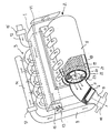
- the figure schematically shows a perspective view of a diesel engine with an exhaust system and an exhaust gas recirculation.
- the diesel engine illustrated in the figure comprises a schematically illustrated engine block 1, which is provided on the output side with an exhaust system 2 and on the input side with intake manifold 3 for intake of an air / exhaust gas mixture.
- engine block 1 In order to keep the presentation clear, details of the engine block 1 and in particular a diesel supply and distribution have not been shown.
- the exhaust system 2 in the example shown here consists of five outlet ports 4, which can also be referred to as manifolds, via which exhaust gas from the individual cylinders, not shown, is passed into a device 5 for soot combustion and exhaust gas purification. From there, the exhaust gas passes through a cleaning filter 6 in an exhaust pipe 7 to a branch 8, to which on the one hand an exhaust gas recirculation pipe 9 and on the other hand a flange 10 is connected for connection to an exhaust system, not shown.
- the five intake manifolds 3 are connected on the one hand via an air filter 11, which is shown schematically as a broken line, to a first and second air intake manifold 12, 13 and, on the other hand, to an exhaust manifold 14, so that a mixture of the intake air and the supplied air is drawn into the intake manifold 3 Exhaust takes place.
- an air filter 11 which is shown schematically as a broken line
- a first and a second controlled valve 15, 16 are arranged in the first and second air intake connections 13.
- a third controlled valve 17 is located in the exhaust gas recirculation pipe 9.
- the first and second valves 15, 16 are alternatively controlled, as will be described in detail below. To simplify the description, reference is therefore first made to the first valve 15 by way of example, the details described in this context correspondingly applying to the second valve 16.
- the first valve 15 and the third valve 17 are designed such that they form a two-way valve with constant flow. Opening or closing the first valve 15 therefore has a corresponding opposite effect of the third valve 17.
- the two-way valve can be realized in that the exhaust gas recirculation pipe 9 and the first air intake pipe 12 or the effective cross section of the two valves have the same diameter, that the first and third valves 15, 17 are each controlled by a throttle valve, and that the two throttle valves are coupled in opposite directions.
- the first and third valves 15, 17 are actuated mechanically via a lever and / or cable mimic (not shown) as a function of the position of the throttle valve, via which the engine speed is determined. This is achieved in a simple manner by connecting the lever and / or cable pull facial expressions to an accelerator pedal (not shown) with which the fuel supply or the throttle valve is controlled.
- the first and second valves can also be controlled as a function of the exhaust gas temperature in the exhaust gas recirculation pipe 9.
- the first valve 15 is closed and the third valve 17 is opened with decreasing speed. Conversely, with increasing speed, the first valve 15 is opened and the third valve 17 is closed.
- the flow in the first valve 15 is throttled to about 80% and correspondingly about 20% in the third valve 17 when the engine is started, idling or in overrun mode. In this operating state, the engine will have an exhaust gas / air mixture of 80:20 the intake manifold 3 supplied.
- the exhaust gas / air mixture can typically be 20:80.
- the regulated return of the exhaust gas results in a higher exhaust gas temperature at the outlet connection 4 and in the exhaust system 2. In this way, the burning off of soot particles in the device 5 is supported, since the exhaust gas temperatures can be increased up to the self-ignition temperature of the soot particles contained in the exhaust gas.
- the readiness for ignition can also be increased by a catalytic coating in the regeneration device 5.
- the combustion of the soot particles is achieved by the following structural design, which is visible through a partial cut of an outer housing cylinder 18
- the outlet ports 4 open tangentially into the housing 18, in which a hollow cylinder 19 is arranged coaxially to form an annular space 20 between the hollow cylinder 19 and the housing 18.
- the hollow cylinder consists of an outer layer of a perforated plate 21, an intermediate layer of wire mesh 22 underneath and an inner layer of a porous, catalytically coated material 23.
- the exhaust gas flows around the hollow cylinder 19 in the annular space 20 , wherein the soot particles heat up by friction on the perforated plate 21.
- the wire mesh 22 receives the temperature required for combustion.
- device 5 may also have other devices for burning soot.
- the cleaning filter 6 is also built up in layers.
- an insert made of perforated sheet metal there is a layer of wire mesh on the input side, which is followed by porous, catalytically coated material.
- a thermal sensor is present in the exhaust gas recirculation pipe 9, which regulates the exhaust gas / air mixture at a predetermined maximum temperature, which can be, for example, 300 ° C., in such a way that a further temperature increase is prevented .
- the first valve 15 is acted upon by a further thermal controller, which closes the first valve 15 and opens the second valve 16 when the temperature falls below a certain predetermined temperature, which then takes over the function of the first valve 15.
- This switchover is useful when the first air intake 12 is arranged in the direction of travel in front of the engine block 1, so that it sucks in air directly from the environment, which causes a corresponding reduction in the temperature of the exhaust gas / air mixture at low outside temperatures.
- the second air intake 13 is arranged behind the engine block 1 in the direction of travel. He can therefore only suck in air that has already warmed up on engine block 1.
- the function of the invention is described below using the example of an idling operation at an outside temperature that is below the minimum limit value, below which a switchover from the first suction point (first air suction nozzle 12) to the second air suction point (second air suction nozzle 13) takes place. Pre-heated air is therefore already sucked in. Since the accelerator pedal is completely withdrawn during idling, the second and third valves are driven in opposite phase in such a way that a maximum proportion of exhaust gas and a minimum proportion of air are conducted into the intake manifold 13. The exhaust gas / air mixture drawn in by the engine is therefore relatively hot, so that the exhaust gas in the outlet connection 4 has a temperature which is considerably higher than the exhaust gas temperature in engines without corresponding exhaust gas recirculation.
- the temperature is in the range of the self-ignition temperature of the soot particles contained in the exhaust gas.
- the exhaust system 2 is thus automatically regenerated.
- the catalytically coated material 23 can preferably consist of foam ceramic. The ignition readiness of the soot particles is increased even further if the hollow cylinder 19 is completely coated with catalytic material.
Landscapes
- Engineering & Computer Science (AREA)
- Chemical & Material Sciences (AREA)
- Combustion & Propulsion (AREA)
- Mechanical Engineering (AREA)
- General Engineering & Computer Science (AREA)
- Physics & Mathematics (AREA)
- Fluid Mechanics (AREA)
- Analytical Chemistry (AREA)
- Exhaust-Gas Circulating Devices (AREA)
- Exhaust Gas After Treatment (AREA)
- Output Control And Ontrol Of Special Type Engine (AREA)
Applications Claiming Priority (2)
| Application Number | Priority Date | Filing Date | Title |
|---|---|---|---|
| DE19873734470 DE3734470A1 (de) | 1987-10-12 | 1987-10-12 | Abgasrueckfuehrung an einem dieselmotor |
| DE3734470 | 1987-10-12 |
Publications (2)
| Publication Number | Publication Date |
|---|---|
| EP0312033A2 true EP0312033A2 (fr) | 1989-04-19 |
| EP0312033A3 EP0312033A3 (fr) | 1990-03-14 |
Family
ID=6338151
Family Applications (1)
| Application Number | Title | Priority Date | Filing Date |
|---|---|---|---|
| EP88116966A Withdrawn EP0312033A3 (fr) | 1987-10-12 | 1988-10-12 | Recirculation de gaz d'echappement pour moteur diesel |
Country Status (2)
| Country | Link |
|---|---|
| EP (1) | EP0312033A3 (fr) |
| DE (1) | DE3734470A1 (fr) |
Cited By (2)
| Publication number | Priority date | Publication date | Assignee | Title |
|---|---|---|---|---|
| FR2869648A1 (fr) * | 2004-04-30 | 2005-11-04 | Renault Sas | Moteur a combustion comportant un dispositif commande de decrassage du circuit de recirculation des gaz d'echappement |
| DE102014218409A1 (de) * | 2014-09-15 | 2016-03-17 | Robert Bosch Gmbh | Verfahren zum Betreiben einer Antriebseinrichtung und entsprechende Antriebseinrichtung |
Families Citing this family (1)
| Publication number | Priority date | Publication date | Assignee | Title |
|---|---|---|---|---|
| DE4120196A1 (de) * | 1991-06-19 | 1992-12-24 | Audi Ag | Vorrichtung zum erfassen der abgasrueckfuehrrate an einer brennkraftmaschine |
Family Cites Families (6)
| Publication number | Priority date | Publication date | Assignee | Title |
|---|---|---|---|---|
| US1552819A (en) * | 1920-08-13 | 1925-09-08 | Alanson P Brush | Internal-combustion engine |
| FR858037A (fr) * | 1939-03-28 | 1940-11-15 | Andre Citroe N | Procédé et dispositif pour l'amélioration du fonctionnement et du rendement des moteurs à injection |
| CH221394A (fr) * | 1941-03-24 | 1942-05-31 | W Blanc | Procédé d'alimentation d'un moteur à combustion interne et installation pour la mise en oeuvre de ce procédé. |
| DE1143672B (de) * | 1960-12-24 | 1963-02-14 | Maschf Augsburg Nuernberg Ag | Luftverdichtende selbstzuendende Einspritzbrennkraftmaschine mit einer durch einen Temperaturfuehler geregelten Rueckfuehrung von Abgasen in das Ansaugsystem |
| DE3007927C2 (de) * | 1980-03-01 | 1985-08-29 | Daimler-Benz Ag, 7000 Stuttgart | Mit homogenem Gas betriebene, fremdgezündete Brennkraftmaschine |
| DE3235953A1 (de) * | 1982-09-29 | 1984-03-29 | Robert Bosch Gmbh, 7000 Stuttgart | Verfahren und vorrichtung zur entfernung von festen bestandteilen aus dem abgas von brennkraftmaschinen, insbesondere von russbestandteilen |
-
1987
- 1987-10-12 DE DE19873734470 patent/DE3734470A1/de active Granted
-
1988
- 1988-10-12 EP EP88116966A patent/EP0312033A3/fr not_active Withdrawn
Cited By (2)
| Publication number | Priority date | Publication date | Assignee | Title |
|---|---|---|---|---|
| FR2869648A1 (fr) * | 2004-04-30 | 2005-11-04 | Renault Sas | Moteur a combustion comportant un dispositif commande de decrassage du circuit de recirculation des gaz d'echappement |
| DE102014218409A1 (de) * | 2014-09-15 | 2016-03-17 | Robert Bosch Gmbh | Verfahren zum Betreiben einer Antriebseinrichtung und entsprechende Antriebseinrichtung |
Also Published As
| Publication number | Publication date |
|---|---|
| DE3734470C2 (fr) | 1990-04-12 |
| DE3734470A1 (de) | 1989-04-20 |
| EP0312033A3 (fr) | 1990-03-14 |
Similar Documents
| Publication | Publication Date | Title |
|---|---|---|
| DE69205389T2 (de) | Einrichtung zur Minderung von Stickoxiden in Rauchgasen aus Brennkraftmaschinen. | |
| EP0532031B1 (fr) | Dispositif pour la régénération thermique de filtres à particules pour les gaz d'échappement de moteurs diesel | |
| DE69812270T2 (de) | Brennkraftmaschine mit einem Verbrennungsheizgerät | |
| EP1643094A1 (fr) | Système d'échappement d'un moteur à combustion interne et procédé correspondent pour le faire fonctionner | |
| DE102015108223B4 (de) | AGR-System mit Partikelfilter und Wastegate | |
| DE2322057A1 (de) | Vorrichtung zum katalytischen nachverbrennen von abgasen einer mehrzylindrigen brennkraftmaschine | |
| EP1455078B1 (fr) | Moteur à combustion interne ayant un turbocompresseur et un système de recyclage des gaz d'échappement | |
| EP0826868A1 (fr) | Méthode de purification de gaz d'échappement de moteurs à combustion interne | |
| EP0422432A1 (fr) | Procédé de traitement des gaz d'échappement d'un moteur à combustion interne | |
| DE19833619A1 (de) | Abgasanlage für aufgeladene Brennkraftmaschinen | |
| DE102017103560B4 (de) | Verbrennungsmotor und Verfahren zur Regeneration eines Partikelfilters im Abgaskanal eines Verbrennungsmotors | |
| EP0716221B1 (fr) | Moteur à combustion interne aves deux rangées de cylindres | |
| DE10130633A1 (de) | Verfahren zur Regenerierung eines Partikelfilters | |
| EP3667056B1 (fr) | Traitement des gaz d'échappement d'un moteur à combustion interne | |
| DE102018009400A1 (de) | Verbrennungskraftmaschine für ein Kraftfahrzeug mit einem in einem Abgastrakt angeordneten Brenner, sowie Verfahren zum Betreiben einer solchen Verbrennungskraftmaschine | |
| EP4244471B1 (fr) | Moteur à combustion interne pour véhicule motorisé, en particulier pour voiture | |
| DE3602038C1 (de) | Verfahren und Vorrichtung zur Regenerierung eines Dieselrussfilters | |
| DE3734470C2 (fr) | ||
| DE2438840A1 (de) | Thermischer reaktor | |
| DE102019005155A1 (de) | Verbrennungskraftmaschine für ein Kraftfahrzeug, insbesondere für einen Kraftwagen, sowie Verfahren zum Betreiben einer solchen Verbrennungskraftmaschine | |
| DE102017102874A1 (de) | Abgasnachbehandlungsanlage eines Verbrennungsmotors und Verfahren zur Beladung und/oder Regeneration von Partikelfiltern | |
| DE102012101767B4 (de) | Verbrennungskraftmaschine | |
| DE69722260T2 (de) | Vorrichtung und verfahren zum reduzieren der abgasemissionen in systemen mit katalytischen konvertern | |
| DE102019211114A1 (de) | Abgasnachbehandlungssystem und Verfahren zur Abgasnachbehandlung eines Verbrennungsmotors | |
| DE19939988A1 (de) | Verfahren zum Betreiben eines Dieselmotors |
Legal Events
| Date | Code | Title | Description |
|---|---|---|---|
| PUAI | Public reference made under article 153(3) epc to a published international application that has entered the european phase |
Free format text: ORIGINAL CODE: 0009012 |
|
| AK | Designated contracting states |
Kind code of ref document: A2 Designated state(s): AT BE CH DE ES FR GB GR IT LI LU NL SE |
|
| PUAL | Search report despatched |
Free format text: ORIGINAL CODE: 0009013 |
|
| AK | Designated contracting states |
Kind code of ref document: A3 Designated state(s): AT BE CH DE ES FR GB GR IT LI LU NL SE |
|
| 17P | Request for examination filed |
Effective date: 19900201 |
|
| 17Q | First examination report despatched |
Effective date: 19910723 |
|
| STAA | Information on the status of an ep patent application or granted ep patent |
Free format text: STATUS: THE APPLICATION IS DEEMED TO BE WITHDRAWN |
|
| 18D | Application deemed to be withdrawn |
Effective date: 19911202 |