EP0312318A2 - Tête d'impression par points - Google Patents
Tête d'impression par points Download PDFInfo
- Publication number
- EP0312318A2 EP0312318A2 EP88309521A EP88309521A EP0312318A2 EP 0312318 A2 EP0312318 A2 EP 0312318A2 EP 88309521 A EP88309521 A EP 88309521A EP 88309521 A EP88309521 A EP 88309521A EP 0312318 A2 EP0312318 A2 EP 0312318A2
- Authority
- EP
- European Patent Office
- Prior art keywords
- armature
- supporting parts
- torsion bar
- armatures
- elastic portions
- Prior art date
- Legal status (The legal status is an assumption and is not a legal conclusion. Google has not performed a legal analysis and makes no representation as to the accuracy of the status listed.)
- Withdrawn
Links
Images



Classifications
-
- B—PERFORMING OPERATIONS; TRANSPORTING
- B41—PRINTING; LINING MACHINES; TYPEWRITERS; STAMPS
- B41J—TYPEWRITERS; SELECTIVE PRINTING MECHANISMS, i.e. MECHANISMS PRINTING OTHERWISE THAN FROM A FORME; CORRECTION OF TYPOGRAPHICAL ERRORS
- B41J2/00—Typewriters or selective printing mechanisms characterised by the printing or marking process for which they are designed
- B41J2/485—Typewriters or selective printing mechanisms characterised by the printing or marking process for which they are designed characterised by the process of building-up characters or image elements applicable to two or more kinds of printing or marking processes
- B41J2/505—Typewriters or selective printing mechanisms characterised by the printing or marking process for which they are designed characterised by the process of building-up characters or image elements applicable to two or more kinds of printing or marking processes from an assembly of identical printing elements
-
- B—PERFORMING OPERATIONS; TRANSPORTING
- B41—PRINTING; LINING MACHINES; TYPEWRITERS; STAMPS
- B41J—TYPEWRITERS; SELECTIVE PRINTING MECHANISMS, i.e. MECHANISMS PRINTING OTHERWISE THAN FROM A FORME; CORRECTION OF TYPOGRAPHICAL ERRORS
- B41J2/00—Typewriters or selective printing mechanisms characterised by the printing or marking process for which they are designed
- B41J2/22—Typewriters or selective printing mechanisms characterised by the printing or marking process for which they are designed characterised by selective application of impact or pressure on a printing material or impression-transfer material
- B41J2/23—Typewriters or selective printing mechanisms characterised by the printing or marking process for which they are designed characterised by selective application of impact or pressure on a printing material or impression-transfer material using print wires
- B41J2/27—Actuators for print wires
- B41J2/28—Actuators for print wires of spring charge type, i.e. with mechanical power under electro-magnetic control
-
- B—PERFORMING OPERATIONS; TRANSPORTING
- B41—PRINTING; LINING MACHINES; TYPEWRITERS; STAMPS
- B41J—TYPEWRITERS; SELECTIVE PRINTING MECHANISMS, i.e. MECHANISMS PRINTING OTHERWISE THAN FROM A FORME; CORRECTION OF TYPOGRAPHICAL ERRORS
- B41J2/00—Typewriters or selective printing mechanisms characterised by the printing or marking process for which they are designed
- B41J2/22—Typewriters or selective printing mechanisms characterised by the printing or marking process for which they are designed characterised by selective application of impact or pressure on a printing material or impression-transfer material
- B41J2/23—Typewriters or selective printing mechanisms characterised by the printing or marking process for which they are designed characterised by selective application of impact or pressure on a printing material or impression-transfer material using print wires
- B41J2/235—Print head assemblies
Definitions
- the present invention relates to an impact dot print head comprising styluses for a dot matrix printer and, more particularly, to an impact dot print head of a release type in which each one of armatures respectively fixedly holding styluses is attracted resiliently to a core by the magnetism of a permanent magnet, a solenoid corresponding to a selected stylus is energized to cancel the magnetism of the permanent magnet to release the armature from the core so that the stylus is allowed to advance for printing a dot.
- an armature 50 is disposed between supporting parts 51, a torsion bar 52 is inserted in through holes 53 formed through the supporting parts 51 and the armature 50, and a brazing filler metal filled in brazing holes 54 formed in the armature 50 and the supporting parts 51 so as to be connected respectively to the middle portions of the through holes 53 is melted to braze the torsion bar 52 to the armature 50 and the supporting parts 51.
- the diameter of the through holes 53 must be on the order of 1 mm and that of the brazing holes 54 must be still smaller. Boring such small holes in the armature 50 and the supporting parts 51 and filler the brazing filler metal in the brazing holes 54 are difficult. Furthermore, the brazing filler metal is liable to flow over the elastic portions 55 of the torsion bar 52 when molten adversely affecting the twisting action of the elastic portions 55.
- the width W of the armature 50 and the supporting parts 51 must be sufficiently large, and the width W must be greater than a value necessary for forming a magnetic path across the armature 50 and a corresponding core.
- the axial length L of the elastic portions 55 of the torsion bar 52 must be large and, to return the armature 50 at a high speed to its standby position, the elastic portions 55 must have a sufficiently large diameter.
- the axial length L of the elastic portions 55 must be sufficiently large to limit the stress in the elastic portions 55 of the torsion bar 52 to an optional magnitude and to secure an optional strength of the elastic portions 55 of the torsion bar 52.
- the construction of the print head having an arrangement of a plurality of armatures 50 is enlarged when the width W of the armature 50 and the supporting parts 51 and/or the length L of the elastic portions 55 is increased, it is difficult to limit the stress in the elastic portions 55 to a desired value and to provide the elastic portions 55 with a desired strength.
- a dot print head supporting parts, and an armature disposed between the supporting parts and opposite a core fitted in a solenoid are connected by a torsion bar having elastic portions extending on the opposite sides of the armature, and the armature is turned by varying magnetic flux to advance a stylus fixedly held on the armature toward a platen for printing, the torsion bar is fitted at least in either the armature or the supporting parts, open grooves for containing a brazing filler metal are formed in the armature and the supporting parts, and flanges are formed on the torsion bar at the opposite ends of the elastic portions so as to be contiguous with the side surfaces of the supporting parts and the armature, respectively.
- the torsion bar is fitted in the grooves, the brazing filler metal is filled in the grooves, and then the brazing filler metal is melted to braze the torsion bar to the supporting parts and the armature.
- the number of machined portions is reduced by half since the grooves receive both the torsion bar and the brazing filler metal, the flanges facilitate axially positioning the torsion bar with respect to the supporting parts and prevents the flow of the brazing filler metal over the elastic portions of the torsion bar, and the brazing strength is increased since the area of contact surfaces of the torsion bar in contact with the brazing filler metal is increased.
- an armature fixedly holding a stylus at the free end thereof is disposed opposite a core fitted in a solenoid, with the base end thereof positioned between supporting parts with predetermined gaps between the opposite sides thereof and the corresponding side surfaces of the supporting parts, open grooves for receiving a torsion bar having elastic portions to be extended on the opposite sides of the armature are formed respectively in the base end of the armature and the supporting parts, either the width of the base end of the armature or the width of the supporting parts is reduced to form increased gaps between the opposite side surfaces of the base end of the armature and the corresponding side surfaces of the supporting parts so that a torsion bar having elastic portions having an increased axial length can be employed, and flanges are formed on the torsion bar so as to be in contact with the side surfaces of the base end of the armature.
- the torsion bar is fitted in the grooves, a brazing filler metal is put in the grooves, and then the brazing filler metal is melted to braze the torsion bar to the armature and the supporting parts. Since the width of the base end of the armature or the width of the supporting parts is reduced to form sufficiently large gaps between the opposite side surfaces of the base end of the armature and the corresponding side surfaces of the supporting parts, the elastic portions of the torsion bar can be formed in a sufficiently large axial length.
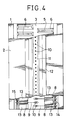
- an upper yoke 2 is joined to the open end of a lower yoke 1 having a U-shaped cross section.
- a permanent magnet 3 is extended on the inner bottom surface of the lower yoke 1.
- a plurality of solenoids 7 are mounted respectively on a plurality of cores 6 each having a foot 4 fixed to the permanent magnet 3, and a standing portion 5.
- An armature 8 disposed opposite the core 6 has a plate-shaped arm 9 projecting from the free end of the body thereof, and a stylus 10 is fixed to the extremity of the arm 9.
- a stylus guide 11 for slidably guiding the styluses 10 is fixed to a nose 12 fixed to the upper yoke 2.
- Projections 13 and supporting parts 14 are formed integrally with the upper yoke 2 on the inner surface of the latter.
- Each armature 8 is disposed between the adjacent projections 13 and is connected to the supporting parts 14 by a torsion bar 15.
- a plurality of dot print units each comprising the core 6, the solenoid 7 and the armature 8 are arranged zigzag in two straight rows.
- the dot print units may be arranged in a circular arrangement.
- the torsion bar 15 is placed in U-shaped grooves 16 respectively formed in the armature 8 and the supporting parts 14.
- the torsion bar 15 is formed of an elastic low-carbon nickel-rich alloy steel.
- the torsion bar 15 has elastic portions 18 having a small diameter and extending on the opposite sides of the armature 8, and flanges 17 formed at the opposite ends of the elastic portions 18 so as to be contiguous respectively with the side surfaces of the armature 8 and those of the supporting parts 14.
- a brazing filler metal, not shown, filled in the grooves 16 is melted to braze the torsion bar 15 to the armature 8 and the supporting parts 14.
- the armature 8 In brazing the torsion bar 15 to the armature 8 and the supporting parts 14, the armature 8 is separated from the end surface (attracting surface) of the standing body 5 of the core 6. When the dot print head is assembled, the armature 8 is attracted to the core 6 by the magnetism of the permanent magnet 3 against the torsional resilience of the elastic portions 18 of the torsion bar 15.
- the cores 6 are fixed to the permanent magnet, magnetic paths of a short length are formed individually between the permanent magnet and the armatures, respectively. Since the cores 6 are arranged zigzag at regular intervals in two straight rows, leakage of magnetic flux, and magnetic interference between the adjacent cores 6 are prevented. Furthermore, since the area of surface of the foot 4 of the core 6 in contact with the permanent magnet is greater than the area of end surface of the standing portion 5 of the same, the magnetism of the permanent magnet 3 can be used effectively and magnetic flux density in the end surface of the standing portion 5 of the core 6 is increased to apply a high magnetic attraction to the armature 8.
- dot pitch on a vertical line perpendicular to the axis of the platen can be adjusted by mounting the dot print head with yokes 1 and 2 at an inclination on a carriage which reciprocates along the platen so that the styluses 10 are arranged respectively on straight lines inclined slightly to a vertical line perpendicular to the horizontal axis of the platen. Since the leakage of magnetic flux and magnetic interference between the adjacent cores 6 can be prevented, any one of the solenoids can be energized at an optional moment, and thereby the dot pitch along the axis of the platen can be adjusted to an optional value.
- the brazing filler metal is filled in the grooves 16 for receiving the torsion bar 15, no particular machining operation is necessary for forming holes or grooves for containing the brazing filler metal.
- the flanges 17 of the torsion bar 15 facilitates the axial positioning of the torsion bar 15, prevents the flow of the molten brazing filler metal over the elastic portions 18, and increases the area of contact of the brazing filler metal with the torsion bar 15 to enhance the brazing strength.
- the torsion bar 15 may be provided fixedly beforehand and the grooves 16 may be formed only in the supporting parts 14. On the contrary, the torsion bar 15 may be provided fixedly on the supporting parts 14 and the groove 16 may be formed only in the armature 8.
- the grooves for receiving the torsion bar is used also for containing the brazing filler metal, nor particular machining operation is necessary for forming holes or grooves for containing the brazing filler metal, and thereby steps of manufacturing process is reduced. Furthermore, since the flanges of the torsion bar is formed so as to be contiguous with the side walls of the armature and the supporting parts, the axial positioning of the torsion bar is facilitated and the flow of the brazing filler metal over the elastic portions is prevented, and the area of surface of the torsion bar in contact with the brazing filler metal is increased to enhance the brazing strength.
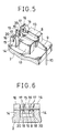
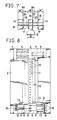
- a dot print head in a second embodiment according to the present invention will be described hereinafter with reference to Figs. 5 to 9, in which parts like or corresponding to those of the first embodiment are denoted by the same reference numerals.
- An upper yoke 2 is joined to the open end of a U-shaped lower yoke 1.
- a permanent magnet 3 is extended on the inner bottom surface of the lower yoke 1.
- a plurality of solenoids 7 are mounted respectively on a plurality of cores 6 each having a foot 4 fixed to the permanent magnet 3, and a standing body 5.
- An armature 8 disposed opposite the core 6 has a plate-shaped arm 9 projecting from the free end of the body thereof, and a stylus 10 is fixed to the extremity of the arm 9.
- a stylus guide 11 for slidably guiding the styluses 10 is held on a nose 12 fixed to the upper yoke 2.
- Projections 13 and supporting parts 14 are formed integrally with the upper yoke 2 on the inner surface of the latter.
- Each armature 8 is disposed between the adjacent projections 13 and is connected to the supporting parts 14 by a torsion bar 15.
- an upper portion, as viewed in Fig. 8, of the upper yoke 2 is partially cut away and the solenoids 7 are omitted to show the arrangement of the cores 6, and a lower portion, as viewed in Fig. 8, of the upper yoke 2 is partially cutaway to show the arrangement of the armature 8, the projections 13 and the supporting parts 14.
- a plurality of dot print units each comprising the core 6, the solenoid 7 and the armature 8 are arranged zigzag in two straight rows.
- the dot print units may be arranged in a circular arrangement.
- each armature 8 has a main portion for forming part of a magnetic path in combination with the th core 6, having a width W, and a base end 19 having a width W′ smaller than the width W of the main portion, and each supporting part 14 has a width W ⁇ smaller than the width W of the main portion of the armature 8, so that comparatively large gaps 20 are formed between the opposite side surfaces of the base end 19 of the armature 8 and the corresponding side surfaces of the supporting parts 14, respectively.
- a torsion bar 15 is placed in U-shaped grooves respectively formed in the armature 8 and the supporting parts 14.
- the torsion bar 15 is formed of an elastic low-carbon nickel-rich alloy steel, has elastic portions 18 extending on the opposite sides of the base end 19 of the armature 8, and is provided integrally with flanges flanges 17 contiguous with the opposite side surfaces of the base end 19 of the armature 8 and the side surfaces of the supporting parts 14, respectively.
- a brazing filler metal, not shown, filled in the grooves 16 is melted to braze the torsion bar 15 to the armature 8 and the supporting parts 14.
- the armature 8 In brazing the torsion bar 15 to the armature 8 and the supporting parts 14, the armature 8 is separated from the end surface (attracting surface) of the standing body 5 of the core 6.
- the armature 8 is attracted to the core 6 by the magnetism of the permanent magnet 3 against the torsional resilience of the elastic portions 18 of the torsion bar 15.
- the comparatively large gaps 20 are formed by forming the base end of each armature 8 and each supporting part 14 respectively in the comparatively small widths W′ and W ⁇ to enable the elastic portions of each torsion bar 15 to be formed in a sufficiently large length L. Accordingly, stress in the elastic portions 18 and the strength of the same can optionally be adjusted.
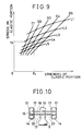
- Fig. 9 shows the relation between the strength of the elastic portion 18 and stress in the elastic portion 18 for the length of the elastic portion 18.
- L1, L2, L3, L4 and L5 are lengths of the elastic portion 18, D1, D2, D3, D4 and D5 are diameters of the elastic portion 18, in which L1 ⁇ L2 ⁇ L3 ⁇ L4 ⁇ L5, and D1 ⁇ D2 ⁇ D3 ⁇ D4 ⁇ L5.
- a desired strength of the elastic portion is F0 and a desired stress in the elastic portion is ⁇ 0. Then, the stress is nearly equal to the desired stress whereas the strength is insufficient when the diameter is D1 and the length is L2.
- the strength is sufficient whereas the stress is excessively large.
- the length is L3 and the diameter is D3, the strength and the stress are equal to the desired strength and the desired stress, respectively.
- the stress in the elastic portion 18 exceeds the desired stress. Accordingly, when the elastic portion 18 has a sufficient length, such as the length L5, the diameter of the elastic portion 8 can be selected from diameters in a comparatively wide range of diameter without causing the stress to increase beyond the desired stress ⁇ 0.
- the width W′ of the base end of the armature 8 and the width W ⁇ of the supporting parts 14 are comparatively small, the area of brazing surface is increased by the flanges 17 of the torsion bar 15 to secure sufficient strength in brazing the torsion bar 15 to the supporting parts 14.
- the dot print head can be formed in a further small size by disposing the armatures 8 and the supporting parts 14 respectively in comparatively small spaces.
- the thickness Wt of the flange 17 meets inequalities: 2Wt ⁇ W - W′ and Wt ⁇ W - W ⁇
- the length of the elastic portions 18 can be increased while the length of the torsion bar 15 and the distance between the respective outer side surfaces of the adjacent supporting parts 14 are reduced, which enables the armatures 8 to be arranged at a reduced pitch to curtail the size of the dot print head.
- the thickness of the flanges 17 can be reduced without entailing problem in the strength of the torsion bar 15 because no thrust force acts on the torsion bar 15.
- the effect of flanges having a comparatively small thickness on preventing the flow of the brazing filler metal over the elastic portions 18 is the same as that of flanges having a comparatively large thickness.
- brazing strength in brazing the torsion bar 15 to the supporting parts 14 14 is further increased, and hence the width of the supporting parts 14 can further be reduced, which enables the further increase in the length of the elastic portions 18 or the further reduction in the space in which the armatures 8 and the supporting parts 14 are arranged.
- the width W of the supporting parts 14 is equal to the width W of the main body of an armature 8, and the width of the base end of the armature 8 is is reduced to W′ smaller than the width W of the main body of the same to secure comparatively large gaps 20 between the base end of the armature 8 and the supporting parts 14 so that a torsion bar 15 having elastic portions 18 having a necessary length L can be used and the armatures 8 and the supporting parts 14 can be arranged in a comparatively small space.
- each elastic portion 18 of a torsion bar 15 is increased by a length equal to the difference between half of the difference between the width W of the main body of an armature 8 and the width W′ of the base end of the armature 8, and the thickness Wt of a flange 17 of the torsion bar 15, and hence the length L′ of the elastic portion is greater than the length L of the elastic portion 18 in the second embodiment.
- the strength of the elastic portion 18 of the torsion bar 15 in the third embodiment is increased, the elastic portion 18 has sufficient durability, stress in the elastic portion 18 is reduced, and the torsion bar 15 in the third embodiment enables the armature 8 to operate at a high speed.
- An armature 8 has a main body and a base end having the same width W while supporting portions 14 have a reduced width W′, so that gaps 20 having a necessary width are formed between the armature 8 and the supporting parts 14, a torsion bar 15 having elastic portions 18 having a sufficient length L can be employed, and the armatures 8 and the supporting parts 14 can be arranged in a reduced space.
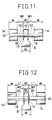
- Flanges 17 are formed in the torsion bar 15 so as to be contiguous with the inner side surfaces of the supporting parts 14 (Fig. 13), with the outer side surfaces of the supporting parts 14 (Fig. 14) or with the respective inner and outer surfaces of the supporting parts 14 (Fig. 15) so that the thickness of the supporting parts 14 can further be reduced, to secure sufficient brazing strength in brazing the torsion bar 15 to the supporting parts 14.
- FIG. 16 Shown in Fig. 16 is a modification of the construction shown in Fig. 12, in which the width W ⁇ of supporting portions 14 is smaller than the width W of the supporting portions 14 in Fig. 12 to increase the width of a gap 20 between the side surface of an armature 8 and the inner side surface of the corresponding supporting member 14, so that the length L′ of the elastic portion 18 of a torsion bar 15 is increased accordingly relative to the length L of the elastic portion 18 of the torsion bar 15 of Fig. 12.
- flanges 17 are formed in a torsion bar 15 so as to be contiguous with the respective opposite side surfaces of an armature 8 and the supporting parts 14, only one of the supporting parts 14 is disposed between the adjacent armatures 8 to support both the adjacent ends of the adjacent torsion bars 15 so that the length of the elastic portions 18 of the torsion bars 15 is increased and the space for arranging the armatures 8 and the supporting parts 14 can effectively be reduced.
- a single torsion bar 15 is supported on a plurality of supporting parts 14 to support a plurality of armatures 8, which enables the further reduction of the width of the supporting parts 14.
- the torsion bar is placed in the grooves formed in the supporting parts and the armature and is brazed to the supporting parts and the armature to connect the armature and the supporting parts by the torsion bar.
- a comparatively wide gap is formed between the armature and the supporting part by reducing the width of the base end of the armature of that of the supporting part. Accordingly, the elastic portions can be formed in the torsion bar in a sufficiently large axial length, and hence the stress in the elastic portions and the strength of the elastic portions can optionally be determined.
- the flanges are formed on the torsion bar so as to be contiguous with the side surfaces of the armature and/or those of the supporting parts, a sufficiently large brazing strength can be secured in brazing the torsion bar to the armature and the supporting parts even if the width of the armature and/or that of the supporting parts is reduced.
- the reduction in the width of the armature and/or that of the supporting parts enables the reduction in size of the dot print head through the reduction of a space for arranging the armatures and the supporting parts.
Landscapes
- Impact Printers (AREA)
Applications Claiming Priority (4)
| Application Number | Priority Date | Filing Date | Title |
|---|---|---|---|
| JP260699/87 | 1987-10-15 | ||
| JP62260699A JPH01101162A (ja) | 1987-10-15 | 1987-10-15 | ドツトプリンタヘツド |
| JP2087/88 | 1988-01-08 | ||
| JP63002087A JPH01178453A (ja) | 1988-01-08 | 1988-01-08 | ドツトプリンタヘツド |
Publications (2)
| Publication Number | Publication Date |
|---|---|
| EP0312318A2 true EP0312318A2 (fr) | 1989-04-19 |
| EP0312318A3 EP0312318A3 (fr) | 1989-09-13 |
Family
ID=26335410
Family Applications (1)
| Application Number | Title | Priority Date | Filing Date |
|---|---|---|---|
| EP88309521A Withdrawn EP0312318A3 (fr) | 1987-10-15 | 1988-10-12 | Tête d'impression par points |
Country Status (3)
| Country | Link |
|---|---|
| US (1) | US4925625A (fr) |
| EP (1) | EP0312318A3 (fr) |
| KR (1) | KR920000972B1 (fr) |
Families Citing this family (1)
| Publication number | Priority date | Publication date | Assignee | Title |
|---|---|---|---|---|
| DE68911375T2 (de) * | 1988-05-25 | 1994-07-14 | Seiko Epson Corp | Punktdruckkopf für Anschlagdrucker. |
Family Cites Families (10)
| Publication number | Priority date | Publication date | Assignee | Title |
|---|---|---|---|---|
| JPS5516834B2 (fr) * | 1971-11-20 | 1980-05-07 | ||
| GB1478498A (en) * | 1975-09-12 | 1977-06-29 | Post Office | Joining metal surfaces |
| JPS5235736A (en) * | 1975-09-16 | 1977-03-18 | Kobe Steel Ltd | Method of brazing joint in heat exchangers without flux |
| SU570464A1 (ru) * | 1975-10-27 | 1977-08-30 | Предприятие П/Я Р-6930 | Способ пайки телескопических соединений |
| JPS54120257A (en) * | 1978-03-11 | 1979-09-18 | Yoshiaki Kawada | Stainless steel pipe connecting apparatus and method |
| JPS588665A (ja) * | 1981-07-10 | 1983-01-18 | Ricoh Co Ltd | インク式ドツトプリンタ |
| JPS60147A (ja) * | 1983-06-15 | 1985-01-05 | Fujitsu Ltd | 制御信号通信方式 |
| US4634301A (en) * | 1983-10-20 | 1987-01-06 | Nippon Telecommunication Engineering Company | Print head with torsion spring |
| JPS6144656A (ja) * | 1984-08-10 | 1986-03-04 | Brother Ind Ltd | ドツトプリンタ用プリントヘツド |
| JPS61121958A (ja) * | 1984-11-20 | 1986-06-09 | Brother Ind Ltd | ドツトプリンタ用プリントヘツド |
-
1988
- 1988-10-12 EP EP88309521A patent/EP0312318A3/fr not_active Withdrawn
- 1988-10-12 KR KR1019880013306A patent/KR920000972B1/ko not_active Expired
- 1988-10-14 US US07/257,883 patent/US4925625A/en not_active Expired - Fee Related
Also Published As
| Publication number | Publication date |
|---|---|
| EP0312318A3 (fr) | 1989-09-13 |
| KR920000972B1 (ko) | 1992-01-31 |
| KR890006396A (ko) | 1989-06-13 |
| US4925625A (en) | 1990-05-15 |
Similar Documents
| Publication | Publication Date | Title |
|---|---|---|
| US4976554A (en) | Release-type dot print head and method of manufacturing the same | |
| EP0005640A1 (fr) | Imprimante à fil électromagnétique | |
| US4925625A (en) | Dot print head having a torsion bar with elastic portions | |
| EP0110662B1 (fr) | Tête d'impression par points | |
| JPH0722994B2 (ja) | ドットプリンタヘッドの組立方法 | |
| US4572681A (en) | Wire dot print head | |
| US4652158A (en) | Armature support device for torsion spring print head | |
| CA1217678A (fr) | Tete d'impression matricielle par points | |
| EP0114744B1 (fr) | Tête d'impression par points | |
| JPS6168255A (ja) | ドツトプリンタヘツドの製造方法 | |
| CA1203430A (fr) | Solenoide d'imprimante | |
| US4634301A (en) | Print head with torsion spring | |
| JPH0547649Y2 (fr) | ||
| JPH01178453A (ja) | ドツトプリンタヘツド | |
| JPH01101162A (ja) | ドツトプリンタヘツド | |
| US4944615A (en) | Permanent magnet print head assembly with a square magnet | |
| KR920009763B1 (ko) | 석방형 도트프린터헤드 | |
| JPH0547648Y2 (fr) | ||
| JPH0616756Y2 (ja) | ワイヤドット印字ヘッドのアーマチュア | |
| JPH01101163A (ja) | 釈放型ドツトプリンタヘツド | |
| US5651621A (en) | Wire dot print head with print wires fixed to tip portions of armatures differentiated in resiliency | |
| US5215389A (en) | Print head for a dot matrix printer | |
| JP2003145810A (ja) | ドットプリンタ及びそれに用いる印字ユニット交換冶具 | |
| JPH0556437U (ja) | 印字ワイヤアッセンブリ | |
| EP0269959A1 (fr) | Tête d'impression de type à fils |
Legal Events
| Date | Code | Title | Description |
|---|---|---|---|
| PUAI | Public reference made under article 153(3) epc to a published international application that has entered the european phase |
Free format text: ORIGINAL CODE: 0009012 |
|
| 17P | Request for examination filed |
Effective date: 19881018 |
|
| AK | Designated contracting states |
Kind code of ref document: A2 Designated state(s): DE FR GB |
|
| PUAL | Search report despatched |
Free format text: ORIGINAL CODE: 0009013 |
|
| AK | Designated contracting states |
Kind code of ref document: A3 Designated state(s): DE FR GB |
|
| 17Q | First examination report despatched |
Effective date: 19910703 |
|
| STAA | Information on the status of an ep patent application or granted ep patent |
Free format text: STATUS: THE APPLICATION HAS BEEN WITHDRAWN |
|
| 18W | Application withdrawn |
Withdrawal date: 19930108 |