EP0312355A2 - Dispositif de suspension pour ordinateurs personnels et écrans de visualisation - Google Patents
Dispositif de suspension pour ordinateurs personnels et écrans de visualisation Download PDFInfo
- Publication number
- EP0312355A2 EP0312355A2 EP88309600A EP88309600A EP0312355A2 EP 0312355 A2 EP0312355 A2 EP 0312355A2 EP 88309600 A EP88309600 A EP 88309600A EP 88309600 A EP88309600 A EP 88309600A EP 0312355 A2 EP0312355 A2 EP 0312355A2
- Authority
- EP
- European Patent Office
- Prior art keywords
- suspension system
- members
- suspension
- carriage
- monitor
- Prior art date
- Legal status (The legal status is an assumption and is not a legal conclusion. Google has not performed a legal analysis and makes no representation as to the accuracy of the status listed.)
- Granted
Links
Images

Classifications
-
- F—MECHANICAL ENGINEERING; LIGHTING; HEATING; WEAPONS; BLASTING
- F16—ENGINEERING ELEMENTS AND UNITS; GENERAL MEASURES FOR PRODUCING AND MAINTAINING EFFECTIVE FUNCTIONING OF MACHINES OR INSTALLATIONS; THERMAL INSULATION IN GENERAL
- F16M—FRAMES, CASINGS OR BEDS OF ENGINES, MACHINES OR APPARATUS, NOT SPECIFIC TO ENGINES, MACHINES OR APPARATUS PROVIDED FOR ELSEWHERE; STANDS; SUPPORTS
- F16M11/00—Stands or trestles as supports for apparatus or articles placed thereon ; Stands for scientific apparatus such as gravitational force meters
- F16M11/20—Undercarriages with or without wheels
- F16M11/2007—Undercarriages with or without wheels comprising means allowing pivoting adjustment
- F16M11/2021—Undercarriages with or without wheels comprising means allowing pivoting adjustment around a horizontal axis
-
- A—HUMAN NECESSITIES
- A47—FURNITURE; DOMESTIC ARTICLES OR APPLIANCES; COFFEE MILLS; SPICE MILLS; SUCTION CLEANERS IN GENERAL
- A47B—TABLES; DESKS; OFFICE FURNITURE; CABINETS; DRAWERS; GENERAL DETAILS OF FURNITURE
- A47B21/00—Tables or desks for office equipment, e.g. typewriters, keyboards
-
- F—MECHANICAL ENGINEERING; LIGHTING; HEATING; WEAPONS; BLASTING
- F16—ENGINEERING ELEMENTS AND UNITS; GENERAL MEASURES FOR PRODUCING AND MAINTAINING EFFECTIVE FUNCTIONING OF MACHINES OR INSTALLATIONS; THERMAL INSULATION IN GENERAL
- F16M—FRAMES, CASINGS OR BEDS OF ENGINES, MACHINES OR APPARATUS, NOT SPECIFIC TO ENGINES, MACHINES OR APPARATUS PROVIDED FOR ELSEWHERE; STANDS; SUPPORTS
- F16M11/00—Stands or trestles as supports for apparatus or articles placed thereon ; Stands for scientific apparatus such as gravitational force meters
- F16M11/02—Heads
- F16M11/04—Means for attachment of apparatus; Means allowing adjustment of the apparatus relatively to the stand
- F16M11/06—Means for attachment of apparatus; Means allowing adjustment of the apparatus relatively to the stand allowing pivoting
- F16M11/08—Means for attachment of apparatus; Means allowing adjustment of the apparatus relatively to the stand allowing pivoting around a vertical axis, e.g. panoramic heads
-
- F—MECHANICAL ENGINEERING; LIGHTING; HEATING; WEAPONS; BLASTING
- F16—ENGINEERING ELEMENTS AND UNITS; GENERAL MEASURES FOR PRODUCING AND MAINTAINING EFFECTIVE FUNCTIONING OF MACHINES OR INSTALLATIONS; THERMAL INSULATION IN GENERAL
- F16M—FRAMES, CASINGS OR BEDS OF ENGINES, MACHINES OR APPARATUS, NOT SPECIFIC TO ENGINES, MACHINES OR APPARATUS PROVIDED FOR ELSEWHERE; STANDS; SUPPORTS
- F16M11/00—Stands or trestles as supports for apparatus or articles placed thereon ; Stands for scientific apparatus such as gravitational force meters
- F16M11/20—Undercarriages with or without wheels
- F16M11/2092—Undercarriages with or without wheels comprising means allowing depth adjustment, i.e. forward-backward translation of the head relatively to the undercarriage
-
- F—MECHANICAL ENGINEERING; LIGHTING; HEATING; WEAPONS; BLASTING
- F16—ENGINEERING ELEMENTS AND UNITS; GENERAL MEASURES FOR PRODUCING AND MAINTAINING EFFECTIVE FUNCTIONING OF MACHINES OR INSTALLATIONS; THERMAL INSULATION IN GENERAL
- F16M—FRAMES, CASINGS OR BEDS OF ENGINES, MACHINES OR APPARATUS, NOT SPECIFIC TO ENGINES, MACHINES OR APPARATUS PROVIDED FOR ELSEWHERE; STANDS; SUPPORTS
- F16M13/00—Other supports for positioning apparatus or articles; Means for steadying hand-held apparatus or articles
- F16M13/02—Other supports for positioning apparatus or articles; Means for steadying hand-held apparatus or articles for supporting on, or attaching to, an object, e.g. tree, gate, window-frame, cycle
-
- F—MECHANICAL ENGINEERING; LIGHTING; HEATING; WEAPONS; BLASTING
- F16—ENGINEERING ELEMENTS AND UNITS; GENERAL MEASURES FOR PRODUCING AND MAINTAINING EFFECTIVE FUNCTIONING OF MACHINES OR INSTALLATIONS; THERMAL INSULATION IN GENERAL
- F16M—FRAMES, CASINGS OR BEDS OF ENGINES, MACHINES OR APPARATUS, NOT SPECIFIC TO ENGINES, MACHINES OR APPARATUS PROVIDED FOR ELSEWHERE; STANDS; SUPPORTS
- F16M2200/00—Details of stands or supports
- F16M2200/06—Arms
- F16M2200/068—Arms being part of the undercarriage
-
- Y—GENERAL TAGGING OF NEW TECHNOLOGICAL DEVELOPMENTS; GENERAL TAGGING OF CROSS-SECTIONAL TECHNOLOGIES SPANNING OVER SEVERAL SECTIONS OF THE IPC; TECHNICAL SUBJECTS COVERED BY FORMER USPC CROSS-REFERENCE ART COLLECTIONS [XRACs] AND DIGESTS
- Y10—TECHNICAL SUBJECTS COVERED BY FORMER USPC
- Y10S—TECHNICAL SUBJECTS COVERED BY FORMER USPC CROSS-REFERENCE ART COLLECTIONS [XRACs] AND DIGESTS
- Y10S248/00—Supports
- Y10S248/917—Video display screen support
- Y10S248/919—Adjustably orientable video screen support
- Y10S248/92—Angular and linear video display screen support adjustment
Definitions
- This invention relates generally to stands and supports for personal computers and the cathode ray tube (CRT) monitors used with those computers, and particularly to an apparatus for supporting a variety of personal computers and their monitors completely above a work surface while permitting the height, tilt angel, or rotation of that monitor to be fully adjusted, allowing access to the personal computer control panel and disk drives, and further allowing that monitor to be "parked” in a location adjacent to but displaced from the work surface.
- CTR cathode ray tube
- peripheral devices include extended keyboards, large-screen or multiple page monitors, a mouse or trackball, joysticks, digitizers such as image scanners or drawing pads, printers, modems, hard disks and optional format disk drives, coprocessors, power supplies, networking interfaces, and many other specialized devices such as musical keyboards.
- the average drafting work station will comprise a CPU with built in hard disk, one optional disk drive, keyboard, mouse, digitizer pad, and two monitors (one large screen).
- a standard desk top publishing work station might include a CPU, large screen monitor, laser printer, image scanner, keyboard, mouse, external hard disk, and disk drive.
- monitor stands which straddle a computer or CPU, with the separate monitor resting on top. Some monitors are designed so they may sit directly on the computer, or are themselves freestanding and can be turned in different directions to provide wide or full height viewing.
- Each of these monitor supports or stands present several common drawbacks when used in a work station or computer intensive environment.
- Swivel/Tilt Mounting Device for a Cathode Ray Tube disclosed in United States Patent No. 4,453,687.
- This Swivel/Tilt device has been adapted for use in supporting various personal computer systems in which the monitor, CPU, or disk drives are combined in a common housing, with the keyboard and mouse being attached by cables.
- Representative examples of such a device are currently marketed by Ergotron, Inc., of Minneapolis, Minnesota, under the name "MacTilt".
- Some monitor supports have extensible, cantilevered arms to support the monitor and permit it to be rotated, tilted, swiveled, raised and lowered to various positions.
- Representative examples of such extensible monitor supports include the "PC Float System” marketed by Global Computer Supplies, the “CRT Valet” marketed by Businessland of San Jose, California, and the “CRT Shuttle” also marketed by Global Computer Supplies and disclosed in United States Patent No. 4,562,987.
- the PC Float System has a pivotable arm which clamps to the lip of a desk and is supported by a pressurized pneumatic cylinder.
- the monitor platform is supported on a hemispherical globe resting within a basin. The globe, and thus the monitor platform and monitor, may be rotated within the torus to adjust the position of the monitor.
- the CRT Shuttle similarly clamps to a work surface and comprises a pair of jointed arms which permit an individual to manually raise or lower the monitor, or rotate it in several directions.
- the CRT Valet uses a cable biased cantilevered arm configuration which permits vertical and rotational movement of the monitor, as well as manual adjustment of the monitor position.
- Each of these extensible arm systems provides some advantages over conventional monitor stands. They permit the user some degree of immediate movement of the monitor without having to lift the monitor or unlock hardware fittings. Each permits the monitor to be parked in a position away from the normal viewing position, and allow multiple users to share a monitor if their desks are situated accordingly. Finally, they include such options as gripping handles, an electrical power outlet, and options to support other equipment.
- each requires that the main support arm be clamped to the lip of a desk with a mounting bracket or permanently attached to the desk if no lip is present.
- Each arm extends over the desk between the mounting bracket and the monitor, thus preventing the user from placing items in the area bounded by the sweep of the arm.
- the CRT Valet arm is jointed in the vertical direction
- the CRT Shuttle is jointed horizontally and the PC Float System is unjointed, thereby limiting any clearance between the work surface and arm, and consequently consuming more work area than the monitor alone.
- the ability to share a monitor is constrained by the extent to which the support arm will reach.
- each of the above extensible arm units allows the monitor to be parked when using a desk in an open area, it becomes impractical to park the monitor when the desk or work surface is bounded by walls or partitions.
- a distinct solution to the problem of limited workspace is a desk unit having a clear or transparent work surface, the monitor being positioned beneath the work surface and tilted upward so that the screen may be viewed through the work surface by a user seated at the desk.
- Such a design while conserving the entire work surface, is not ergonomically sound since it places the screen a greater distance from the user and requires that they must constantly look downward. This design also results in the user's view being obscured by items scattered on or about the work surface.
- the suspension system of this invention comprises a carriage in which the monitor is mounted, the carriage being supported from above by a frictionally secured swivel and tilt mechanism attached to a pivotable and rotatable support arm balanced by an adjustable pneumatic cylinder.
- the support arm is mounted on a roller assembly such that it may be carried along a path defined by a track assembly, thereby permitting the monitor or computer to be transported between distinct and isolated positions, as well as simultaneously being raised or lowered vertically, tilted, rotated, or swiveled.
- the track assembly may be attached to the underside of a shelving unit and incorporated into a modular partition system, or attached to a freestanding frame.
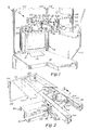
- Figure 1 is a perspective view of one embodiment of the suspension system of this invention incorporated into a modular partition unit
- a personal computer system may comprise any number of various components, including most notably the central processing unit (CPU) 11, keyboard, and a display device 12 such as a monitor.
- CPU central processing unit
- keyboard e.g., a keyboard
- display device 12 e.g., a monitor
- a monitor 12 may be seen supported by the suspension system 10 of this invention above a generally horizontal, planar work surface 14, which is bounded on two sides by a modular partition system 16.
- the suspension system 10 consists of a monitor carriage 18 comprised of a number of wire members 20 bent into rectangular hoops and attached to form a generally box-shaped cage. Each wire member 20, as well as other components of the monitor carriage 18, may be coated with a plastic resin or rubber compound to prevent scratching or abrasion of the monitor 12.
- the wire members 20 are fastened to a support plate 22 at the top 24 of the monitor carriage 18 using welding or other similar fastening means.
- the wire members 20 are attached along the bottom 26 of the monitor carriage 18 by a monitor platform (not shown) of any size or type known to the art and used for supporting a monitor 12 or other personal computer component.
- the monitor carriage 18 may be sized and proportioned to accommodate any standard sizes of monitors 12 or personal computers, as well as any custom size suited for particular applications or systems.
- the monitor carriage 18 may include a gripping handle 28 formed from one of the wire members 20 and positioned to depend from the monitor carriage 18 and extend outwardly in front of the monitor 12.
- Attached to the support plate 22 is a frictional swivel and tilt mechanism 30 of the type disclosed in the previously referenced United States Patent No. 4,453,687.
- the swivel and tilt mechanism 30 is attached to the support plate 22 in an inverted position using any suitable fastening means such as welding.
- any suitable fastening means such as welding.
- any of a variety of known mechanisms providing for rotation, tilting, swiveling, or other movement may be employed, it has proved particularly desirable to use the swivel and tilt mechanism 30 disclosed in the '687 patent, since conventional ball-and-socket mechanisms do not operate satisfactorily when inverted, and to obviate the need for complex locking or securing attachments.
- the spindle or post 32 of the swivel and tilt mechanism 30 is received within and securely fastened to a post collar 34 using a locking pin or similar suitable fastening means, the post collar 34 in turn being attached to an extension arm 36.
- the extension arm 36 includes a pair of spaced apart mounting plates 38 which receive and engagingly bracket a pair of parallel support arms 40. Each support arm 40 is pivotally fastened between the mounting plates 38 by a securing pin 42 which extends entirely through the surfaces thereof.
- the support arms 40 each comprise a section of straight channel having a U-shaped cross section, as shown in Figure 2. Referring to Figures 1 and 2, the opposing ends of the support arms 40 are similarly received between and bracketed by the opposing sides 44 of a pivot housing 46, the support arms 40 being pivotable fastened to the pivot housing by a pair of securing pins 42.
- the pivot housing 46 may be of any shape or dimensions which allow the parallel support arms 40 to pivot downward relative to the pivot housing 46, thereby requiring a portion of the bottom section 48 of the pivot housing 46 to be cut away or exposed.
- the pivot housing 46 similarly brackets and receives one end of a pneumatic pressure cylinder 50.
- the pneumatic pressure cylinder 50 may be any one of a type known to the art for assisting in the movement of or counterbalancing weighted objects. It has proven satisfactory to utilize a pneumatic cylinder 50 providing 160 pounds of pressure to accommodate monitors weighing between 20 and 50 pounds, while a pneumatic cylinder 50 of 215 pounds has proven satisfactory for monitors of 50-80 pounds.
- the pneumatic cylinder 50 is attached at the distal end 52 of the top support arm 40 using the securing pin 42 and a standard two-bladed coupling yoke 54 of the type commonly used with similar cylinders and shown in FIgure 2 and 4.
- the pneumatic cylinder 50 extends diagonally between the support arms 40 to the proximal end 56 of the lower support arm 40.
- the pneumatic cylinder 50 is fastened to an adjustment mechanism 58 which permits the counterbalancing pressure exerted by the pneumatic cylinder 50 to be adjusted to accommodate different weight monitors 12, and to compensate for the gradual decrease in pneumatic pressure encountered over the usual life of a pneumatic cylinder 50.
- the adjustment mechanism 58 consists of a block 60 defining a sliding channel 62 which extends through the total length of block 60.
- Block 60 in turn is mounted within the confines of the pivot housing 46 at an angle of 35° of vertical using the securing pin 42.
- Block 60 incorporates a recessed area or "nest” 59 wherein rotates a commonly available set screw 61 which incorporates an Allen hex drive wrench access groove 65.
- a movable adjustable slide 63 is connected to the pneumatic cylinder coupling yoke 54 by means of a pin 64 inserted therethrough. The movable adjustment slide 63 is inserted into the sliding channel 62 of block 60.
- the threaded channel 66 in movable adjustment slide 63 engages the set screw 61.
- movable adjustment slide 63 moves up and down along the fixed block 60 to provide a movable anchor point or carrier member for the pneumatic cylinder 50, thereby increasing or decreasing the overall height or length of pneumatic cylinder 50 and thus the pressure exerted by the pneumatic cylinder 50.
- the pivot housing 46 is mounted to a U-shaped truck member 94 which is positioned between a pair of parallel opposing track members. 96, each track member 96 having a generally C-shaped cross section.
- the pivot housing 46 is rotatable fastened to the truck member 94 by a centrally located bolt 98 which extends entirely through apertures in the top surface 100 of the pivot housing 46 and bottom surface 102 of the truck member 94, and is secured thereto by a pair of corresponding threaded fasteners 104.
- pivot housing 46 While the pivot housing 46 is supported by and suspended from the truck member 94 and is free to rotate relative to the truck member 94, the pivot housing 46 should be mounted to the truck member 94 such that the pivot housing 46 and the support arms 40 extending from the pivot housing 40 will not tilt downward or from side to side. To prevent such tilting, the facing surfaces 100, 102 of the pivot housing 46 and truck member 94 must be maintained generally parallel and proximate to one another in close confronting contact, and may be separated by a teflon pad or other suitable friction reducing element to ensure that the pivot housing 46 may be easily rotated.
- the pivot housing 46 and truck member 94 may additionally include any known type of collar or bearing assembly designed to maintain the pivot housing 46 in position beneath the truck member 94 and permit freedom of rotation.
- each axle 108 Extending through the upstanding side walls 106 of the truck member 94 are a pair of axles 108, each axle 108 having a roller wheel 110 rotatably attached to the opposing ends thereof, with opposing pairs of the roller wheels 110 being received within the interior region of the track members 96.
- Each roller wheel 110 may be securely mounted to the axle 108 using any conventionally known method, such as by inserting the end of the axle 108 within a centrally located aperture defined by each of the roller wheels 110, and fastening the roller wheels 110 to the ends of the axles 108 using a threaded fastener 112 having reverse threads.
- the truck member 94 may be carried back and forth along the track members 96 between various points.
- the track members 96 may each be substantially linear, as shown in Figure 2, or may conform to any predetermined pattern or path having curves and turns of sufficient radius to permit the truck member 94 to be carried on the roller wheels 110 over the entire length or the track members 96.
- the track members 96 are then attached to a support frame members 114 such as a shelving unit using welding or rivets 116 such that the track members 96 are suspended beneath the generally horizontal planar upper surface 118 of the shelving unit 114.
- the track members 96 may be attached at each end to mounting brackets 120 extending inwardly from side plates 122 to support the track members 96 below the upper surface 118 of the shelving unit 114, particularly if the upper surface 118 is to be removable for the shelving unit 114.
- the shelving unit 114 may be mounted to a modular partition system 16 using any conventional mounting system, such as tabs 124 which extend from the shelving unit 114 and are engagingly received within vertical brackets 126 having slots 128 corresponding to those tabs 124.
- the shelving unit 114 may be placed along a partition member 130 along with other accessory items such as shelves or bookcases 132.
- the front edge 134 of the shelving unit 114 is canted upwardly approximately 1/16 the of an inch relative to horizontal, as are the mounting plates 38 relative to the distal end 52 of the support arms 40.
- the shelving unit 114 may be attached to a modular partition system 16 at a height permitting the suspension system 10 to depend therefrom with the monitor carriage 18 suspended over the work surface 14.
- the monitor 12 is placed within the monitor carriage 18, and the adjustment screw 78 within the block 60 is adjusted to accommodate the particular weight of the monitor 12.
- the CPU or other items may be placed on the shelving unit 114, with the keyboard, mouse, or other items places on the work surface 14 and the components connected to the monitor 12 or CPU using cables.
- a user seated at the work surface 14 may then grasp the gripping handle 28 at the front of the monitor carriage 18, and position the monitor screen at any appropriate height, angle, degree of rotation, and pivot the monitor carriage 18 toward or away from the front edge of the work surface 14.
- the user may roll the truck member 94 along the track members 96 and thereby carry the entire suspension system 10 back and forth along the full extent of the track members 96.
- the track members 96 may be placed along a path between two distinct points such as separate work stations such that a single monitor 12 may be shared or used at both points, or that the track members 96 may be curved to cooperate with various office settings and work station configurations.
- the user when desiring to place monitor 12 away from the work surface 14, may lift the monitor carriage 18 to a position just below the shelving unit, rotate the monitor carriage 18 such that the front edge of the monitor 12 is generally parallel with the front edge 134 of the shelving unit 114, and pivot the support arms 40 and suspension system 10 to a position beneath the shelving unit 114 and displaced from the work surface.
- a saddle- shaped monitor carriage 136 shown in Figures 5 and 6, comprises a pair of curved tubular metal brace members 138, 140, with the upstanding leg portions 142 of the lower brace member 138 being received within the depending leg portions 144 of the upper brace member 140.
- the brace members 138, 140 may be fastened together as shown in Figure 6 using threaded or push-type fasteners 146 which extend entirely through aligned apertures 148 in the leg portions 142, 144 for the corresponding brace members 138, 140.
- the overall height of the monitor carriage 136 may be adjusted to fit a particular monitor 12 or personal computer, and to maximize the clearance between the work surface 14 and the monitor carriage 136.
- the saddle-shaped carriage 136 presents two pair of generally horizontal frame members 147, 149 spaced apart a variable distance by the vertical leg portions 142. 144.
- FIG. 7 Another embodiment of the suspension system 10 for use with desks and outer work surfaces 14 not bounded by partitions 16 is shown in Figure 7.
- the suspension system 10 is similarly supported beneath a shelving unit 150 which is attached to a pair of vertical frame members 152 and a support base member 154 or pedestal which may extend under at least a portion of the desk 156 and suspension arms 40 to provide the leverage necessary to support a personal computer or monitor 12 along with the suspension system 10 itself.
- the shelving unit 150 can be used to mount the personal computer within easy reach of the operator, as shown in phantom in Figure 1.
Landscapes
- Engineering & Computer Science (AREA)
- General Engineering & Computer Science (AREA)
- Mechanical Engineering (AREA)
- Devices For Indicating Variable Information By Combining Individual Elements (AREA)
- Financial Or Insurance-Related Operations Such As Payment And Settlement (AREA)
- Small-Scale Networks (AREA)
- Hardware Redundancy (AREA)
- Debugging And Monitoring (AREA)
Priority Applications (1)
| Application Number | Priority Date | Filing Date | Title |
|---|---|---|---|
| AT88309600T ATE99787T1 (de) | 1987-10-15 | 1988-10-13 | Aufhaengevorrichtung fuer personalcomputer und datensichtgeraete. |
Applications Claiming Priority (2)
| Application Number | Priority Date | Filing Date | Title |
|---|---|---|---|
| US109028 | 1987-10-15 | ||
| US07/109,028 US4836478A (en) | 1987-10-15 | 1987-10-15 | Suspension system for personal computers and monitors |
Publications (3)
| Publication Number | Publication Date |
|---|---|
| EP0312355A2 true EP0312355A2 (fr) | 1989-04-19 |
| EP0312355A3 EP0312355A3 (en) | 1989-08-16 |
| EP0312355B1 EP0312355B1 (fr) | 1994-01-05 |
Family
ID=22325440
Family Applications (1)
| Application Number | Title | Priority Date | Filing Date |
|---|---|---|---|
| EP88309600A Expired - Lifetime EP0312355B1 (fr) | 1987-10-15 | 1988-10-13 | Dispositif de suspension pour ordinateurs personnels et écrans de visualisation |
Country Status (6)
| Country | Link |
|---|---|
| US (1) | US4836478A (fr) |
| EP (1) | EP0312355B1 (fr) |
| JP (1) | JPH07109540B2 (fr) |
| AT (1) | ATE99787T1 (fr) |
| CA (1) | CA1328446C (fr) |
| DE (1) | DE3886884T2 (fr) |
Cited By (19)
| Publication number | Priority date | Publication date | Assignee | Title |
|---|---|---|---|---|
| DE4003992A1 (de) * | 1990-02-09 | 1991-08-14 | Horst Haseke | Geraetetragarm fuer steuertafeln, steuergehaeuse o. dgl. |
| DE4115659A1 (de) * | 1991-05-14 | 1992-11-19 | Peter Jordan | Aufhaengung fuer unterhaltungsgeraete und moebel |
| WO1994029636A1 (fr) * | 1993-06-04 | 1994-12-22 | Kreuzer Gmbh & Co. Ohg | Statif avec equilibrage des masses |
| DE29607728U1 (de) * | 1996-04-29 | 1996-07-25 | Bültmann, Monika, 58809 Neuenrade | Elektrisches Steuerpult |
| DE29513608U1 (de) * | 1995-08-24 | 1996-09-26 | Heilberufe Marketinggesellschaft mbH, 85410 Haag | Halterung für Flachbildschirme |
| EP0737834A3 (fr) * | 1995-04-03 | 1996-12-04 | Ergotron Inc | Poste de travail |
| GB2306838A (en) * | 1995-10-19 | 1997-05-07 | Daewoo Electronics Co Ltd | Means to tilt a display panel in both horizontal and vertical directions |
| GB2306837A (en) * | 1995-10-19 | 1997-05-07 | Daewoo Electronics Co Ltd | Means to tilt a display panel in both horizontal and vertical directions |
| EP0816744A1 (fr) * | 1996-06-28 | 1998-01-07 | Hill-Rom, Inc. | Bras à équilibrage constant pour écran |
| EP0942221A1 (fr) * | 1998-03-09 | 1999-09-15 | Krauss-Maffei Wegmann GmbH & Co. KG | Console déplacable de maintien d'un appareil, en particulier un écran de l'intérieur d'un véhicule, en particulier un véhicule de combat |
| GB2338182A (en) * | 1998-05-20 | 1999-12-15 | Alfred Charles Main | Sliding support stand, e.g. for monitor. |
| EP1158238A1 (fr) * | 2000-05-23 | 2001-11-28 | USM Holding AG | Support d'appareils |
| EP1249367A3 (fr) * | 2001-04-10 | 2004-10-20 | SEA Società Europea Autocaravan S.p.A. | Dispositif d'accueil et d'orientation d'une télévision dans un véhicule automobile |
| GB2414173A (en) * | 2004-05-19 | 2005-11-23 | Avf Group Ltd | Mounting Bracket |
| US7097145B2 (en) | 2001-09-14 | 2006-08-29 | Hill-Rom Services, Inc. | Support arm for a surgical theater system |
| EP1857726A3 (fr) * | 2006-05-20 | 2008-09-24 | Zhanxiang Technology (Huizhou) Co., Ltd. | Support d'un appareil de télévision à écran plat |
| NL1035891C (nl) * | 2008-09-03 | 2010-03-16 | Vogel S Holding Bv | Inrichting geschikt voor het ondersteunen van een component. |
| CN102425711A (zh) * | 2011-08-18 | 2012-04-25 | 苏州佳世达光电有限公司 | 屏幕支撑装置及具有该支撑装置的显示装置 |
| EP2367248A3 (fr) * | 2010-03-15 | 2014-06-25 | Waldner Labor- und Schuleinrichtungen GmbH | Dispositif d'alimentation en fluide pour la préparation et l'élimination de fluides |
Families Citing this family (147)
| Publication number | Priority date | Publication date | Assignee | Title |
|---|---|---|---|---|
| USRE34266E (en) * | 1984-02-16 | 1993-06-01 | Work station with underdesk display | |
| USD322857S (en) | 1988-11-14 | 1991-12-31 | Cell Analysis Systems, Inc. | Dual color camera with microscope and digital analyzer work station |
| JPH0351473U (fr) * | 1989-09-22 | 1991-05-20 | ||
| US5163649A (en) * | 1990-03-30 | 1992-11-17 | The United States Of America As Represented By The Secretary Of The Air Force | Multi-axis positional gimbal |
| US5135196A (en) * | 1990-03-30 | 1992-08-04 | The United States Of America As Represented By The Secretary Of The Air Force | Multi-axis positional gimbal |
| US5009384A (en) * | 1990-06-29 | 1991-04-23 | Inter-Link Communciations Inc. | Overhead support system for TV monitors |
| US5038169A (en) * | 1990-09-28 | 1991-08-06 | Xerox Corporation | Plural mode printer user interface terminal |
| US5408939A (en) * | 1990-10-11 | 1995-04-25 | Nova Manufacturing & Assembly, Inc. | Adjustable monitor support |
| US5125727A (en) * | 1990-10-11 | 1992-06-30 | Nova Office Furniture, Inc. | Adjustable monitor support assembly |
| US5699744A (en) * | 1990-10-11 | 1997-12-23 | Nova Solutions, Inc. | Adjustable monitor support for flat monitors |
| US5108063A (en) * | 1990-11-01 | 1992-04-28 | Hill-Rom Company, Inc. | Hospital room computer mounting arm |
| CA2074218C (fr) * | 1991-10-10 | 2000-07-18 | Timothy H. Schipper | Support reglable, a deux surfaces de travail |
| US5352033A (en) * | 1992-03-27 | 1994-10-04 | Fisher-Rosemount Systems, Inc. | Operator work station having a monitor support assembly |
| US5630648A (en) * | 1992-08-27 | 1997-05-20 | Harry C. Sweere | Dynamic posture chair |
| US5400993A (en) * | 1993-08-17 | 1995-03-28 | Hamilton; Clifton | Adjustable overhead suspension apparatus for TV and VCR |
| US5490655A (en) * | 1993-09-16 | 1996-02-13 | Monger Mounts, Inc. | Video/data projector and monitor ceiling/wall mount |
| US5405117A (en) * | 1993-10-27 | 1995-04-11 | Davis; Greig S. | Gliding ceiling monitor support assembly |
| USD360545S (en) | 1993-11-15 | 1995-07-25 | Nova Manufacturing & Assembly, Inc. | Work station |
| US5876008A (en) * | 1995-01-17 | 1999-03-02 | Ergotron, Inc. | Suspension system for video monitor or other equipment |
| USD367271S (en) | 1995-03-30 | 1996-02-20 | Texecom, Inc. | Monitor housing with mounting bracket |
| US5655822A (en) * | 1995-04-19 | 1997-08-12 | Roberts; Fay D. | Trapezoidal hidden-monitor computer desk modules and assemblies thereof |
| US5765797A (en) * | 1995-12-12 | 1998-06-16 | Greene; H. Peter | Articulated support for computers and the like |
| ES1034279U (es) * | 1996-05-30 | 1996-12-16 | Telefonica Nacional Espana Co | Soporte poliposicionable para monitores de television. |
| US5842672A (en) * | 1996-06-07 | 1998-12-01 | Ergotron, Inc. | Mounting system for flat panel display, keyboard and stand |
| US5988571A (en) * | 1997-09-22 | 1999-11-23 | Ward; Glenn F. | TV/VCR mount |
| US6012694A (en) * | 1998-01-27 | 2000-01-11 | Sullivan Construction Company | Monitor suspension system |
| US6012693A (en) * | 1998-02-19 | 2000-01-11 | Ergotron, Inc. | Multi-function display mounting system |
| US6095468A (en) * | 1998-03-27 | 2000-08-01 | Hill-Rom, Inc. | Support arm for a service column |
| US7612999B2 (en) * | 1998-09-18 | 2009-11-03 | Flo Healthcare Solutions, Llc | Mobile clinical workstation |
| US6883438B2 (en) | 1998-10-20 | 2005-04-26 | Garry William Allen | Mounting assembly |
| AUPR501701A0 (en) * | 2001-05-16 | 2001-06-07 | Intellec Pty Ltd | Mounting assembly |
| US6343006B1 (en) | 1998-11-20 | 2002-01-29 | Jerry Moscovitch | Computer display screen system and adjustable screen mount, and swinging screens therefor |
| DE19983832T1 (de) | 1998-12-23 | 2001-11-29 | Jerry Moscovitch | Computer-Anzeigebildschirmsystem und verstellbare Bildschirmhalterung sowie schwenkbare Bildschirme dafür |
| US6394402B2 (en) | 1999-09-01 | 2002-05-28 | Stinger Industries, Llc | Vertically adjustable mobile computer workstation |
| CN1249553C (zh) | 1999-11-12 | 2006-04-05 | 杰丽·莫斯可维奇 | 水平的三屏液晶显示系统 |
| USD462359S1 (en) | 2000-05-23 | 2002-09-03 | Usm Holding Ag | Screen holding device |
| DE20018361U1 (de) * | 2000-10-26 | 2001-04-05 | Hung, Ray, Wu-Chi, Taichung | Haltevorrichtung für ein Flüssig-Kristallbildschirm |
| US20060238529A1 (en) * | 2000-10-27 | 2006-10-26 | Lavelle Patrick M | Vehicle display device having a wireless transmitter |
| US7679578B2 (en) * | 2003-05-15 | 2010-03-16 | Audiovox Corporation | Headrest mountable video system |
| US20070091015A1 (en) * | 2000-10-27 | 2007-04-26 | Lavelle Patrick M | Vehicle seat entertainment system incorporating a databus |
| US7839355B2 (en) * | 2000-10-27 | 2010-11-23 | Audiovox Corporation | Vehicle display device having a wireless transmitter |
| US7667669B2 (en) * | 2000-10-27 | 2010-02-23 | Audiovox Corporation | Vehicle display device having a wireless transmitter |
| US7032870B2 (en) * | 2000-11-28 | 2006-04-25 | Ergotron, Inc. | Methods and apparatus for generating force and torque |
| US6994306B1 (en) * | 2000-11-28 | 2006-02-07 | Constant Force Technology, Llc | Monitor support system |
| WO2003000091A2 (fr) * | 2001-06-20 | 2003-01-03 | Innovative Office Products, Inc. | Bras d'ecran reglable pour composants d'ordinateur |
| EP2302541B1 (fr) * | 2001-08-03 | 2016-09-28 | Hill-Rom Services, Inc. | Système informatique de point d'intervention de patient |
| JP3687589B2 (ja) * | 2001-11-12 | 2005-08-24 | 日本電気株式会社 | 表示装置用固定具 |
| US7138997B2 (en) * | 2002-06-28 | 2006-11-21 | Autodesk, Inc. | System for physical rotation of volumetric display enclosures to facilitate viewing |
| US7109959B2 (en) | 2002-02-06 | 2006-09-19 | Andersen Corporation | Multi-task window |
| US7180489B2 (en) * | 2002-02-06 | 2007-02-20 | Andersen Corporation | Automated multi-task window assembly |
| US6684929B2 (en) | 2002-02-15 | 2004-02-03 | Steelcase Development Corporation | Panel system |
| US6851226B2 (en) * | 2002-02-15 | 2005-02-08 | Steelcase Development Corporation | Partition panel with modular appliance mounting arrangement |
| US6905101B1 (en) * | 2002-06-11 | 2005-06-14 | Chief Manufacturing Inc. | Adjustable, self-balancing flat panel display mounting system |
| US6997422B2 (en) * | 2002-08-21 | 2006-02-14 | Ergotron, Inc. | Stand |
| US6915995B2 (en) | 2002-10-30 | 2005-07-12 | Peerless Industries, Inc. | Underbody mounting system |
| BR8202789U (pt) * | 2002-12-03 | 2004-07-20 | Brasforma Ind E Com Ltda | Disposição construtiva introduzida em suporte de parede para televisor e outros aparelhos |
| US7152836B2 (en) * | 2003-01-09 | 2006-12-26 | Csav, Inc. | Adjustable tilt mount |
| US7252277B2 (en) | 2003-01-17 | 2007-08-07 | Ergotron, Inc. | Support arm |
| US7410138B2 (en) * | 2003-03-14 | 2008-08-12 | Tgr Intellectual Properties, Llc | Display adjustably positionable about swivel and pivot axes |
| US7065811B2 (en) * | 2003-03-18 | 2006-06-27 | Hill-Rom Services, Inc. | Radial arm system for patient care equipment |
| US7609946B2 (en) | 2003-05-15 | 2009-10-27 | Audiovox Corporation | Portable video system |
| US7909397B2 (en) * | 2003-05-15 | 2011-03-22 | Audiovox Corporation | In-vehicle docking station for a portable media player |
| US7791586B2 (en) | 2003-05-15 | 2010-09-07 | Audiovox Corporation | Entertainment system mountable in a vehicle seat |
| US7780231B2 (en) * | 2003-05-15 | 2010-08-24 | Audiovox Corporation | Entertainment system mountable in a vehicle seat and methods for mounting and displaying same |
| US7954894B2 (en) * | 2003-05-15 | 2011-06-07 | Audiovox Corporation | Headrest mountable video system |
| US20040250635A1 (en) * | 2003-05-20 | 2004-12-16 | Sweere Harry C. | Lift mechanism based on torque equalization principles |
| US8925154B2 (en) | 2003-05-20 | 2015-01-06 | Ergotron, Inc. | Pivot mechanism for adjusting a position of an electronic display |
| US20060185563A1 (en) * | 2004-07-30 | 2006-08-24 | Sweere Harry C | Lift mechanism systems and methods |
| US7380760B2 (en) * | 2003-05-30 | 2008-06-03 | Csav, Inc. | Self-balancing adjustable mounting system with friction adjustment |
| US7028961B1 (en) * | 2003-05-30 | 2006-04-18 | Csav, Inc. | Self-balancing adjustable flat panel mounting system |
| US7472458B2 (en) * | 2003-06-13 | 2009-01-06 | Innovative Office Products, Inc. | Tilter apparatus for electronic device having bias assembly |
| US7063296B2 (en) * | 2003-06-13 | 2006-06-20 | Innovative Office Products, Inc. | Rail mounting apparatus for electronic device |
| EP1660804A2 (fr) * | 2003-08-01 | 2006-05-31 | Constant Force Technology, LLC | Mecanismes bases sur des principes d'egalisation de couple |
| US20050111176A1 (en) * | 2003-10-03 | 2005-05-26 | Sorensen Shane D. | Sidewall display system |
| US7849978B2 (en) * | 2003-10-13 | 2010-12-14 | Hill-Rom Services, Inc. | Brake system for patient care equipment support arm |
| US20050258321A1 (en) * | 2004-05-19 | 2005-11-24 | Raymond Worrall | Mounting bracket |
| US7677182B2 (en) | 2004-05-27 | 2010-03-16 | Steelcase Development Corporation | Two person work environment |
| US7460187B2 (en) * | 2004-08-25 | 2008-12-02 | Audiovox Corporation | Rail system for use in a vehicle |
| US8051610B2 (en) | 2004-09-22 | 2011-11-08 | Hill-Rom Services, Inc. | Patient flatwall system |
| US7604210B2 (en) * | 2004-09-23 | 2009-10-20 | Innovative Office Products, Inc. | Tilter apparatus having bias assembly |
| US8407944B2 (en) * | 2004-12-06 | 2013-04-02 | Steelcase Inc. | Multi-use conferencing space, table arrangement and display configuration |
| US20120287226A1 (en) | 2004-12-06 | 2012-11-15 | Baloga Mark A | Multi-Use Conferencing Space, Table Arrangement and Display Configuration |
| US7770247B2 (en) * | 2005-05-02 | 2010-08-10 | Hill-Rom Services, Inc. | Brake system for wall arm |
| WO2006132938A2 (fr) | 2005-06-03 | 2006-12-14 | Steel Case Development Corporation | Assemblage de bras de support |
| US7377475B1 (en) * | 2005-07-22 | 2008-05-27 | Rodovaldo Lopez | Television mount assembly |
| US20070023375A1 (en) * | 2005-07-26 | 2007-02-01 | Dale Fedewa | Display mount apparatus and system |
| US8713613B2 (en) | 2006-01-04 | 2014-04-29 | Voxx International Corporation | Data distribution unit for vehicle entertainment system |
| US20070153459A1 (en) * | 2006-01-04 | 2007-07-05 | Jim Wohlford | Mounting system for flat panel electronic display |
| US20100017827A1 (en) * | 2006-01-04 | 2010-01-21 | Audiovox Corporation | Receiver and distribution unit for vehicle entertainment system |
| US8180485B2 (en) | 2006-02-11 | 2012-05-15 | Omnicell, Inc. | Medication dispensing cart |
| WO2007120519A2 (fr) * | 2006-04-03 | 2007-10-25 | Metro Industries Inc. | Station de travail modulaire |
| US7997211B2 (en) * | 2006-06-12 | 2011-08-16 | Steelcase Inc. | Wall mounted workstation |
| US8228668B2 (en) | 2006-07-26 | 2012-07-24 | Ergotron, Inc. | Balanced moment lift system and method |
| ES2599211T3 (es) * | 2006-08-21 | 2017-01-31 | Omnicell, Inc. | Estaciones de trabajo móviles cargadas con energía solar |
| CA2674471C (fr) | 2007-01-03 | 2014-07-29 | Milestone Av Technologies, Inc. | Monture de dispositif ayant un axe de basculement pouvant etre selectivement positionne |
| US7866622B2 (en) * | 2007-01-05 | 2011-01-11 | Milestone Av Technologies Llc | In-wall mount |
| CA2649190C (fr) * | 2007-01-05 | 2014-10-07 | Csav, Inc. | Montage autoequilibrant et evitant le contact avec une paroi pour positionner de maniere basculante un ecran plat electronique |
| US7593219B2 (en) * | 2007-04-26 | 2009-09-22 | Hewlett-Packard Development Company, L.P. | Display support system and method |
| US8104850B2 (en) | 2007-05-30 | 2012-01-31 | Steelcase Inc. | Furniture storage unit |
| US8074581B2 (en) | 2007-10-12 | 2011-12-13 | Steelcase Inc. | Conference table assembly |
| DE102007057383A1 (de) * | 2007-11-27 | 2009-06-04 | Rittal Gmbh & Co. Kg | Befestigungsanordnung |
| US8251322B2 (en) | 2008-07-14 | 2012-08-28 | United Parcel Service Of America, Inc. | Cathode ray tube monitor to flat panel monitor conversion bracket |
| EP2329645A4 (fr) | 2008-09-02 | 2011-11-30 | Milestone Av Technologies Llc | Support extraplat pour dispositif d'affichage électronique à panneau plat |
| US20100059640A1 (en) * | 2008-09-10 | 2010-03-11 | Dental Equipment, Llc Dba Pelton & Crane | Electronic display mounting devices, cabinets including same, and methods of mounting electronic displays |
| US20140361954A1 (en) | 2013-06-07 | 2014-12-11 | Lewis Epstein | Personal control apparatus and method for sharing information in a collaboration workspace |
| US10631632B2 (en) | 2008-10-13 | 2020-04-28 | Steelcase Inc. | Egalitarian control apparatus and method for sharing information in a collaborative workspace |
| US8839630B2 (en) * | 2008-10-17 | 2014-09-23 | Hoffman Enclosures, Inc. | Thermoelectric dehumidifier and enclosure vent drain assembly |
| US8070120B2 (en) * | 2008-11-19 | 2011-12-06 | Hoffman Enclosures, Inc. | Vertical motion pendant arm |
| US8905496B2 (en) | 2008-12-11 | 2014-12-09 | Rubbermaid Incorporated | Wall work station |
| NL2002498C2 (nl) * | 2008-12-23 | 2010-06-24 | Teach You Bv | Ophangsysteem voor een elektronisch lesbord. |
| USD620943S1 (en) | 2009-01-07 | 2010-08-03 | Milestone Av Technologies Llc | Single arm display mount |
| USD627787S1 (en) | 2009-01-07 | 2010-11-23 | Milestone Av Technologies Llc | Display mount with single articulating arm |
| CA2749096C (fr) | 2009-01-07 | 2017-10-10 | Milestone Av Technologies Llc | Socle d'afficheur avec axe d'inclinaison a position reglable |
| US10884607B1 (en) | 2009-05-29 | 2021-01-05 | Steelcase Inc. | Personal control apparatus and method for sharing information in a collaborative workspace |
| US8174823B2 (en) * | 2009-06-15 | 2012-05-08 | Twelve South LLC | Computer monitor with a shelf |
| US8523131B2 (en) * | 2009-10-08 | 2013-09-03 | Innovative Office Products, Inc. | Tilter for positioning an electronic device |
| US20110108688A1 (en) * | 2009-11-09 | 2011-05-12 | Gazak Ventures Inc. | Set-top box support kit for LCD wall mounts |
| US8616136B2 (en) * | 2010-01-29 | 2013-12-31 | Rubbermaid Incorporated | Keyboard tray tilt |
| US8567735B2 (en) * | 2010-01-29 | 2013-10-29 | Rubbermaid Incorporated | Work station with height adjustment lock |
| US20110235249A1 (en) * | 2010-01-29 | 2011-09-29 | Rubbermaid Incorporated | Work surface articulation |
| US8618918B2 (en) | 2010-04-09 | 2013-12-31 | Hill-Rom Services, Inc. | Patient support, communication, and computing apparatus including movement of the support and connection to the hospital network |
| BR112013014098B1 (pt) | 2010-12-06 | 2020-10-27 | Omnicell, Inc | sistema e método para monitorar e controlar uma unidade de armazenamento médico |
| US8677911B2 (en) | 2011-02-18 | 2014-03-25 | Rubbermaid Incorporated | Technology cart |
| US8662605B2 (en) | 2011-02-18 | 2014-03-04 | Rubbermaid Incorporated | Mobile technology cabinet |
| US9508160B2 (en) | 2011-02-22 | 2016-11-29 | Xerox Corporation | User interface panel |
| US20130345604A1 (en) * | 2011-02-28 | 2013-12-26 | Murata Machinery, Ltd. | Upper Limb Training Apparatus |
| US9554966B2 (en) * | 2011-02-28 | 2017-01-31 | Murata Machinery, Ltd. | Upper limb training apparatus |
| US9228696B2 (en) | 2011-03-18 | 2016-01-05 | GCX Corporation | Variable height arm structures, systems, and methods |
| WO2013148352A1 (fr) | 2012-03-30 | 2013-10-03 | Ergotron, Inc. | Mécanismes de levage à contrepoids et procédés |
| US9539155B2 (en) | 2012-10-26 | 2017-01-10 | Hill-Rom Services, Inc. | Control system for patient support apparatus |
| US9933106B2 (en) | 2013-03-14 | 2018-04-03 | Capsa Solutions, Llc | Height adjustable support |
| US10474808B2 (en) | 2013-03-29 | 2019-11-12 | Hill-Rom Services, Inc. | Hospital bed compatibility with third party application software |
| JP5686846B2 (ja) * | 2013-05-27 | 2015-03-18 | シャープ株式会社 | 表示装置の保持機構 |
| NL2011445C2 (nl) | 2013-09-16 | 2015-03-18 | Vanderlande Ind Bv | Inrichting voor het manipuleren van bagagestukken. |
| CN104376795B (zh) * | 2014-11-14 | 2017-04-12 | 无锡悟莘科技有限公司 | 一种可升降led显示屏 |
| US10143298B2 (en) | 2016-04-07 | 2018-12-04 | Douglas Wood | Modular structural support apparatus and method of constructing the same |
| CN105967045A (zh) * | 2016-07-29 | 2016-09-28 | 孝感市卡普隆日用品有限公司 | 一种连接牢固的显示器吊装装置 |
| US10264213B1 (en) | 2016-12-15 | 2019-04-16 | Steelcase Inc. | Content amplification system and method |
| US10870397B2 (en) * | 2018-12-21 | 2020-12-22 | Nissan North America, Inc. | Accessory mounting system for vehicles |
| GB2580417B (en) | 2019-01-11 | 2025-01-29 | Arrow Group Global Ltd | Display device support arm |
| CA3128150A1 (fr) * | 2019-01-31 | 2020-08-06 | American Sterilizer Company | Bras de support pour systeme de support de dispositif medical |
| CN110566776B (zh) * | 2019-08-19 | 2024-10-11 | 天津大行道动漫文化发展有限公司 | 一种带有轴动翻转的斜面支撑可折叠收纳数位画板 |
| EP4071406A1 (fr) | 2021-04-09 | 2022-10-12 | TRUMPF Medizin Systeme GmbH + Co. KG | Étrier pour un système de suspension d'une lampe médicale, système de suspension et système comprenant un corps de lampe médicale et un système de suspension |
| EP4419040B1 (fr) | 2021-10-18 | 2025-06-18 | American Sterilizer Company | Bras d'équilibrage de charge pour système de support de dispositif médical |
| GB2622845B (en) | 2022-09-29 | 2025-01-01 | Arrow Group Global Ltd | Display device support arm having improved stability, adjustment mobility and modularity |
| US12516769B1 (en) * | 2023-04-20 | 2026-01-06 | Clifford B. Breed | Mobile overhead monitor bracket stand |
| DE102024105495A1 (de) | 2024-02-27 | 2025-08-28 | Krones Aktiengesellschaft | Schutzeinrichtung für eine Maschine |
Family Cites Families (24)
| Publication number | Priority date | Publication date | Assignee | Title |
|---|---|---|---|---|
| US507364A (en) * | 1893-10-24 | Hanger for electric lamps | ||
| US1733107A (en) * | 1927-09-20 | 1929-10-29 | Ahlberg Alfred | Reading appliance |
| US2941776A (en) * | 1957-05-13 | 1960-06-21 | Ritter Co Inc | Counterbalancing mechanism |
| US3358957A (en) * | 1965-05-26 | 1967-12-19 | Wells Television Inc | Bedstead television support |
| US3345461A (en) * | 1965-10-19 | 1967-10-03 | Earl L Bunting | Adjustable support means for a television receiver |
| US3417953A (en) * | 1966-10-31 | 1968-12-24 | Instrumentation Labor Inc | Mechanical support assemblies |
| US3433444A (en) * | 1967-01-04 | 1969-03-18 | Thomas F Smith | Counterpoised supporting device |
| FR1510371A (fr) * | 1967-02-03 | 1968-01-19 | Support pour récepteur de télévision | |
| GB1240837A (en) * | 1968-05-16 | 1971-07-28 | Rank Organisation Ltd | Improvements relating to camera systems |
| US3662981A (en) * | 1969-10-24 | 1972-05-16 | Dazor Mfg Corp | Articulated carrying frame |
| DE2528955A1 (de) * | 1975-06-28 | 1977-01-13 | Freimuth Wolfgang Dipl Wirtsch | Verstellbare vorrichtung zur decken-, wand- und bodenbefestigung von geraeten |
| US4158488A (en) * | 1976-07-19 | 1979-06-19 | Panavision, Incorporated | Body-mounted support device for motion picture camera |
| US4082244A (en) * | 1976-11-01 | 1978-04-04 | Groff Leroy K | Counterbalancing supporting device |
| US4166602A (en) * | 1978-05-18 | 1979-09-04 | Pennwalt Corporation | Counterbalancing mechanism for X-ray tubeheads |
| US4310136A (en) * | 1979-11-13 | 1982-01-12 | Quick-Set, Incorporated | Backlash-free swivel and tilt mounting |
| US4447031A (en) * | 1981-04-13 | 1984-05-08 | Positioning Devices, Inc. | Spring counterbalanced support arm system |
| US4453687A (en) * | 1982-03-01 | 1984-06-12 | Sweere Harry C | Swivel/tilt mounting device for a cathode ray tube |
| DE3416823A1 (de) * | 1983-06-06 | 1984-12-06 | Friedhelm 8000 München Kreuzer | Stativ mit einem zur hoehenverstellung schenkbaren ausleger |
| DE3321298A1 (de) * | 1983-06-13 | 1984-12-13 | Wilhelm Dr.-Ing. 5340 Bad Honnef Lepper | Kippvorrichtung fuer ein fernsehgeraet |
| FR2554269B1 (fr) * | 1983-10-26 | 1987-07-10 | Saunier Duval | Pupitre de commande et de controle a geometrie variable |
| US4562987A (en) * | 1984-05-14 | 1986-01-07 | Global Equipment Company | Computer terminal support with five degrees of freedom |
| DE3600613A1 (de) * | 1986-01-11 | 1987-07-16 | Wella Ag | Einrichtung zum positionieren von informationsgeraeten |
| US4706919A (en) * | 1986-12-17 | 1987-11-17 | Haworth, Inc. | Keyboard support with automatic lowering mechanism |
| US4852500A (en) * | 1987-03-18 | 1989-08-01 | Herman Miller, Inc. | Integrated computer implement work area |
-
1987
- 1987-10-15 US US07/109,028 patent/US4836478A/en not_active Expired - Lifetime
-
1988
- 1988-10-13 EP EP88309600A patent/EP0312355B1/fr not_active Expired - Lifetime
- 1988-10-13 DE DE88309600T patent/DE3886884T2/de not_active Expired - Fee Related
- 1988-10-13 AT AT88309600T patent/ATE99787T1/de active
- 1988-10-14 CA CA000580227A patent/CA1328446C/fr not_active Expired - Fee Related
- 1988-10-14 JP JP63257455A patent/JPH07109540B2/ja not_active Expired - Fee Related
Cited By (26)
| Publication number | Priority date | Publication date | Assignee | Title |
|---|---|---|---|---|
| DE4003992A1 (de) * | 1990-02-09 | 1991-08-14 | Horst Haseke | Geraetetragarm fuer steuertafeln, steuergehaeuse o. dgl. |
| DE4003992C2 (de) * | 1990-02-09 | 2001-08-16 | Haseke Gmbh & Co Kg | Gerätetragarm für Steuertafeln, Steuergehäuse o. dgl. |
| DE4115659A1 (de) * | 1991-05-14 | 1992-11-19 | Peter Jordan | Aufhaengung fuer unterhaltungsgeraete und moebel |
| WO1994029636A1 (fr) * | 1993-06-04 | 1994-12-22 | Kreuzer Gmbh & Co. Ohg | Statif avec equilibrage des masses |
| EP0737834A3 (fr) * | 1995-04-03 | 1996-12-04 | Ergotron Inc | Poste de travail |
| DE29513608U1 (de) * | 1995-08-24 | 1996-09-26 | Heilberufe Marketinggesellschaft mbH, 85410 Haag | Halterung für Flachbildschirme |
| US5715137A (en) * | 1995-10-19 | 1998-02-03 | Daewoo Electronics Co., Ltd. | Apparatus for providing tilting and rotational movements with pinion gears and rack |
| GB2306837A (en) * | 1995-10-19 | 1997-05-07 | Daewoo Electronics Co Ltd | Means to tilt a display panel in both horizontal and vertical directions |
| GB2306837B (en) * | 1995-10-19 | 2000-06-07 | Daewoo Electronics Co Ltd | Apparatus for providing tilting movement |
| US5715138A (en) * | 1995-10-19 | 1998-02-03 | Daewoo Electronics Co., Ltd. | Apparatus for providing a display with tilting and rotating movements with rack, pinion, and bevel gears |
| GB2306838A (en) * | 1995-10-19 | 1997-05-07 | Daewoo Electronics Co Ltd | Means to tilt a display panel in both horizontal and vertical directions |
| GB2306838B (en) * | 1995-10-19 | 2000-05-17 | Daewoo Electronics Co Ltd | Apparatus for providing tilting and rotational movements |
| DE29607728U1 (de) * | 1996-04-29 | 1996-07-25 | Bültmann, Monika, 58809 Neuenrade | Elektrisches Steuerpult |
| EP0816744A1 (fr) * | 1996-06-28 | 1998-01-07 | Hill-Rom, Inc. | Bras à équilibrage constant pour écran |
| US5826846A (en) * | 1996-06-28 | 1998-10-27 | Hill-Rom, Inc. | Monitor arm with constant counterbalance |
| EP0942221A1 (fr) * | 1998-03-09 | 1999-09-15 | Krauss-Maffei Wegmann GmbH & Co. KG | Console déplacable de maintien d'un appareil, en particulier un écran de l'intérieur d'un véhicule, en particulier un véhicule de combat |
| GB2338182A (en) * | 1998-05-20 | 1999-12-15 | Alfred Charles Main | Sliding support stand, e.g. for monitor. |
| EP1158238A1 (fr) * | 2000-05-23 | 2001-11-28 | USM Holding AG | Support d'appareils |
| WO2001090630A1 (fr) * | 2000-05-23 | 2001-11-29 | Usm Holding Ag | Dispositif de fixation d'appareil |
| EP1249367A3 (fr) * | 2001-04-10 | 2004-10-20 | SEA Società Europea Autocaravan S.p.A. | Dispositif d'accueil et d'orientation d'une télévision dans un véhicule automobile |
| US7097145B2 (en) | 2001-09-14 | 2006-08-29 | Hill-Rom Services, Inc. | Support arm for a surgical theater system |
| GB2414173A (en) * | 2004-05-19 | 2005-11-23 | Avf Group Ltd | Mounting Bracket |
| EP1857726A3 (fr) * | 2006-05-20 | 2008-09-24 | Zhanxiang Technology (Huizhou) Co., Ltd. | Support d'un appareil de télévision à écran plat |
| NL1035891C (nl) * | 2008-09-03 | 2010-03-16 | Vogel S Holding Bv | Inrichting geschikt voor het ondersteunen van een component. |
| EP2367248A3 (fr) * | 2010-03-15 | 2014-06-25 | Waldner Labor- und Schuleinrichtungen GmbH | Dispositif d'alimentation en fluide pour la préparation et l'élimination de fluides |
| CN102425711A (zh) * | 2011-08-18 | 2012-04-25 | 苏州佳世达光电有限公司 | 屏幕支撑装置及具有该支撑装置的显示装置 |
Also Published As
| Publication number | Publication date |
|---|---|
| ATE99787T1 (de) | 1994-01-15 |
| EP0312355A3 (en) | 1989-08-16 |
| DE3886884D1 (de) | 1994-02-17 |
| JPH07109540B2 (ja) | 1995-11-22 |
| CA1328446C (fr) | 1994-04-12 |
| US4836478A (en) | 1989-06-06 |
| EP0312355B1 (fr) | 1994-01-05 |
| JPH01200282A (ja) | 1989-08-11 |
| DE3886884T2 (de) | 1994-05-05 |
Similar Documents
| Publication | Publication Date | Title |
|---|---|---|
| EP0312355B1 (fr) | Dispositif de suspension pour ordinateurs personnels et écrans de visualisation | |
| US4562987A (en) | Computer terminal support with five degrees of freedom | |
| US6374752B1 (en) | Ergonomic computer workstation | |
| US10327544B2 (en) | Adjustable ergonomic workstation | |
| US6796536B1 (en) | Computer support apparatus and method | |
| US5073050A (en) | Ergonomic keyboard apparatus | |
| US5450800A (en) | Ergonomically adjustable computer workstation | |
| US4768744A (en) | Apparatus for supporting a load in a dynamically balanced condition | |
| US6298794B1 (en) | Ergonomic computer workstation | |
| US5806943A (en) | Mobile workstation | |
| US7134719B2 (en) | Peripheral support apparatus and method | |
| US5584546A (en) | Transportable office work station | |
| US4688862A (en) | Workstation for electronic equipment operator | |
| US5636822A (en) | Computer mouse support | |
| US5845586A (en) | Ergonomic workstation | |
| US5461974A (en) | Workstation with integrated computer | |
| US20120031310A1 (en) | Ergonomically designed large display multipurpose workstation | |
| US20030140822A1 (en) | Work table | |
| US5377598A (en) | Desktop mounted shelf with pivoting arms | |
| US8955905B2 (en) | Seating assembly having a seat-mounted attachment assembly for adjustable extension arm | |
| US6170406B1 (en) | Recessed monitor table | |
| US20040149178A1 (en) | Versatile workstation system | |
| US6604786B1 (en) | Support apparatus for a chair | |
| US6220181B1 (en) | Ergonomic CAD (computer aided design) workstation | |
| US20050211863A1 (en) | Computer workstation |
Legal Events
| Date | Code | Title | Description |
|---|---|---|---|
| PUAI | Public reference made under article 153(3) epc to a published international application that has entered the european phase |
Free format text: ORIGINAL CODE: 0009012 |
|
| AK | Designated contracting states |
Kind code of ref document: A2 Designated state(s): AT CH DE FR GB IT LI NL SE |
|
| PUAL | Search report despatched |
Free format text: ORIGINAL CODE: 0009013 |
|
| AK | Designated contracting states |
Kind code of ref document: A3 Designated state(s): AT CH DE FR GB IT LI NL SE |
|
| 17P | Request for examination filed |
Effective date: 19900202 |
|
| 17Q | First examination report despatched |
Effective date: 19910506 |
|
| GRAA | (expected) grant |
Free format text: ORIGINAL CODE: 0009210 |
|
| AK | Designated contracting states |
Kind code of ref document: B1 Designated state(s): AT CH DE FR GB IT LI NL SE |
|
| PG25 | Lapsed in a contracting state [announced via postgrant information from national office to epo] |
Ref country code: SE Effective date: 19940105 |
|
| REF | Corresponds to: |
Ref document number: 99787 Country of ref document: AT Date of ref document: 19940115 Kind code of ref document: T |
|
| ITF | It: translation for a ep patent filed | ||
| REF | Corresponds to: |
Ref document number: 3886884 Country of ref document: DE Date of ref document: 19940217 |
|
| ET | Fr: translation filed | ||
| PLBE | No opposition filed within time limit |
Free format text: ORIGINAL CODE: 0009261 |
|
| STAA | Information on the status of an ep patent application or granted ep patent |
Free format text: STATUS: NO OPPOSITION FILED WITHIN TIME LIMIT |
|
| 26N | No opposition filed | ||
| REG | Reference to a national code |
Ref country code: FR Ref legal event code: TP Ref country code: FR Ref legal event code: CA |
|
| REG | Reference to a national code |
Ref country code: CH Ref legal event code: PUE Owner name: ERGOTRON, INC. TRANSFER- HARRY C. SWEERE |
|
| REG | Reference to a national code |
Ref country code: GB Ref legal event code: 732E |
|
| NLS | Nl: assignments of ep-patents |
Owner name: H.C. SWEERE |
|
| PGFP | Annual fee paid to national office [announced via postgrant information from national office to epo] |
Ref country code: FR Payment date: 20000919 Year of fee payment: 13 |
|
| PGFP | Annual fee paid to national office [announced via postgrant information from national office to epo] |
Ref country code: DE Payment date: 20000920 Year of fee payment: 13 |
|
| PGFP | Annual fee paid to national office [announced via postgrant information from national office to epo] |
Ref country code: GB Payment date: 20000921 Year of fee payment: 13 Ref country code: AT Payment date: 20000921 Year of fee payment: 13 |
|
| PGFP | Annual fee paid to national office [announced via postgrant information from national office to epo] |
Ref country code: NL Payment date: 20000925 Year of fee payment: 13 |
|
| PGFP | Annual fee paid to national office [announced via postgrant information from national office to epo] |
Ref country code: CH Payment date: 20000928 Year of fee payment: 13 |
|
| PG25 | Lapsed in a contracting state [announced via postgrant information from national office to epo] |
Ref country code: GB Free format text: LAPSE BECAUSE OF NON-PAYMENT OF DUE FEES Effective date: 20011013 Ref country code: AT Free format text: LAPSE BECAUSE OF NON-PAYMENT OF DUE FEES Effective date: 20011013 |
|
| PG25 | Lapsed in a contracting state [announced via postgrant information from national office to epo] |
Ref country code: LI Free format text: LAPSE BECAUSE OF NON-PAYMENT OF DUE FEES Effective date: 20011031 Ref country code: CH Free format text: LAPSE BECAUSE OF NON-PAYMENT OF DUE FEES Effective date: 20011031 |
|
| REG | Reference to a national code |
Ref country code: GB Ref legal event code: IF02 |
|
| PG25 | Lapsed in a contracting state [announced via postgrant information from national office to epo] |
Ref country code: NL Free format text: LAPSE BECAUSE OF NON-PAYMENT OF DUE FEES Effective date: 20020501 |
|
| GBPC | Gb: european patent ceased through non-payment of renewal fee |
Effective date: 20011013 |
|
| REG | Reference to a national code |
Ref country code: CH Ref legal event code: PL |
|
| PG25 | Lapsed in a contracting state [announced via postgrant information from national office to epo] |
Ref country code: FR Free format text: LAPSE BECAUSE OF NON-PAYMENT OF DUE FEES Effective date: 20020628 |
|
| NLV4 | Nl: lapsed or anulled due to non-payment of the annual fee |
Effective date: 20020501 |
|
| PG25 | Lapsed in a contracting state [announced via postgrant information from national office to epo] |
Ref country code: DE Free format text: LAPSE BECAUSE OF NON-PAYMENT OF DUE FEES Effective date: 20020702 |
|
| REG | Reference to a national code |
Ref country code: FR Ref legal event code: ST |
|
| PG25 | Lapsed in a contracting state [announced via postgrant information from national office to epo] |
Ref country code: IT Free format text: LAPSE BECAUSE OF NON-PAYMENT OF DUE FEES;WARNING: LAPSES OF ITALIAN PATENTS WITH EFFECTIVE DATE BEFORE 2007 MAY HAVE OCCURRED AT ANY TIME BEFORE 2007. THE CORRECT EFFECTIVE DATE MAY BE DIFFERENT FROM THE ONE RECORDED. Effective date: 20051013 |