EP0312381A2 - Fermeture pour portes, fenêtres ou similaires - Google Patents
Fermeture pour portes, fenêtres ou similaires Download PDFInfo
- Publication number
- EP0312381A2 EP0312381A2 EP88309640A EP88309640A EP0312381A2 EP 0312381 A2 EP0312381 A2 EP 0312381A2 EP 88309640 A EP88309640 A EP 88309640A EP 88309640 A EP88309640 A EP 88309640A EP 0312381 A2 EP0312381 A2 EP 0312381A2
- Authority
- EP
- European Patent Office
- Prior art keywords
- handle
- base
- movement
- fixture
- closure member
- Prior art date
- Legal status (The legal status is an assumption and is not a legal conclusion. Google has not performed a legal analysis and makes no representation as to the accuracy of the status listed.)
- Withdrawn
Links
Images


Classifications
-
- E—FIXED CONSTRUCTIONS
- E05—LOCKS; KEYS; WINDOW OR DOOR FITTINGS; SAFES
- E05B—LOCKS; ACCESSORIES THEREFOR; HANDCUFFS
- E05B13/00—Devices preventing the key or the handle or both from being used
- E05B13/10—Devices preventing the key or the handle or both from being used formed by a lock arranged in the handle
- E05B13/106—Devices preventing the key or the handle or both from being used formed by a lock arranged in the handle for handles pivoted about an axis perpendicular to the wing
Definitions
- This invention relates to apparatus for fastening of a closure member in a fixture opening and is particularly concerned with casement fasteners for locking a window in a window frame.
- handle apparatus for fastening of a closure member in a fixture opening
- the apparatus comprising a base for mounting on one of the fixture and the closure member, a handle pivotally mounted on the base for movement between a closed position preventing movement, and an open position enabling movement of the closure member relative to the fixture, and means for locking the handle in the closed position
- the locking means comprising a formation of the handle and a projection on the base, the formation partly surrounding the projection in the closed position of the handle and, in that position of the handle, being rotatable in the handle between a locking position, wherein movement of the handle to the open position is prevented by engagement between the projection and the formation, and a release position wherein there is no such engagement.
- the formation is of part circular form and is provided on a main body of the locking means, the projection being in the form of a pin.
- the locking means may have means for biassing the formation into a position co-axial with the pin, the biassing means being integrally formed with the main body.
- the main body with the biassing means may be formed of a plastics material, and the biassing means may comprise a spring loaded finger on the main body resiliently projecting therefrom whereby to engage in a recess in the handle.
- the recess may have an arcuate form, engagement of the finger with respective ends of the recess determining the extent of rotation of the main body in a respective direction.
- the main body preferably has an extension part presenting a slotted end accessible from externally of the handle for operative engagement by a key.
- the invention also provides handle apparatus for fastening of a closure member in a fixture opening, the apparatus comprising a base for mounting on one of the fixture and the closure member, a handle pivotally mounted on the base for movement between a closed position preventing movement, and an open position enabling movement of the closure member relative to the fixture, the base and the handle each being formed of a plastics material.
- the present invention further provides handle apparatus for movement of a closure member in a fixture opening, the apparatus comprising a base for mounting on one of the fixture and the closure member, a handle provided with latch means which is co-operable with abutment means on the other of the fixture and closure member whereby to prevent movement of the closure member relative to the fixture, the handle being pivotally mounted on the base for movement between a closed position preventing movement, and an open position enabling movement of the closure member relative to the fixture, the locking means being laterally displaced from the handle pivot, and the latch means being positioned centrally between the locking means and the handle pivot.
- the invention also provides handle apparatus for movement of a closure member in a fixture opening, the apparatus comprising a base for mounting on one of the fixture and the closure member, a handle pivotally mounted on the base for movement between a closed position preventing movement and an open position enabling movement of the closure member relative to the fixture, a projection being formed on one of the handle and the base and being located in, for movement relative to a recess in the other of the handle and base upon pivoting of the handle between end stops, the position of the latter thereby determining the extent of pivotal movement of the handle in a respective direction of rotation.
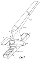
- a locking window fastener comprises a base 10, preferably formed of a metal casting, which has a central section formed with an upstanding boss 12 defining a through hole 14, the boss 12 being profiled to have a pair of shoulders 16,18 formed on respective sides of the base 10 and operating as end stops as herein-after described. Also on the central section there is defined an upstanding pin spaced from the boss 12, and an upstanding profiled lug 22 having an arcuate side face 24 spaced from and parallel to the curvature of the pin 20 to define an arcuate passage 26 therebetween, and another arcuate side face 28 spaced from and parallel to the curvature of the boss 12 to define a further arcuate passage 30 therebetween.
- the base 10 is formed with a pair of longitudinally spaced countersunk holes 32 within a recess 34, each of the holes 32 being arranged to receive a locking member such as a screw for fixing the base 10 to a window casement.
- a cover 36 is provided to seat in each of the recesses 34 to thereby cover the screws.
- a handle 40 preferably formed of a metal casting, comprises an elongate gripping part 42 integrally formed at one end with a mounting part 44.
- the latter has a through opening 46 offset from the connection with the gripping part 42, and an internal cavity 48 at the location of the end of the gripping part 42.
- the mounting part 44 is further provided with an integral nose 50 located substantially centrally between the opening 46 and the cavity 48 and extending to one side of the gripping part 42.
- the nose 50 is adapted to engage a striker (not shown) which is mounted on the window frame for a purpose hereinafter described.
- the handle 40 is mounted on the base 10 by means of a pivot pin arrangement 52 operatively located through the openings 14,46 when aligned.
- the lower face of the mounting part 44 of the handle 40 has a first projecting lug 54 formed with opposed arcuate faces 56,58 and spaced from the pivot opening 46.
- the curvature of the faces 56,58 and the spacing from the pivot opening 46 are such that the lug 54, when the handle 40 is pivotally mounted on the base 10, can locate in the groove 30 formed between the boss 12 and the lug 22 on the base 10.
- a further lug 60 is formed on the lower face of the mounting part 44 and engages the upper surface of the central part of the base 10 at the side thereof remote from the lug 22 when the handle 40 is pivotally mounted on the base 10 so as to support the handle 40.
- the latter is arranged to pivot between a closed position where the gripping part 42 is aligned substantially above one side of the base 10 with the lug 54 at the end of the passage 30 in engagement with the shoulder 16, and an open position which is determined by the movement of the lug 54 through the passage 30 into engagement with the shoulder 18, the lug 60 being profiled to be able to move past the latter and outwardly of the boss 12.
- the nose 50 of the handle 40 engages the striker on the window frame to prevent opening of the window without pivoting of the handle 40.
- a locking arrangement comprises a lock 62 having a substantially cylindrical form but having an axial opening at its lower end extending radially onto the circumference of the lock 62, whereby to define a lower end 64 somewhat of 'horseshoe' shape.
- the end 64 preferably has a metal reinforcement.
- the lug 62 Aligned with the peripheral opening, the lug 62 has cuts longitudinally along its length from the radial opening defining a finger 66.
- the lock 62 is preferably formed from a moulded plastics material with the finger 66 being biassed to deflect outwardly of the lock 62.
- the lock 62 is formed with a key receiving part 68 which is preferably separate from, and is of smaller diameter than, the main body of the lock 62, the part 68 being formed with an arrangement of through slots 70. A corresponding arrangement of slots is formed in the upper face of the main body.
- the main body of the lock 62 is also formed at its upper end, substantially diametrically opposed to the finger 66, with a longitudinally extending lug 72.
- the cavity 48 in the handle 40 is profiled to receive the lock 62 with the upper face 70 of the part 68 being accessible at the gripping part 42 through an aperture 74.
- the latter to retain the lock 62 in the cavity 48, the latter, to that side remote from the pivot opening 46, is formed with an arcuate recess 75 of increased radius, and opposite the recess 74 is provided with a further recess 76 having end seatings 77.
- the lug 72 locates in the recess 75, and the finger 66 is biassed into the recess 76.
- a locking shell 78 of suitable arcuate form is push fitted into the recess 75, having end shoulders 80 engaging on seatings (not shown) in the recess 75, and retaining the lock 62 in position.
- the lower end 64 of the lock 62 projects downwardly below the lower face of the mounting part 44 of the handle 40 so as to function as a locking part.
- the lower end 64 of the lock 62 engages around the pin 20 on the base 10.
- the lock lower end 64 can disengage from the pin 20 to enable the handle 40 to be pivoted to its open position.
- a key 82 having an operating part 84 profiled to fit through the slotted part 68 of the lock 62 through the opening 74.
- the respective slots in the part 68 and the main body have to be aligned before the key can extend into the main body and the lock operated.
- Rotation of the key 82 rotates the lock 62 within the handle 40 to the position shown in Fig. 2 and moves the lock lower end 64 around the pin 20, the respective section of the lower end 64 being so dimensioned as to engage in the arcuate passage 26 between the pin 20 and the lug 22, to such a position that the engagement between the pin 20 and the lower end 64 prevents pivoting of the handle 40 away from the closed position.
- the arrangement of the nose 50 centrally of the handle mounting part 44, with the lock axis laterally offset from the pivot axis, enables a plate of the striker to be fixed centrally on the window frame relative to the handle, which is aesthetically desirable. Also the nose 50 can move through a greater arc on pivoting of the handle and therefore can be clear of the screw holes 32 to afford ready access thereto.
- the lug 56 ensures that, in its open position, the handle 40 is retained clear of the screw openings 32 in the base 10.
- the lug 56 is operable substantially internally between the base 10 and the handle 40 to thereby further improve the aesthetics of the apparatus.
- the designs of the components may differ from that described and shown provided the components function as desired.
- the relative dimensions can be altered to suit different types of windows and window casements, and the base may be mounted on the window casement while the handle may be mounted on the window frame.
- the invention may be utilised with other closure members in fixture openings and is not necessarily restricted to windows.
- the components can be made of different materials.
- the main components may be made of plastics.
Landscapes
- Specific Sealing Or Ventilating Devices For Doors And Windows (AREA)
- Lock And Its Accessories (AREA)
Applications Claiming Priority (2)
| Application Number | Priority Date | Filing Date | Title |
|---|---|---|---|
| GB8724140 | 1987-10-14 | ||
| GB878724140A GB8724140D0 (en) | 1987-10-14 | 1987-10-14 | Fastening for closure members |
Publications (2)
| Publication Number | Publication Date |
|---|---|
| EP0312381A2 true EP0312381A2 (fr) | 1989-04-19 |
| EP0312381A3 EP0312381A3 (fr) | 1989-12-20 |
Family
ID=10625326
Family Applications (1)
| Application Number | Title | Priority Date | Filing Date |
|---|---|---|---|
| EP88309640A Withdrawn EP0312381A3 (fr) | 1987-10-14 | 1988-10-14 | Fermeture pour portes, fenêtres ou similaires |
Country Status (2)
| Country | Link |
|---|---|
| EP (1) | EP0312381A3 (fr) |
| GB (1) | GB8724140D0 (fr) |
Cited By (2)
| Publication number | Priority date | Publication date | Assignee | Title |
|---|---|---|---|---|
| AU666693B2 (en) * | 1991-12-19 | 1996-02-22 | Tarmac Construction Limited | Improvements in and relating to treatments for concrete |
| US8697002B2 (en) | 2011-10-27 | 2014-04-15 | Uop Llc | Latch for a hydroprocessing vessel and method relating thereto |
Family Cites Families (4)
| Publication number | Priority date | Publication date | Assignee | Title |
|---|---|---|---|---|
| US3899204A (en) * | 1973-09-26 | 1975-08-12 | Carl Ulrich | Washing machine and door latch |
| GB1506763A (en) * | 1975-09-12 | 1978-04-12 | Bloxvich Lock Stamping | Fastening mechanism for doors |
| IT8122292V0 (it) * | 1981-07-07 | 1981-07-07 | Lomazzo Costr Mecc | Serratura per boccaporti di imbarcazioni manovrabile dall'interno e dall'esterno. |
| GB2156893A (en) * | 1984-04-05 | 1985-10-16 | Concrete Utilities | A door lock for a lighting column |
-
1987
- 1987-10-14 GB GB878724140A patent/GB8724140D0/en active Pending
-
1988
- 1988-10-14 EP EP88309640A patent/EP0312381A3/fr not_active Withdrawn
Cited By (2)
| Publication number | Priority date | Publication date | Assignee | Title |
|---|---|---|---|---|
| AU666693B2 (en) * | 1991-12-19 | 1996-02-22 | Tarmac Construction Limited | Improvements in and relating to treatments for concrete |
| US8697002B2 (en) | 2011-10-27 | 2014-04-15 | Uop Llc | Latch for a hydroprocessing vessel and method relating thereto |
Also Published As
| Publication number | Publication date |
|---|---|
| GB8724140D0 (en) | 1987-11-18 |
| EP0312381A3 (fr) | 1989-12-20 |
Similar Documents
| Publication | Publication Date | Title |
|---|---|---|
| US8336930B2 (en) | Window sash latch | |
| US4617810A (en) | Sliding glass door lock | |
| US4671089A (en) | Door latch and deadbolt assembly | |
| US6349576B2 (en) | Lockable sash assembly | |
| CN1038777C (zh) | 碰锁装置 | |
| CA2215950C (fr) | Poignee de porte a profil surbaisse | |
| US4998423A (en) | Ring shaped hanging lock with replaceable core | |
| US4793163A (en) | Hasp-type latch and method of making and using same | |
| US5315850A (en) | Surface mounted slide bolt | |
| JPH06323050A (ja) | 掛けがねアセンブリ | |
| US4876866A (en) | Door latch and deadbolt assembly | |
| US4646547A (en) | Dead bolt combination lock | |
| US5709112A (en) | Tamperproof locking and latching mechanism for rotatable controls | |
| CN1197879A (zh) | 锁 | |
| US4784417A (en) | Door latch and deadbolt assembly | |
| US5230231A (en) | Padlock | |
| US4648643A (en) | Retrofit lever assembly for a door knob | |
| US5141268A (en) | Safety door latch bolt | |
| EP0312381A2 (fr) | Fermeture pour portes, fenêtres ou similaires | |
| US20050160775A1 (en) | Deadbolt | |
| US4788837A (en) | Hasp-type latch with combination lock | |
| EP0499740A2 (fr) | Dispositif de verrouillage | |
| GB2205604A (en) | Locking device | |
| GB2076883A (en) | Window lock | |
| WO2003102333A1 (fr) | Mecanisme de verrouillage |
Legal Events
| Date | Code | Title | Description |
|---|---|---|---|
| PUAI | Public reference made under article 153(3) epc to a published international application that has entered the european phase |
Free format text: ORIGINAL CODE: 0009012 |
|
| AK | Designated contracting states |
Kind code of ref document: A2 Designated state(s): BE DE ES FR GB IT NL |
|
| PUAL | Search report despatched |
Free format text: ORIGINAL CODE: 0009013 |
|
| AK | Designated contracting states |
Kind code of ref document: A3 Designated state(s): BE DE ES FR GB IT NL |
|
| STAA | Information on the status of an ep patent application or granted ep patent |
Free format text: STATUS: THE APPLICATION IS DEEMED TO BE WITHDRAWN |
|
| 18D | Application deemed to be withdrawn |
Effective date: 19900621 |