EP0312385A2 - Oberflächenbehandlung durch Coronaeffekt und dadurch behandelte Luftfahrzeugcockpithaube - Google Patents
Oberflächenbehandlung durch Coronaeffekt und dadurch behandelte Luftfahrzeugcockpithaube Download PDFInfo
- Publication number
- EP0312385A2 EP0312385A2 EP88309646A EP88309646A EP0312385A2 EP 0312385 A2 EP0312385 A2 EP 0312385A2 EP 88309646 A EP88309646 A EP 88309646A EP 88309646 A EP88309646 A EP 88309646A EP 0312385 A2 EP0312385 A2 EP 0312385A2
- Authority
- EP
- European Patent Office
- Prior art keywords
- canopy
- transparency
- cord
- corona discharge
- jig
- Prior art date
- Legal status (The legal status is an assumption and is not a legal conclusion. Google has not performed a legal analysis and makes no representation as to the accuracy of the status listed.)
- Granted
Links
Images


Classifications
-
- B—PERFORMING OPERATIONS; TRANSPORTING
- B29—WORKING OF PLASTICS; WORKING OF SUBSTANCES IN A PLASTIC STATE IN GENERAL
- B29C—SHAPING OR JOINING OF PLASTICS; SHAPING OF MATERIAL IN A PLASTIC STATE, NOT OTHERWISE PROVIDED FOR; AFTER-TREATMENT OF THE SHAPED PRODUCTS, e.g. REPAIRING
- B29C59/00—Surface shaping of articles, e.g. embossing; Apparatus therefor
- B29C59/10—Surface shaping of articles, e.g. embossing; Apparatus therefor by electric discharge treatment
- B29C59/103—Surface shaping of articles, e.g. embossing; Apparatus therefor by electric discharge treatment of profiled articles, e.g. hollow or tubular articles
-
- B—PERFORMING OPERATIONS; TRANSPORTING
- B29—WORKING OF PLASTICS; WORKING OF SUBSTANCES IN A PLASTIC STATE IN GENERAL
- B29C—SHAPING OR JOINING OF PLASTICS; SHAPING OF MATERIAL IN A PLASTIC STATE, NOT OTHERWISE PROVIDED FOR; AFTER-TREATMENT OF THE SHAPED PRODUCTS, e.g. REPAIRING
- B29C59/00—Surface shaping of articles, e.g. embossing; Apparatus therefor
- B29C59/10—Surface shaping of articles, e.g. embossing; Apparatus therefor by electric discharge treatment
- B29C59/106—Surface shaping of articles, e.g. embossing; Apparatus therefor by electric discharge treatment the electrodes being placed on the same side of the material to be treated
-
- B—PERFORMING OPERATIONS; TRANSPORTING
- B64—AIRCRAFT; AVIATION; COSMONAUTICS
- B64C—AEROPLANES; HELICOPTERS
- B64C1/00—Fuselages; Constructional features common to fuselages, wings, stabilising surfaces or the like
- B64C1/06—Frames; Stringers; Longerons ; Fuselage sections
-
- B—PERFORMING OPERATIONS; TRANSPORTING
- B64—AIRCRAFT; AVIATION; COSMONAUTICS
- B64C—AEROPLANES; HELICOPTERS
- B64C1/00—Fuselages; Constructional features common to fuselages, wings, stabilising surfaces or the like
- B64C1/32—Severable or jettisonable parts of fuselage facilitating emergency escape
-
- B—PERFORMING OPERATIONS; TRANSPORTING
- B64—AIRCRAFT; AVIATION; COSMONAUTICS
- B64D—EQUIPMENT FOR FITTING IN OR TO AIRCRAFT; FLIGHT SUITS; PARACHUTES; ARRANGEMENT OR MOUNTING OF POWER PLANTS OR PROPULSION TRANSMISSIONS IN AIRCRAFT
- B64D25/00—Emergency apparatus or devices, not otherwise provided for
- B64D25/08—Ejecting or escaping means
- B64D25/10—Ejector seats
-
- H—ELECTRICITY
- H01—ELECTRIC ELEMENTS
- H01T—SPARK GAPS; OVERVOLTAGE ARRESTERS USING SPARK GAPS; SPARKING PLUGS; CORONA DEVICES; GENERATING IONS TO BE INTRODUCED INTO NON-ENCLOSED GASES
- H01T19/00—Devices providing for corona discharge
Definitions
- This invention relates to corona discharge surface treatment, and aircraft cockpit canopies so treated.
- a particular, but not exclusive, application of the invention is in connection with aircrew escape systems which employ explosive cord arrangements located to aircraft canopy transparencies to cause fracture and break-up of the transparency when a crew member requires to make an emergency exit from the aircraft.
- 'MDC' An aircrew escape system using a form of explosive cord known as 'Miniature Detonating Cord' (hereafter referred to as 'MDC') is disclosed in British Patent No. 1,383,513.
- This prior invention provides an arrangement wherein an aircraft cockpit canopy includes detonating cord which is located around the periphery of the canopy transparency but is further extended in loop configuration across the surface of the transparency away from the periphery in a predetermined pattern particularly concentrated in the area through which the escaping crew member will pass on ejection.
- the periphery cord in this arrangement is maintained in contact with the transparency by mechanical retaining means that cord portion which extends across the surface of the transparency must rely on being adhesively bonded to the surface.
- the efficiency of the detonation effect will be dependent on a number of factors not least of which is the efficiency of the adhesive bond, whatever cord type is used.
- the cord used for the surface pattern is preferably that known as D-cord, that is, it is D-shaped in cross-section to provide a flat adhesive contact face.
- the cord may be contained within a protective shrinkable polyolefin sleeve for example.
- a circular crosssectional cord to be contained in an elastomer back-up extrusion. Whatever arrangement is employed, high adhesion integrity is essential.
- the preferred material for the transparency is an acrylic material.
- the adhesive employed may not be able to 'wet' the surface effectively.
- this problem was sought to be solved by the technique of abrading the acrylic surface by appropriate means, such as 'wet and dry' paper of suitable grade, in a pattern corresponding to that followed by the cord and which is proven in practice to achieve a bond at least comparable with the strength of bond achieved by the adhesive with the polyolefin sleeve or elastomer extrusion containing the cord.
- This practice of abrading is a manual operation utilising, ideally, an abrading 'stencil type' template.
- Corona discharge surface treatment of web materials is well-known and the technique has been applied also to shaped bodies, as is disclosed e.g. in GB-A-2,ll4,377.
- this and other prior art proposals suffer from the drawbacks of requiring complicated and expensive arrangements of controlling the areas of the workpiece to be treated and are not suitable to pretreat aircraft cockpit canopies.
- apparatus for electrically pre-treating selected areas of an article by corona discharge comprising an electrically non-conductive jig shaped to conform with the internal shape of and to mount the article, one or more rebates in an external surface of said jig of a shape, size and position corresponding to said selected areas, electrodes located in said rebates at a depth arranged so that a predetermined gap will be defined between said electrodes and the internal surface of the article and means to connect said electrodes and said article to opposite polarity terminals of a voltage generator so that in use the article to be pre-treated may be placed on the jig such that it is in contact therewith except at the selected areas and a potential difference may be applied between the article and the electrodes, to form a corona discharge across said article at said selected areas.
- said jig includes bores therethrough for connection to a pump for removing the gaseous ionisation products of the corona discharge trapped between the jig and the article.
- the article to be treated may be, for example, an aircraft cockpit canopy and the rebate and the electrode may then be shaped to correspond to the shape of an MDC to be adhesively attached to the inner surface of the canopy.
- a method of applying an adhesively attachable detonating cord arrangement to an aircraft canopy transparency including the steps of modifying at least a portion of the canopy transparency to give an adhesive receptive surface, forming the detonating cord arrangement into the required configuration, applying a curable adhesive to the adhesion face of the detonating cord arrangement, offering up said cord arrangement to the transparency surface and affiing the cord, still in the desired configuration to the transparency adhesive receptive surface, removing the template and curing the adhesive, characterised in that the adhesive receptive surface is obtained by subjecting at least that portion of the transparency surface to which the detonating cord is attached to a corona dscharge process, usng apparatus according to any of the preceding statements of the invention.
- an aircraft cockpit canopy with detonating cord to facilitate fracture and break-up of the canopy transparency for aircrew emergency ejection purposes the detonating cord being located around the periphery of the transparency and extending in loop configuration across the surface of the transparency away from the periphery, being laid in predetermined pattern particularly concentrated in the areas through which the escaping crew member will pass on ejection, at least a portion of the detonating cord being adhesively attached to said transparency, said transparency having an adhesive receptive surface provided by means of a corona discharge process.
- Corona discharge is achieved by increasing an applied voltage between an electrode and a counter-electrode until the threshold value for electrical breakdown of the air gap is exceeded, as a result of which the air is ionised and becomes plasma.
- a suitable transparency material as in the present application, is interposed relative to the electrodes to maintain a suitable air gap, when subject to an electrical bombardment will result in a surface which has an increased surface energy, is more wettable and more adhesive receptive.
- the surface may be cleaned as a result of the ionisation to assist the adhesion even further.
- an aircraft cockpit canopy 1 has a canopy transparency 2 which is bounded by a rear arch 3, a forward arch 4 and canopy sill structure 5.
- a run of miniature detonating cord 7 laid in a loop configuration leading out a the peripheral cord run 8 near the forward arch 4.
- the loop configuration is shown in broken line to indicate that the cord 7 is laid on the inner surface of the transparency 2; it has a series of more or less sharp bends 9 to act as crack initiators when the cord is detonated.
- the peripheral cord run 8 extends around the periphery of the canopy transparency but has been largely omitted.
- Figure 2 shows a localised view of the loop configuration of cord. It is inverted a view on the inner surface of the transparency.
- the transparency surface is abraded in conformity with the MDC configuration to give an adhesive receptive-surface. For reasons of optical clarity little deviation of the abraded area can be permitted since that can lead to unacceptable obstruction of vision.
- the inner surface is subjected to a corona discharge treatment to stimulate surface energy and enhance wettability.
- a corona discharge treatment to stimulate surface energy and enhance wettability.
- the benefit of this treatment is that the high gloss surface of the transparency is unimpaired: since the treatment imparts no visible change in the surface characteristics and maintains high optical clarity. It will be appreciated that this treatment may therefore be applied either,
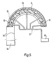
- Figures 3 and 5 show a corona discharge apparatus comprising a jig 10 made of glass-reinforced plastics which is shaped to correspond to the inner surface of the transparent canopy.
- the jig 10 has a plurality of rebates 11, each containing countersunk corona discharge electrodes 12. Bores 13 are provided through the jig 10 for a purpose described below.
- the electrodes 12 and the canopy 2 are in use connected to a high voltage generator 14 via flexible high voltage leads 15.
- the bores 13 are connected to an extraction pump 16 via a network of pipes 17.
- the rebates 11 are each of a depth to ensure that the exposed face of the electrodes 12 are typically 1.5 mm below the outer surface of the jig 10.
- the rebates 11 and the electrodes 12 are shaped to correspond with the MDC cord 7.
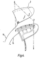
- Figure 4 shows an alternative embodiment in which the electrode 12 are not shaped to correspond with the MDC cord 7 but are instead formed as two broad strips.
- FIG. 5 is a crosssectional view of Figure 3 through a plane A-A. This same view also corresponds closely with the view which would be seen in a plane A-A through the alternative embodiment of Figure 4 except that the two uppermost electrodes will be broader than those shown in Figure 5.
- each electrode is shown as being fixed inside a rebate directly to the surface of the jig, it may actually be attached to a thin layer of a sponge-like material which is interposed between the electrode and the surface of the jig to provide a constant gap and thus to ensure that a consistent corona discharge is maintained between each electrode and the canopy.
- a transparent canopy 2 is placed on top of the jig 10 so that the outer surface of the jig 10 makes uniform contact with the canopy 2 so as in effect to form a mask for the canopy except at the locations of the rebates 11 containing the electrodes 12.
- the high voltage leads 15 and pipes 17 are connected to electrodes 12 and bores 13, respectively.
- the high voltage generator 14 is switched on and the potential difference between the electrodes 12 and the canopy 2 causes a corona discharge therebetween.
- the voltage generator 14 may be of the type manufactured by Sherman Generators which typically operate at voltages between 7 to 28 kV and at a frequency of 17 KHz.
- the canopy 2 is treated by corona discharge over a localised area which corresponds to the shape of the electrodes 12 and which is consequently the same shape as the MDC 7. It will be noted that a complex shape is treated by corona discharge in this way; and moreover that there are no moving parts; nor is an enclosure required as the treatment may take place at normal pressures and in a normal (ambient) atmosphere.
- the extraction pump 16 is switched on and pumps highly ionised ozone gas away from the region of canopy 2 through the bores 13.
- Ozone gas is a by-product of corona discharge and will damage the surface of the canopy if allowed to accumulate in sufficient concentrations.
- a MDC 7 is bonded in place on the treated part of the canopy, using an appropriate adhesive such as Raychem S100S.
- the MDC 7 and the adhesive have to be accurately positioned on the treated area of the canopy, otherwise its bonding will be less effective.
- the treated areas are not visibly different from the untreated area so that it will not be readily apparent as to where the adhesive and the MDC are to be applied.
- This difficulty may be overcome by placing the MDC, adhesive side up, into the rebates 11 of the jig 10 after pretreatment of the canopy 2 and then replacing the canopy on the jig using reference marks on the canopy and jig for accurate alignment.
- the MDC 7 is then bonded accurately onto the pre-treated surface of the canopy 2.
- the embodiment of Figure 4 may be used to treat the canopy in which case the accuracy with which the MDC is positioned on the canopy is not as critical as in the embodiment of Figure 3.
- the canopy is treated in two large strips which are each broad enough to allow for minor deviations in the position of the MDC.
Landscapes
- Engineering & Computer Science (AREA)
- Aviation & Aerospace Engineering (AREA)
- Mechanical Engineering (AREA)
- Physics & Mathematics (AREA)
- Plasma & Fusion (AREA)
- Business, Economics & Management (AREA)
- Emergency Management (AREA)
- Treatments Of Macromolecular Shaped Articles (AREA)
- Chemical Or Physical Treatment Of Fibers (AREA)
- Adhesives Or Adhesive Processes (AREA)
- Application Of Or Painting With Fluid Materials (AREA)
- Threshing Machine Elements (AREA)
Priority Applications (1)
| Application Number | Priority Date | Filing Date | Title |
|---|---|---|---|
| AT88309646T ATE74475T1 (de) | 1987-10-14 | 1988-10-14 | Oberflaechenbehandlung durch coronaeffekt und dadurch behandelte luftfahrzeugcockpithaube. |
Applications Claiming Priority (2)
| Application Number | Priority Date | Filing Date | Title |
|---|---|---|---|
| GB878724078A GB8724078D0 (en) | 1987-10-14 | 1987-10-14 | Aircrew escape system |
| GB8724078 | 1987-10-14 |
Publications (3)
| Publication Number | Publication Date |
|---|---|
| EP0312385A2 true EP0312385A2 (de) | 1989-04-19 |
| EP0312385A3 EP0312385A3 (en) | 1990-03-14 |
| EP0312385B1 EP0312385B1 (de) | 1992-04-01 |
Family
ID=10625299
Family Applications (1)
| Application Number | Title | Priority Date | Filing Date |
|---|---|---|---|
| EP19880309646 Expired - Lifetime EP0312385B1 (de) | 1987-10-14 | 1988-10-14 | Oberflächenbehandlung durch Coronaeffekt und dadurch behandelte Luftfahrzeugcockpithaube |
Country Status (5)
| Country | Link |
|---|---|
| US (1) | US4892271A (de) |
| EP (1) | EP0312385B1 (de) |
| AT (1) | ATE74475T1 (de) |
| DE (1) | DE3869727D1 (de) |
| GB (1) | GB8724078D0 (de) |
Families Citing this family (3)
| Publication number | Priority date | Publication date | Assignee | Title |
|---|---|---|---|---|
| US5051586A (en) * | 1990-04-18 | 1991-09-24 | Sabreen Scott R | Corona charging of plastic and apparatus therefor |
| US20040055698A1 (en) * | 2002-09-24 | 2004-03-25 | Tran Hai Q. | Method of improving lamination quality by treating media with plasma |
| JP5533966B2 (ja) * | 2012-09-14 | 2014-06-25 | ダイキン工業株式会社 | 空気清浄機 |
Family Cites Families (11)
| Publication number | Priority date | Publication date | Assignee | Title |
|---|---|---|---|---|
| US2876358A (en) * | 1957-04-18 | 1959-03-03 | Bradley Container Corp | Method of and apparatus for treating surfaces of thermoplastic containers by corona discharge |
| GB877908A (en) * | 1959-05-21 | 1961-09-20 | American Can Co | Treating of thermoplastic tubes |
| BE635548A (de) * | 1962-07-31 | |||
| US3291711A (en) * | 1963-03-12 | 1966-12-13 | Du Pont | Treating electrode and process |
| GB1100414A (en) * | 1964-05-19 | 1968-01-24 | Ici Ltd | Treatment of plastics surfaces with an electrical discharge to improve their bonding properties |
| US3600122A (en) * | 1966-03-11 | 1971-08-17 | Surface Aviat Corp | Method of grafting ethylenically unsaturated monomer to a polymeric substrate |
| GB1212620A (en) * | 1968-10-15 | 1970-11-18 | Ethyl Corp | Electrode for discharge treatment of plastics |
| GB1383513A (en) * | 1971-06-10 | 1974-02-12 | Hawker Siddeley Aviation Ltd | Aircrew escape systems |
| GB2022323A (en) * | 1978-06-03 | 1979-12-12 | Ferrarini & Benelli Srl | Corona discharge surface treatment apparatus for sheet materials |
| GB2114377B (en) * | 1982-01-29 | 1985-11-27 | Klaus Kalwar | Process and apparatus for the electrical corona treatment of materials in web form or shaped bodies, only on one side thereof |
| DE3622737C1 (de) * | 1986-07-05 | 1987-10-08 | Klaus Kalwar | Verfahren zur Korona-Behandlung von bahnfoermigen Materialien sowie Vorrichtung zur Durchfuehrung des Verfahrens |
-
1987
- 1987-10-14 GB GB878724078A patent/GB8724078D0/en active Pending
-
1988
- 1988-10-11 US US07/255,398 patent/US4892271A/en not_active Expired - Fee Related
- 1988-10-14 AT AT88309646T patent/ATE74475T1/de active
- 1988-10-14 DE DE8888309646T patent/DE3869727D1/de not_active Expired - Fee Related
- 1988-10-14 EP EP19880309646 patent/EP0312385B1/de not_active Expired - Lifetime
Also Published As
| Publication number | Publication date |
|---|---|
| EP0312385B1 (de) | 1992-04-01 |
| US4892271A (en) | 1990-01-09 |
| EP0312385A3 (en) | 1990-03-14 |
| DE3869727D1 (de) | 1992-05-07 |
| GB8724078D0 (en) | 1988-02-17 |
| ATE74475T1 (de) | 1992-04-15 |
Similar Documents
| Publication | Publication Date | Title |
|---|---|---|
| EP0839635B1 (de) | Verfahren zum Reparieren eines Kompositschichtstoffes | |
| DE3663093D1 (en) | Photo-initiator systems for free-radical polymerisations | |
| KR20160102767A (ko) | 플렉시블 패널 곡면 합착 방법 | |
| DK208884A (da) | Laminatafsnit med afdaekning og hjaelpemiddel til aftraekning af denne | |
| EP0312385B1 (de) | Oberflächenbehandlung durch Coronaeffekt und dadurch behandelte Luftfahrzeugcockpithaube | |
| DK666088A (da) | Afrivningshjaelpemiddel og anvendelse deraf | |
| AR242551A1 (es) | Un metodo y aparato para el corte de vidrio a lo largo de una linea de corte seleccionada mientras que se mantiene sus propiedades opticas. | |
| JPS56118430A (en) | Vinyl chloride resin molded article in which surface is modified | |
| AU8227698A (en) | Method and apparatus for decontamination of fluids | |
| AR000546A1 (es) | Método para cortar a un largo predeterminado un laminado de caucho no curado y aparato para llevar ala practica dicho método | |
| KR20170091287A (ko) | 플렉서블 패널 곡면 합착 방법 | |
| US3902945A (en) | Method of making an aircrew escape systems | |
| DK1387901T3 (da) | Fremgangsmåde og apparat il behandlinger af tekstilmaterialer | |
| JP2000025948A (ja) | 静電浮上搬送装置 | |
| MY100652A (en) | Ionizing plasma lubricant method | |
| GR852294B (de) | ||
| EP0788870A3 (de) | Verfahren zur Oberflächenbehandlung von vulkanisiertem Gummi und Verfahren zur Herstellung von Verbundmaterialien auf Gummibasis | |
| DE3677437D1 (de) | Verfahren und vorrichtung mit ein- und ausgangsbehandlungskammern zum laminieren unter reduziertem druck. | |
| BR8306717A (pt) | Processo para a operacao de um tear a jato de ar | |
| KR880006068A (ko) | 찢어짐방지 바람막이 및 그 제조방법 | |
| ES2182229T3 (es) | Procedimiento de de un material sellante. | |
| ES523798A0 (es) | Procedimiento para la produccion de articulos de caucho reforzados con cordon de acero. | |
| KR102561496B1 (ko) | 초박 유리 처리장치 및 초박 유리 처리방법 | |
| DE59709130D1 (de) | Verfahren sowie Vorrichtung zum Längsaufbringen von mindestens einer Folie auf ein Kabelprodukt | |
| EP1296825A1 (de) | Verglasung |
Legal Events
| Date | Code | Title | Description |
|---|---|---|---|
| PUAI | Public reference made under article 153(3) epc to a published international application that has entered the european phase |
Free format text: ORIGINAL CODE: 0009012 |
|
| AK | Designated contracting states |
Kind code of ref document: A2 Designated state(s): AT CH DE FR GB IT LI NL SE |
|
| PUAL | Search report despatched |
Free format text: ORIGINAL CODE: 0009013 |
|
| AK | Designated contracting states |
Kind code of ref document: A3 Designated state(s): AT CH DE FR GB IT LI NL SE |
|
| 17P | Request for examination filed |
Effective date: 19900903 |
|
| 17Q | First examination report despatched |
Effective date: 19910410 |
|
| GRAA | (expected) grant |
Free format text: ORIGINAL CODE: 0009210 |
|
| ITF | It: translation for a ep patent filed | ||
| AK | Designated contracting states |
Kind code of ref document: B1 Designated state(s): AT CH DE FR GB IT LI NL SE |
|
| REF | Corresponds to: |
Ref document number: 74475 Country of ref document: AT Date of ref document: 19920415 Kind code of ref document: T |
|
| ET | Fr: translation filed | ||
| REF | Corresponds to: |
Ref document number: 3869727 Country of ref document: DE Date of ref document: 19920507 |
|
| RAP4 | Party data changed (patent owner data changed or rights of a patent transferred) |
Owner name: BRITISH AEROSPACE PUBLIC LIMITED COMPANY |
|
| REG | Reference to a national code |
Ref country code: CH Ref legal event code: PFA Free format text: BRITISH AEROSPACE PUBLIC LIMITED COMPANY |
|
| PLBE | No opposition filed within time limit |
Free format text: ORIGINAL CODE: 0009261 |
|
| STAA | Information on the status of an ep patent application or granted ep patent |
Free format text: STATUS: NO OPPOSITION FILED WITHIN TIME LIMIT |
|
| 26N | No opposition filed | ||
| EAL | Se: european patent in force in sweden |
Ref document number: 88309646.3 |
|
| PGFP | Annual fee paid to national office [announced via postgrant information from national office to epo] |
Ref country code: AT Payment date: 20001113 Year of fee payment: 13 |
|
| PGFP | Annual fee paid to national office [announced via postgrant information from national office to epo] |
Ref country code: FR Payment date: 20001114 Year of fee payment: 13 Ref country code: DE Payment date: 20001114 Year of fee payment: 13 |
|
| PGFP | Annual fee paid to national office [announced via postgrant information from national office to epo] |
Ref country code: NL Payment date: 20001127 Year of fee payment: 13 |
|
| PGFP | Annual fee paid to national office [announced via postgrant information from national office to epo] |
Ref country code: GB Payment date: 20001206 Year of fee payment: 13 |
|
| PGFP | Annual fee paid to national office [announced via postgrant information from national office to epo] |
Ref country code: CH Payment date: 20010111 Year of fee payment: 13 |
|
| PGFP | Annual fee paid to national office [announced via postgrant information from national office to epo] |
Ref country code: SE Payment date: 20010205 Year of fee payment: 13 |
|
| PG25 | Lapsed in a contracting state [announced via postgrant information from national office to epo] |
Ref country code: GB Free format text: LAPSE BECAUSE OF NON-PAYMENT OF DUE FEES Effective date: 20011014 Ref country code: AT Free format text: LAPSE BECAUSE OF NON-PAYMENT OF DUE FEES Effective date: 20011014 |
|
| PG25 | Lapsed in a contracting state [announced via postgrant information from national office to epo] |
Ref country code: SE Free format text: LAPSE BECAUSE OF NON-PAYMENT OF DUE FEES Effective date: 20011015 |
|
| PG25 | Lapsed in a contracting state [announced via postgrant information from national office to epo] |
Ref country code: LI Free format text: LAPSE BECAUSE OF NON-PAYMENT OF DUE FEES Effective date: 20011031 Ref country code: CH Free format text: LAPSE BECAUSE OF NON-PAYMENT OF DUE FEES Effective date: 20011031 |
|
| REG | Reference to a national code |
Ref country code: GB Ref legal event code: IF02 |
|
| PG25 | Lapsed in a contracting state [announced via postgrant information from national office to epo] |
Ref country code: NL Free format text: LAPSE BECAUSE OF NON-PAYMENT OF DUE FEES Effective date: 20020501 |
|
| EUG | Se: european patent has lapsed |
Ref document number: 88309646.3 |
|
| GBPC | Gb: european patent ceased through non-payment of renewal fee |
Effective date: 20011014 |
|
| REG | Reference to a national code |
Ref country code: CH Ref legal event code: PL |
|
| PG25 | Lapsed in a contracting state [announced via postgrant information from national office to epo] |
Ref country code: FR Free format text: LAPSE BECAUSE OF NON-PAYMENT OF DUE FEES Effective date: 20020628 |
|
| NLV4 | Nl: lapsed or anulled due to non-payment of the annual fee |
Effective date: 20020501 |
|
| PG25 | Lapsed in a contracting state [announced via postgrant information from national office to epo] |
Ref country code: DE Free format text: LAPSE BECAUSE OF NON-PAYMENT OF DUE FEES Effective date: 20020702 |
|
| REG | Reference to a national code |
Ref country code: FR Ref legal event code: ST |
|
| PG25 | Lapsed in a contracting state [announced via postgrant information from national office to epo] |
Ref country code: IT Free format text: LAPSE BECAUSE OF NON-PAYMENT OF DUE FEES;WARNING: LAPSES OF ITALIAN PATENTS WITH EFFECTIVE DATE BEFORE 2007 MAY HAVE OCCURRED AT ANY TIME BEFORE 2007. THE CORRECT EFFECTIVE DATE MAY BE DIFFERENT FROM THE ONE RECORDED. Effective date: 20051014 |