EP0312497A1 - Transportanlage, insbesondere Sessellift oder Kabinenseilbahn - Google Patents
Transportanlage, insbesondere Sessellift oder Kabinenseilbahn Download PDFInfo
- Publication number
- EP0312497A1 EP0312497A1 EP88810690A EP88810690A EP0312497A1 EP 0312497 A1 EP0312497 A1 EP 0312497A1 EP 88810690 A EP88810690 A EP 88810690A EP 88810690 A EP88810690 A EP 88810690A EP 0312497 A1 EP0312497 A1 EP 0312497A1
- Authority
- EP
- European Patent Office
- Prior art keywords
- station
- zone
- cable
- transport installation
- cabins
- Prior art date
- Legal status (The legal status is an assumption and is not a legal conclusion. Google has not performed a legal analysis and makes no representation as to the accuracy of the status listed.)
- Granted
Links
- 238000009434 installation Methods 0.000 title claims abstract description 16
- 230000008878 coupling Effects 0.000 claims description 9
- 238000010168 coupling process Methods 0.000 claims description 9
- 238000005859 coupling reaction Methods 0.000 claims description 9
- 230000000630 rising effect Effects 0.000 claims description 4
- 230000001174 ascending effect Effects 0.000 description 3
- 238000010276 construction Methods 0.000 description 2
- 230000000694 effects Effects 0.000 description 1
- 238000012876 topography Methods 0.000 description 1
Images

Classifications
-
- B—PERFORMING OPERATIONS; TRANSPORTING
- B61—RAILWAYS
- B61B—RAILWAY SYSTEMS; EQUIPMENT THEREFOR NOT OTHERWISE PROVIDED FOR
- B61B11/00—Ski lift, sleigh lift or like trackless systems with guided towing cables only
-
- B—PERFORMING OPERATIONS; TRANSPORTING
- B61—RAILWAYS
- B61B—RAILWAY SYSTEMS; EQUIPMENT THEREFOR NOT OTHERWISE PROVIDED FOR
- B61B12/00—Component parts, details or accessories not provided for in groups B61B7/00 - B61B11/00
- B61B12/02—Suspension of the load; Guiding means, e.g. wheels; Attaching traction cables
- B61B12/022—Vehicle receiving and dispatching devices
Definitions
- the invention relates to an installation according to the preamble of claim 1.
- the invention is described below as being applied to a detachable single-cable gondola lift, but it is clear that it also applies to similar installations such as, for example, chairlifts and monocable or bicable cable-cars.
- the present invention therefore aims to remedy these drawbacks and allow the realization of an installation adaptable to very variable operating conditions on a small area.
- the installation according to the invention is characterized as indicated in the characterizing part of claim 1.
- This new layout of the buildings as well as the choice of electro-mechanical equipment makes it possible to move the loaded cabins in the phase where they are separated from the conveyor cable.
- This system gives the possibility to embark respectively to disembark in different zones located essentially one above the other, that is to say at different levels. This makes it possible to use one or the other or all of the embarkation or disembarkation areas respectively. For example, when leaving a winter station in the morning, the crowds are higher in a lower level, later in the day, when the installation is occupied by the users of the runway assigned to this installation, the boarding often makes more sense at a higher level.
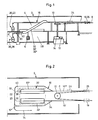
- the valley station of a single cable gondola is a building 2 with a main floor 4.
- the cabins 6 which are provided for two to twelve people can be coupled in a known manner to a cable 8.
- This aerial cable 8 goes into building 2 on a deflection pulley 10 driven in rotation by a motor 12, by a gearbox 14.
- a rail system 16 is arranged on the ceiling of the main stage 4, the rails essentially forming a U with the sections 16 ′, 16 ⁇ , 16 ′′′.
- This main stage 4 contains different zones, that is to say a decoupling zone 18, a landing zone 20, a boarding zone 22 adjacent to the landing zone 20, a waiting zone 24 and a waiting zone. coupling 26.
- the decoupling zone 18 is where the cabins 6 arriving from the mountain station are decoupled from the cable 8 and placed on the section 16 ′ of the rail system 16; they move towards the landing zone 20, gradually losing their speed, this due to friction or to the effect of a braking installation which is usually expected. In case the cabs slow down too much, just push them manually to the desired location.
- the cabins 6 When arriving at the landing area 20, the cabins 6 are stopped automatically or manually; passengers leave cabins 6 and possibly take their skis or luggage from a ski or luggage rack attached to the outside of each cabin 6. Cabins 6 are then moved to boarding area 22 where the new passengers load their skis or luggage and take their places. It may not be planned to separate the building into a first part for passengers wishing to the journey and in a second part for the passengers who have just made the journey; in these cases, the embarkation and disembarkation zones are identical. The cabins 6 occupied are subsequently moved to the waiting area 24, from where they are shipped, generally automatically and at regular intervals, to the coupling area 26. Again secured to the cable 8, the cabins 6 then leave the station. These installations and their operating mode are known.
- the building 2 has a secondary floor 28 located at a different plane than the main floor 4, in the particular case below this main floor 4.
- a second rail system 30, 30 ′, 30 ⁇ , 30 ′′′, also forming a U, is arranged on the ceiling of the secondary stage 28.
- a system of conveyors 32 arranged obliquely in our example and which comprises an ascending section 32 ′ and a descending section 32 ⁇ , connects a section 34 of the first rail system 16 to the section 30 ′ of the second rail system 30.
- a switch arranged in the section 16 ′ alternately serves the section 34 or the section 16 ⁇ .
- the secondary floor 28 there is a second landing area 36 and a second loading area 38, these two areas can also be combined as on the main floor, as well as a second waiting area 40.
- a part of the cabins 6 arriving on the first rail system 16 is selected automatically or manually and returned to the descending section 32 ′ of the conveyor system 32 , which descends the cabins 6 to the secondary floor 28. Leaving this section 32 ′, the cabins 6 arrive using the second rail system 30 towards the second disembarkation area 36 or embarkation 38 respectively where the exchange of passengers and / or goods is carried out. Then the cabins 6 are moved to the second waiting area 40 from where they are accelerated towards the section 32 ⁇ amount of the conveyor system 32 at set intervals. Having returned to the main floor 4, the cabins 6 thread through another switch between the cabins coming from the first boarding area 22, and they continue their journey as the cabins having remained on the main floor 4 .
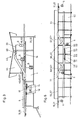
- Figure 3 shows a corresponding mountain station.
- the main floor is designed essentially as described for the valley station building and has the same figures.
- the secondary stage 44 is located above the main stage.
- the rail systems of the two floors are also connected by a conveyor system 46, with the difference that the cabins 6 arriving at the station are directed first to the rising section 46 ′, then to the second disembarkation area 48, respectively embarkation 50 and finally to the descending section 46 ⁇ of the conveyor system 46.
- the operating mode is similar to that of the station in FIGS. 1 and 2.
- Figures 4 and 5 show an intermediate station with a building 52 which can be divided into parts closed in the middle and parts open at the ends.
- the main floor 54 is located essentially at the level of the neighboring land, thus forming the ground floor of the building 52. Cables 8 and 9 cross the building 52 in opposite directions.
- a first system of transfer rails 56, 57 is arranged in a known manner on the ceiling of the main stage 54 and connects the decoupling zones 18 respectively 19 to the coupling zones 20 respectively 21.
- Two landing zones 58, 59 and two Boarding areas 60, 61 are located in the middle of the building 52.
- the secondary floor 62 is located above the main floor 54, forming the first floor of the building 52.
- the second rail system 64, 65 is arranged at the ceiling of the secondary stage 62.
- Two conveyor systems 66, 67 each comprising an ascending section 66 ′, 67 ′ and a descending section 66 ⁇ , 67 ⁇ connect the secondary stage 62 to the main stage 54.
- Two zones of disembarkation 69, 69 and two embarkation zones 70, 71 are located in the center of the secondary stage 62.
- the cabins 6 arriving from the left are separated from the cable 8 in the decoupling zone 18. They continue their journey on the rail system 56 to a switch 72 from which a part of the cabins 6 follows the rail system 56, while the rest of the cabins 6 heads towards the rising section 66 ′ of the conveyor system 66 to reach the secondary stage 62.
- the cabins 6 of the main stage 54 pass through the zone of disembarkation 58 and the embarkation zone 60 and leave the rail system 56 in the coupling zone 20.
- the cabins 6 of the secondary stage 62 pass through the disembarkation zone 68 and by the embarkation zone 70 and return then the first rail system 56 at the main level 54 using the descending section 66 ⁇ of the conveyor system 66.
- the cabins 6 coming from the right move analogously from the decoupling 19 to the coupling zone 21, passing through the station either on the main stage 54 on the rail system 57 and by serving the landing zones 59 and boarding zones 61 either on the secondary stage using the ascending section 67 ′ and descending section 67 ⁇ of the conveyor system 67 and by serving the landing areas 69 and boarding areas 71.
- Figure 6 finally shows an intermediary station which specially meets the needs of urban transport. It corresponds to the station in Figures 4 and 5 also bearing the same figures with the only difference that the main floor is above the secondary floor, the last being located at the level of the neighboring land and thus forming the ground floor. - floor of the building so that the cabins must first go down and then go up using the conveyor system. It is obvious that it will be more comfortable for passengers to disembark and board at the secondary level and it will therefore be logical to use it first and to reserve the additional use of the main floor during peak hours.
- Garage tracks 74 can be arranged on the main floor and / or on the secondary floor, but to make the best use of the space in the buildings they are provided according to FIG. 2 preferably at the secondary level below respectively above the lateral sections of the main floor rail systems.
- the conveyor systems being arranged obliquely in the embodiment to which the description relates by way of example can be replaced by vertical conveyor systems.
- Vehicles can be suspended or hung in conveyor systems. But it is also possible to place them in a conveyor system consisting essentially of a carpet, escalator or elevator.
- the new station which gives the possibility to empty respectively to fill cabins, seats or skips at different levels and to favor one or the other therefore allows the construction of a relatively compact building and facilitates operation rational of the transport system.
Landscapes
- Engineering & Computer Science (AREA)
- Transportation (AREA)
- Mechanical Engineering (AREA)
- Types And Forms Of Lifts (AREA)
- Lift-Guide Devices, And Elevator Ropes And Cables (AREA)
Priority Applications (1)
| Application Number | Priority Date | Filing Date | Title |
|---|---|---|---|
| AT88810690T ATE70011T1 (de) | 1987-10-15 | 1988-10-07 | Transportanlage, insbesondere sessellift oder kabinenseilbahn. |
Applications Claiming Priority (3)
| Application Number | Priority Date | Filing Date | Title |
|---|---|---|---|
| CH4044/87 | 1987-10-15 | ||
| CH4044/87A CH674492A5 (de) | 1987-10-15 | 1987-10-15 | |
| CH202/89A CH680060A5 (en) | 1987-10-15 | 1989-01-24 | Public transportation system - uses chain or cable drives to convey passenger-carrying vehicles between stations involving changes in height and angle |
Publications (2)
| Publication Number | Publication Date |
|---|---|
| EP0312497A1 true EP0312497A1 (de) | 1989-04-19 |
| EP0312497B1 EP0312497B1 (de) | 1991-12-04 |
Family
ID=25683861
Family Applications (1)
| Application Number | Title | Priority Date | Filing Date |
|---|---|---|---|
| EP88810690A Expired - Lifetime EP0312497B1 (de) | 1987-10-15 | 1988-10-07 | Transportanlage, insbesondere Sessellift oder Kabinenseilbahn |
Country Status (2)
| Country | Link |
|---|---|
| EP (1) | EP0312497B1 (de) |
| CH (1) | CH680060A5 (de) |
Cited By (6)
| Publication number | Priority date | Publication date | Assignee | Title |
|---|---|---|---|---|
| FR2752803A1 (fr) * | 1996-08-28 | 1998-03-06 | Pomagalski Sa | Procede d'augmentation du debit horaire de personnes empruntant des vehicules transportes par cable et installation pour sa mise en oeuvre |
| FR2774963A1 (fr) * | 1998-02-17 | 1999-08-20 | Pomagalski Sa | Installation de transport a cable aerien a defilement continu a boucle |
| CH692191A5 (de) * | 1996-12-02 | 2002-03-15 | Garaventa Holding Ag | Stichgleisgarage für die Fahrzeuge einer Umlaufseilbahn. |
| FR2899191A1 (fr) * | 2006-04-04 | 2007-10-05 | Denis Creissels Consultant Sar | Installation de telecabines automatiques |
| CN102001339A (zh) * | 2010-11-07 | 2011-04-06 | 陈利明 | 城市缆索交通系统 |
| CN108001459A (zh) * | 2017-12-08 | 2018-05-08 | 杭州久智自动化技术有限公司 | 轨道车出入站结构 |
Families Citing this family (5)
| Publication number | Priority date | Publication date | Assignee | Title |
|---|---|---|---|---|
| FR2731196A1 (fr) * | 1995-03-02 | 1996-09-06 | Creissels Denis | Teleporteur a deux emplacements d'embarquement |
| FR2767295B1 (fr) | 1997-08-14 | 2004-10-01 | Jean Bard | Procede et installation de transport du type a cable aerien |
| FR2960007B1 (fr) * | 2010-05-12 | 2014-07-11 | Denis Creissels Consultant | Station passerelle pour telepherique urbain |
| CN103264702A (zh) * | 2013-05-20 | 2013-08-28 | 任海 | 一种空中轨道交通运输系统网络的构成方法 |
| IT201900024880A1 (it) * | 2019-12-19 | 2021-06-19 | Sws Eng S P A | Impianto per il trasporto in quota di carichi e/o persone |
Citations (3)
| Publication number | Priority date | Publication date | Assignee | Title |
|---|---|---|---|---|
| FR2050964A5 (de) * | 1969-06-30 | 1971-04-02 | Laurent Roger | |
| EP0125967A1 (de) * | 1983-05-02 | 1984-11-21 | Pomagalski S.A. | Höhenverstellbare Endstation für Kabelbahnen |
| EP0170587A1 (de) * | 1984-07-26 | 1986-02-05 | Pomagalski S.A. | Sitze- oder Kabinenantriebsvorrichtung für Seilbahnstationen |
-
1988
- 1988-10-07 EP EP88810690A patent/EP0312497B1/de not_active Expired - Lifetime
-
1989
- 1989-01-24 CH CH202/89A patent/CH680060A5/fr not_active IP Right Cessation
Patent Citations (3)
| Publication number | Priority date | Publication date | Assignee | Title |
|---|---|---|---|---|
| FR2050964A5 (de) * | 1969-06-30 | 1971-04-02 | Laurent Roger | |
| EP0125967A1 (de) * | 1983-05-02 | 1984-11-21 | Pomagalski S.A. | Höhenverstellbare Endstation für Kabelbahnen |
| EP0170587A1 (de) * | 1984-07-26 | 1986-02-05 | Pomagalski S.A. | Sitze- oder Kabinenantriebsvorrichtung für Seilbahnstationen |
Cited By (9)
| Publication number | Priority date | Publication date | Assignee | Title |
|---|---|---|---|---|
| FR2752803A1 (fr) * | 1996-08-28 | 1998-03-06 | Pomagalski Sa | Procede d'augmentation du debit horaire de personnes empruntant des vehicules transportes par cable et installation pour sa mise en oeuvre |
| CH692191A5 (de) * | 1996-12-02 | 2002-03-15 | Garaventa Holding Ag | Stichgleisgarage für die Fahrzeuge einer Umlaufseilbahn. |
| FR2774963A1 (fr) * | 1998-02-17 | 1999-08-20 | Pomagalski Sa | Installation de transport a cable aerien a defilement continu a boucle |
| FR2899191A1 (fr) * | 2006-04-04 | 2007-10-05 | Denis Creissels Consultant Sar | Installation de telecabines automatiques |
| WO2007118975A1 (fr) * | 2006-04-04 | 2007-10-25 | Ropetrans Ag | Installation de télécabines automatiques |
| US7832339B2 (en) | 2006-04-04 | 2010-11-16 | Ropetrans Ag | Automatic cable car facility |
| CN102001339A (zh) * | 2010-11-07 | 2011-04-06 | 陈利明 | 城市缆索交通系统 |
| CN108001459A (zh) * | 2017-12-08 | 2018-05-08 | 杭州久智自动化技术有限公司 | 轨道车出入站结构 |
| CN108001459B (zh) * | 2017-12-08 | 2023-09-08 | 杭州久智自动化技术有限公司 | 轨道车出入站结构 |
Also Published As
| Publication number | Publication date |
|---|---|
| CH680060A5 (en) | 1992-06-15 |
| EP0312497B1 (de) | 1991-12-04 |
Similar Documents
| Publication | Publication Date | Title |
|---|---|---|
| CA1298224C (fr) | Installation de transport, notamment telesiege ou telecabine | |
| EP0312497B1 (de) | Transportanlage, insbesondere Sessellift oder Kabinenseilbahn | |
| EP0125967B1 (de) | Höhenverstellbare Endstation für Kabelbahnen | |
| FR2670451A1 (fr) | Telecabine ou telesiege debrayage a deux boucles de cable. | |
| WO1999044874A1 (en) | Rail transit system | |
| EP3359437B1 (de) | Kabelbeförderungseinrichtung | |
| FR3047219A1 (fr) | Systeme de transport automatique | |
| FR2482030A1 (fr) | Transporteur sur rails pour personnes et marchandises | |
| CA1275961C (fr) | Installation de transport public roulant sur une voie suspendue | |
| CN112046507A (zh) | 混合式缆索/轨道输送系统 | |
| EP1834856B1 (de) | Übergangsvorrichtung zwischen zwei aneinander gekuppelten Reisezugwagen, entsprechender Zugwagen und Zug | |
| RU2381931C1 (ru) | Городская канатная дорога | |
| JPS6410381B2 (de) | ||
| EP3770036B1 (de) | Seilbahnanlage, die eine relaisstruktur zwischen zwei kabelschlaufen umfasst | |
| WO1998015443A1 (fr) | Procede et dispositif pour controler le deplacement d'une cabine le long d'une ligne telepherique et application a un systeme de transport en commun | |
| FR2752803A1 (fr) | Procede d'augmentation du debit horaire de personnes empruntant des vehicules transportes par cable et installation pour sa mise en oeuvre | |
| FR2774963A1 (fr) | Installation de transport a cable aerien a defilement continu a boucle | |
| EP4467412A1 (de) | Autonome anlage zum transport von fahrzeugen durch ein kontinuierlich bewegtes kabel | |
| EP4208380A1 (de) | Transporteinrichtung | |
| FR2731196A1 (fr) | Teleporteur a deux emplacements d'embarquement | |
| FR2589417A1 (fr) | Installation de transport sur voie de guidage comportant un agencement de securite pour le freinage d'urgence d'au moins une voiture assurant le transport | |
| WO1987004676A1 (en) | Transit system | |
| FR2959979A1 (fr) | Installation de transport a voies aeriennes superposees | |
| GB2460840A (en) | Personal transport system | |
| WO2018046732A1 (fr) | Installation de transport de personnes et procede de transport de passagers |
Legal Events
| Date | Code | Title | Description |
|---|---|---|---|
| PUAI | Public reference made under article 153(3) epc to a published international application that has entered the european phase |
Free format text: ORIGINAL CODE: 0009012 |
|
| AK | Designated contracting states |
Kind code of ref document: A1 Designated state(s): AT CH FR IT LI |
|
| 17P | Request for examination filed |
Effective date: 19890922 |
|
| 17Q | First examination report despatched |
Effective date: 19900808 |
|
| GRAA | (expected) grant |
Free format text: ORIGINAL CODE: 0009210 |
|
| AK | Designated contracting states |
Kind code of ref document: B1 Designated state(s): AT CH FR IT LI |
|
| REF | Corresponds to: |
Ref document number: 70011 Country of ref document: AT Date of ref document: 19911215 Kind code of ref document: T |
|
| ITF | It: translation for a ep patent filed | ||
| PLBE | No opposition filed within time limit |
Free format text: ORIGINAL CODE: 0009261 |
|
| STAA | Information on the status of an ep patent application or granted ep patent |
Free format text: STATUS: NO OPPOSITION FILED WITHIN TIME LIMIT |
|
| 26N | No opposition filed | ||
| PGFP | Annual fee paid to national office [announced via postgrant information from national office to epo] |
Ref country code: FR Payment date: 19971110 Year of fee payment: 10 |
|
| PGFP | Annual fee paid to national office [announced via postgrant information from national office to epo] |
Ref country code: CH Payment date: 19971113 Year of fee payment: 10 Ref country code: AT Payment date: 19971113 Year of fee payment: 10 |
|
| PG25 | Lapsed in a contracting state [announced via postgrant information from national office to epo] |
Ref country code: AT Free format text: LAPSE BECAUSE OF NON-PAYMENT OF DUE FEES Effective date: 19981007 |
|
| PG25 | Lapsed in a contracting state [announced via postgrant information from national office to epo] |
Ref country code: LI Free format text: LAPSE BECAUSE OF NON-PAYMENT OF DUE FEES Effective date: 19981031 Ref country code: CH Free format text: LAPSE BECAUSE OF NON-PAYMENT OF DUE FEES Effective date: 19981031 |
|
| REG | Reference to a national code |
Ref country code: CH Ref legal event code: PL |
|
| PG25 | Lapsed in a contracting state [announced via postgrant information from national office to epo] |
Ref country code: FR Free format text: LAPSE BECAUSE OF NON-PAYMENT OF DUE FEES Effective date: 19990630 |
|
| REG | Reference to a national code |
Ref country code: FR Ref legal event code: ST |
|
| PG25 | Lapsed in a contracting state [announced via postgrant information from national office to epo] |
Ref country code: IT Free format text: LAPSE BECAUSE OF NON-PAYMENT OF DUE FEES;WARNING: LAPSES OF ITALIAN PATENTS WITH EFFECTIVE DATE BEFORE 2007 MAY HAVE OCCURRED AT ANY TIME BEFORE 2007. THE CORRECT EFFECTIVE DATE MAY BE DIFFERENT FROM THE ONE RECORDED. Effective date: 20051007 |