EP0312596A1 - Appareil de diagnostic par l'image - Google Patents
Appareil de diagnostic par l'image Download PDFInfo
- Publication number
- EP0312596A1 EP0312596A1 EP87904316A EP87904316A EP0312596A1 EP 0312596 A1 EP0312596 A1 EP 0312596A1 EP 87904316 A EP87904316 A EP 87904316A EP 87904316 A EP87904316 A EP 87904316A EP 0312596 A1 EP0312596 A1 EP 0312596A1
- Authority
- EP
- European Patent Office
- Prior art keywords
- window
- image
- level
- window level
- diagnosis apparatus
- Prior art date
- Legal status (The legal status is an assumption and is not a legal conclusion. Google has not performed a legal analysis and makes no representation as to the accuracy of the status listed.)
- Granted
Links
Images


Classifications
-
- G—PHYSICS
- G06—COMPUTING OR CALCULATING; COUNTING
- G06T—IMAGE DATA PROCESSING OR GENERATION, IN GENERAL
- G06T5/00—Image enhancement or restoration
- G06T5/40—Image enhancement or restoration using histogram techniques
-
- G—PHYSICS
- G01—MEASURING; TESTING
- G01R—MEASURING ELECTRIC VARIABLES; MEASURING MAGNETIC VARIABLES
- G01R33/00—Arrangements or instruments for measuring magnetic variables
- G01R33/20—Arrangements or instruments for measuring magnetic variables involving magnetic resonance
- G01R33/44—Arrangements or instruments for measuring magnetic variables involving magnetic resonance using nuclear magnetic resonance [NMR]
- G01R33/48—NMR imaging systems
- G01R33/54—Signal processing systems, e.g. using pulse sequences ; Generation or control of pulse sequences; Operator console
- G01R33/56—Image enhancement or correction, e.g. subtraction or averaging techniques, e.g. improvement of signal-to-noise ratio and resolution
-
- G—PHYSICS
- G06—COMPUTING OR CALCULATING; COUNTING
- G06T—IMAGE DATA PROCESSING OR GENERATION, IN GENERAL
- G06T5/00—Image enhancement or restoration
- G06T5/90—Dynamic range modification of images or parts thereof
- G06T5/92—Dynamic range modification of images or parts thereof based on global image properties
-
- G—PHYSICS
- G06—COMPUTING OR CALCULATING; COUNTING
- G06T—IMAGE DATA PROCESSING OR GENERATION, IN GENERAL
- G06T2207/00—Indexing scheme for image analysis or image enhancement
- G06T2207/10—Image acquisition modality
- G06T2207/10072—Tomographic images
-
- G—PHYSICS
- G06—COMPUTING OR CALCULATING; COUNTING
- G06T—IMAGE DATA PROCESSING OR GENERATION, IN GENERAL
- G06T2207/00—Indexing scheme for image analysis or image enhancement
- G06T2207/10—Image acquisition modality
- G06T2207/10072—Tomographic images
- G06T2207/10088—Magnetic resonance imaging [MRI]
Definitions
- This invention relates to an improvement of an image diagnosis apparatus and more particularly, to an image diagnosis apparatus which is equipped with means for automatically determining in accordance with the value of image data a window level and a window width for image displaying.
- the image diagnosis apparatus such as NMR imaging apparatus and X-ray CT apparatus, fundamentally comprises data collecting means for collecting projection data pertaining to a desired section of a subject to be examined by the use of the nuclear magnetic resonance p heno- mena or X ray, image reconstructing means for reconstructing the sectional image of the subject on the basis of the collected projection data, and image display means for displaying the reconstructed image.
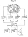
- Fig. 9 shows an NMR imaging apparatus which is an example of the foregoing type of image diagnosis apparatus.
- the NMR imaging apparatus has a magnet section which is configured so that a static magnetic field coil 1 and a gradient magnetic field coil 2 ( made up of coils for the individual x-, y- and z-axes ) are disposed in place.
- the static magnetic field coil 1 is energized by a static magnetic field coil driving section 3 with the gradient magnetic field coil 2 by a gradient magnetic field coil driving section 4, so that in the inside space of the magnet there are created a static magnetic field being uniform in the z-axis direction and gradient magnetic fields oriented in the same direction as that of the static magnetic field but each having a linear gradient in each direction of the x-, y- and z-axes.
- An exciting coil 5 and a detecting coil 6 are disposed in the magnetic field of the magnet section while keeping a rotational angle of 90° therebetween about the z-axis, the former coil being energized by an exciting coil driving section 7 to apply high-frequency electromagnetic wave pulses to a subject (not shown ) placed in the inside space of the magnet with the latter coil detecting an NMR signal coming from a desired spot of the subject and applying it to an analog-to-digital converting section ( hereinafter referred to as A-D converting section ) 8.
- This A-D converting section 8 converts the detection signal into a digital signal and applies it to a control/image processing section 9.
- This control/image processing section 9 is the center of control and image processing over the whole NMR imaging apparatus and is made of a computer.
- the control/image processing section 9 is equipped with an external memory 10.
- the control/image processing section 9 controls the static magnetic field coil driving section 3, gradient magnetic field coil driving section 4, exciting coil driving section 7 and A-D converting section 8 to collect the NMR signal of the subject, and stores the obtained NMR signal ( raw data ) in the external memory 10. Further, the control/image processing section 9 reconstructs an image representative of a subject's section on the basis of the raw data stored in the external memory 10 and stores the reconstructed image in the external memory 10 again. Further, the control/image processing section 9, in accordance with an instruction from an operator which is given through an operator console 15, reads out the reconstructed image from the external memory 10 and applies it through a display control section 11 to a display unit 14 where it is displayed. At this stage, a window level and a window width for image displaying are regulated for the purpose of making the brightness and gradation of the displayed image adequate.
- the value of the pixel data forming the reconstructed image and its range of variation i.e. the brightness and gradation of the reconstructed image
- the system of data collection pulse sequence
- the intensity of each of a plurality of echo signals measured in succession becomes progressively weak
- the brightness and gradation of each reconstructed image based on each echo vary.
- the window level and window width must be regulated similarly. Hitherto, such a regulation operation for the window level and window width was very complicated because it was performed by an operator with respect to each reconstructed image. ( Disclosure of the Invention )
- the present invention is characterized in that a window level/window width calculating means (13) obtains, with respect to each reconstructed image, a window level on the basis of the virtual average value of the pixel data of each image and as a window width, a value having a certain relationship with the value of the window level, and when displaying each reconstructed image,adisplay is made in accordance with the thus obtained window level and window width.
- a window level/window width calculating means (13) obtains, with respect to each reconstructed image, a window level on the basis of the virtual average value of the pixel data of each image and as a window width, a value having a certain relationship with the value of the window level, and when displaying each reconstructed image,adisplay is made in accordance with the thus obtained window level and window width.
- a manual setting section (23) may be used as the window level and window width by a changeover operation when necessary.
- Fig. 1 is a schematic block diagram of an embodiment of the present invention, depicted paying attention to the processing of image data.
- the external memory 10 holds raw data pertaining to a subject which has been collected by the NMR imaging apparatus, X-ray CT apparatus, etc. in accordance with the well-known method.
- the control/image processing section 9 includes a reconstruction processing section 12 and a window level/window width calculating section ( hereinafter referred to as W/L calculating section ) 13.
- the reconstruction processing section 12 processes the raw data stored in the external memory 10 through the known image reconstruction technique such as the two-dimensional inverse Fourier transformation and stores the reconstructed image in an image data area of the same external memory 10.
- the image data thus stored in the external memory 10 is read out by the display control section 11 and displayed on the display unit 14.
- the W/L calculating section 13 obtains, through techniques hereinafter described in greater detail and with respect to each reconstructed image, a window level and a window width used in displaying each image and stores them in the external memory 10 in paired form with the image data of the corresponding reconstructed image.
- the window level and window width can be set manually by a manual setting section 23, other than being obtained by the W/L calculating section 13.
- Either the window level and window width stored in the external memory 10 or those set by the manual setting section 23 are selected by a changeover switch 22 to be applied to the display control section 11.
- the changeover switch 22 is turned by controlling an AUT/ MAN changeover control section 21.
- the display control section 11 is to read out the image data of the external memory 10 and display it on the display unit 14 in the form of an image, a display is made with a window level and a window width which are determined by a window level designating value and a window width designating value given through the changeover switch 22.
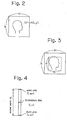
- the W/L calculating section 13 calculates the window level and window width as follows. Let the image data, i.e. the two-dimensional image data, pertaining to some reconstructed image be given in the form of pixel data A(i,j) of N x N matrix as shown in Fig. 2, then, the W/L calculating section 13 obtains the window level L 1 for image displaying using the pixel data A(i,j) in accordance with the following expression (1):
- This expression (1) means that the average value of the pixel data of the reconstructed image is used as the window level.
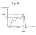
- the W/L calculating section 13 obtains the window width W 1 using the calculated value L 1 of the window level in accordance with the following expression (2):
- the window level L 1 obtained is the average value of all pixel data
- the window width W 1 obtained is 1 to 3 times the value L 1 of the window level.
- a magnification ratio, 1 to 3, for determination of the window width W 1 is determined depending on the type of an object spot of the subject.
- the two-dimensional image data and the window level L 1 and window width W 1 annexed to that data are read out and allied to the display control section 11, so that a display is made with the intermediate value of the brightness of the display image, i.e. the window level, being set to the average value of the pixels and with the difference between the white level and the black level, i.e. the window width, being set to 1 to 3 times the average value of the pixel data.
- Determination of the window level and window width done by the W/L calculating section 13 can be carried out in accordance with, other than the foregoing expressions (1) and (2), several manners as follows. That is,
- the switching between AUT and MAN done by the changeover switch 22 may be made independently between the window level and the window width.
- the calculated value held in the external memory 10 of either the window level or the window width is used as the one, and some value manually set in the manual setting section is used as the other.
Landscapes
- Physics & Mathematics (AREA)
- General Physics & Mathematics (AREA)
- Engineering & Computer Science (AREA)
- Theoretical Computer Science (AREA)
- Signal Processing (AREA)
- General Health & Medical Sciences (AREA)
- Nuclear Medicine, Radiotherapy & Molecular Imaging (AREA)
- Radiology & Medical Imaging (AREA)
- Health & Medical Sciences (AREA)
- High Energy & Nuclear Physics (AREA)
- Condensed Matter Physics & Semiconductors (AREA)
- Image Analysis (AREA)
- Apparatus For Radiation Diagnosis (AREA)
- Image Processing (AREA)
- Analysing Materials By The Use Of Radiation (AREA)
- Magnetic Resonance Imaging Apparatus (AREA)
Abstract
Applications Claiming Priority (3)
| Application Number | Priority Date | Filing Date | Title |
|---|---|---|---|
| JP155853/86 | 1986-07-02 | ||
| JP61155853A JPS6311146A (ja) | 1986-07-02 | 1986-07-02 | 画像診断装置 |
| PCT/JP1987/000462 WO1988000026A1 (fr) | 1986-07-02 | 1987-07-02 | Appareil de diagnostic par l'image |
Publications (3)
| Publication Number | Publication Date |
|---|---|
| EP0312596A1 true EP0312596A1 (fr) | 1989-04-26 |
| EP0312596A4 EP0312596A4 (en) | 1991-03-13 |
| EP0312596B1 EP0312596B1 (fr) | 1994-04-20 |
Family
ID=15614927
Family Applications (1)
| Application Number | Title | Priority Date | Filing Date |
|---|---|---|---|
| EP87904316A Expired - Lifetime EP0312596B1 (fr) | 1986-07-02 | 1987-07-02 | Appareil de diagnostic par l'image |
Country Status (5)
| Country | Link |
|---|---|
| US (1) | US5058176A (fr) |
| EP (1) | EP0312596B1 (fr) |
| JP (1) | JPS6311146A (fr) |
| DE (1) | DE3789667T2 (fr) |
| WO (1) | WO1988000026A1 (fr) |
Cited By (1)
| Publication number | Priority date | Publication date | Assignee | Title |
|---|---|---|---|---|
| EP0409206A3 (en) * | 1989-07-19 | 1992-11-19 | Kabushiki Kaisha Toshiba | Digital image display apparatus |
Families Citing this family (17)
| Publication number | Priority date | Publication date | Assignee | Title |
|---|---|---|---|---|
| FR2636451A1 (fr) * | 1988-09-13 | 1990-03-16 | Gen Electric Cgr | Procede de reconstruction d'arborescence a trois dimensions par etiquetage |
| JPH02260073A (ja) * | 1989-03-31 | 1990-10-22 | Toshiba Corp | 画像表示装置 |
| JPH0616767B2 (ja) * | 1990-02-14 | 1994-03-09 | 株式会社東芝 | 画像表示装置 |
| US5253281A (en) * | 1991-07-30 | 1993-10-12 | Siemens Aktiengesellschaft | X-ray diagnostics installation for subtraction angiography |
| DE69331982T2 (de) * | 1992-11-27 | 2003-01-23 | Fuji Photo Film Co., Ltd. | Verfahren zur Lageanpassung von Röntgenbildern |
| US5447153A (en) * | 1993-07-02 | 1995-09-05 | Eastman Kodak Company | Real-time window/leveling on a radiographic workstation |
| JP3476244B2 (ja) * | 1994-05-13 | 2003-12-10 | ジーイー横河メディカルシステム株式会社 | 投影画像処理方法及び投影画像処理装置 |
| JP2964321B2 (ja) * | 1997-09-01 | 1999-10-18 | ジーイー横河メディカルシステム株式会社 | 画像表示方法、画像表示装置および画像診断装置 |
| JP2004517647A (ja) | 2000-07-14 | 2004-06-17 | ヒル−ロム サービシーズ,インコーポレイティド | 肺治療装置 |
| JP4248221B2 (ja) * | 2002-10-23 | 2009-04-02 | 株式会社キーエンス | 画像処理装置 |
| JP2006325966A (ja) * | 2005-05-26 | 2006-12-07 | Ge Medical Systems Global Technology Co Llc | 撮影装置および、その表示装置 |
| US7869642B2 (en) * | 2006-01-31 | 2011-01-11 | Agfa Inc. | Window leveling system and method |
| JP2009050615A (ja) * | 2007-08-29 | 2009-03-12 | Ge Medical Systems Global Technology Co Llc | 磁気共鳴イメージング装置および磁気共鳴画像表示方法 |
| DE102011003857B4 (de) * | 2011-02-09 | 2016-12-15 | Siemens Healthcare Gmbh | Verfahren zur Anpassung einer Grauwertfensterung, Recheneinheit, Röntgeneinrichtung und Datenträger |
| CN104905808A (zh) * | 2014-03-12 | 2015-09-16 | 上海联影医疗科技有限公司 | 定位片图像的实时显示方法和定位片图像的实时显示系统 |
| CN105678691B (zh) * | 2016-01-07 | 2019-07-12 | 上海箩箕技术有限公司 | 一种图像转换的方法及装置 |
| CN111462115B (zh) * | 2020-04-27 | 2024-06-14 | 上海联影医疗科技股份有限公司 | 医学图像显示方法、装置和计算机设备 |
Family Cites Families (9)
| Publication number | Priority date | Publication date | Assignee | Title |
|---|---|---|---|---|
| JPS6037948B2 (ja) * | 1978-06-14 | 1985-08-29 | 株式会社東芝 | 画像表示装置 |
| JPS6075033A (ja) * | 1983-09-30 | 1985-04-27 | 株式会社東芝 | X線診断装置 |
| JPH0622497B2 (ja) * | 1984-07-24 | 1994-03-30 | 株式会社島津製作所 | 医用画像表示装置 |
| JPS61172541A (ja) * | 1985-01-25 | 1986-08-04 | 株式会社島津製作所 | ダブルウインドウ表示装置 |
| JPS61194576A (ja) * | 1985-02-23 | 1986-08-28 | Toshiba Corp | 画像処理装置 |
| JPS61231476A (ja) * | 1985-04-05 | 1986-10-15 | Toshiba Corp | デ−タ変換装置 |
| FR2581775B1 (fr) * | 1985-05-10 | 1990-03-23 | Thomson Cgr | Procede de reglage de l'echelle des gris dans la reproduction d'images numerisees et systeme mettant en oeuvre ce procede |
| JPS61270788A (ja) * | 1985-05-27 | 1986-12-01 | 株式会社東芝 | 画像処理装置 |
| JP3268021B2 (ja) * | 1992-08-27 | 2002-03-25 | 株式会社ソキア | Gps受信機の作動制御方法 |
-
1986
- 1986-07-02 JP JP61155853A patent/JPS6311146A/ja active Granted
-
1987
- 1987-07-02 WO PCT/JP1987/000462 patent/WO1988000026A1/fr not_active Ceased
- 1987-07-02 EP EP87904316A patent/EP0312596B1/fr not_active Expired - Lifetime
- 1987-07-02 US US07/295,038 patent/US5058176A/en not_active Expired - Fee Related
- 1987-07-02 DE DE3789667T patent/DE3789667T2/de not_active Expired - Fee Related
Cited By (2)
| Publication number | Priority date | Publication date | Assignee | Title |
|---|---|---|---|---|
| EP0409206A3 (en) * | 1989-07-19 | 1992-11-19 | Kabushiki Kaisha Toshiba | Digital image display apparatus |
| US5305204A (en) * | 1989-07-19 | 1994-04-19 | Kabushiki Kaisha Toshiba | Digital image display apparatus with automatic window level and window width adjustment |
Also Published As
| Publication number | Publication date |
|---|---|
| EP0312596A4 (en) | 1991-03-13 |
| JPS6311146A (ja) | 1988-01-18 |
| US5058176A (en) | 1991-10-15 |
| DE3789667T2 (de) | 1994-08-04 |
| JPH0558733B2 (fr) | 1993-08-27 |
| WO1988000026A1 (fr) | 1988-01-14 |
| EP0312596B1 (fr) | 1994-04-20 |
| DE3789667D1 (de) | 1994-05-26 |
Similar Documents
| Publication | Publication Date | Title |
|---|---|---|
| EP0312596A1 (fr) | Appareil de diagnostic par l'image | |
| US5204627A (en) | Adaptive NMR angiographic reprojection method | |
| US4761819A (en) | Adaptive noise reduction filter for reconstructed images | |
| US7570051B2 (en) | MR tomography with a system for contrast optimization of MRT images | |
| EP0096590A1 (fr) | Méthode et appareil de résonance magnétique nucléaire | |
| JP2002345779A (ja) | 核スピントモグラフィ装置およびその作動方法 | |
| US5900732A (en) | Automatic windowing method for MR images | |
| US7145334B2 (en) | Method and magnetic resonance tomography apparatus for producing phase-coded flow images | |
| EP0167350A2 (fr) | Procédé et appareil de résonance magnétique nucléaire | |
| US6157192A (en) | Recovery of signal void arising from field inhomogeneities in echo planar imaging | |
| JPH07222724A (ja) | 画像補正方法 | |
| JPH04364829A (ja) | 磁気共鳴画像処理方法及び装置 | |
| US5785042A (en) | Magnetic resonance imaging method providing for correction of striation artifacts | |
| US7348774B2 (en) | Method and an apparatus for image acquisition and display by means of nuclear magnetic resonance imaging | |
| JPH0759750A (ja) | 核磁気共鳴イメージング装置 | |
| GB2161275A (en) | Nuclear magnetic resonance method and apparatus | |
| US4746865A (en) | Method and system for magnetic resonance imaging | |
| JPH07255693A (ja) | 磁気共鳴診断装置 | |
| EP0246327A1 (fr) | Procede et dispositif d'imagerie nmr | |
| US4870362A (en) | Nuclear magnetic resonance imaging method and apparatus | |
| Wallner et al. | Signal normalization in surface-coil MR imaging. | |
| JPS61234473A (ja) | 画像診断装置 | |
| JP2004057389A (ja) | Mri装置及び画像のww/wl一括設定方法 | |
| JPH06296600A (ja) | 二次元pc法を用いたmrアンギオグラフィー方法及び装置 | |
| JP3731211B2 (ja) | Mri装置 |
Legal Events
| Date | Code | Title | Description |
|---|---|---|---|
| PUAI | Public reference made under article 153(3) epc to a published international application that has entered the european phase |
Free format text: ORIGINAL CODE: 0009012 |
|
| 17P | Request for examination filed |
Effective date: 19890102 |
|
| AK | Designated contracting states |
Kind code of ref document: A1 Designated state(s): DE GB |
|
| A4 | Supplementary search report drawn up and despatched |
Effective date: 19910122 |
|
| AK | Designated contracting states |
Kind code of ref document: A4 Designated state(s): DE GB |
|
| 17Q | First examination report despatched |
Effective date: 19920923 |
|
| GRAA | (expected) grant |
Free format text: ORIGINAL CODE: 0009210 |
|
| AK | Designated contracting states |
Kind code of ref document: B1 Designated state(s): DE GB |
|
| REF | Corresponds to: |
Ref document number: 3789667 Country of ref document: DE Date of ref document: 19940526 |
|
| PLBE | No opposition filed within time limit |
Free format text: ORIGINAL CODE: 0009261 |
|
| STAA | Information on the status of an ep patent application or granted ep patent |
Free format text: STATUS: NO OPPOSITION FILED WITHIN TIME LIMIT |
|
| 26N | No opposition filed | ||
| PGFP | Annual fee paid to national office [announced via postgrant information from national office to epo] |
Ref country code: DE Payment date: 19970624 Year of fee payment: 11 |
|
| PGFP | Annual fee paid to national office [announced via postgrant information from national office to epo] |
Ref country code: GB Payment date: 19970626 Year of fee payment: 11 |
|
| PG25 | Lapsed in a contracting state [announced via postgrant information from national office to epo] |
Ref country code: GB Free format text: LAPSE BECAUSE OF NON-PAYMENT OF DUE FEES Effective date: 19980702 |
|
| GBPC | Gb: european patent ceased through non-payment of renewal fee |
Effective date: 19980702 |
|
| PG25 | Lapsed in a contracting state [announced via postgrant information from national office to epo] |
Ref country code: DE Free format text: LAPSE BECAUSE OF NON-PAYMENT OF DUE FEES Effective date: 19990501 |