EP0312683A2 - Jouet muni d'un mécanisme d'accouplement - Google Patents
Jouet muni d'un mécanisme d'accouplement Download PDFInfo
- Publication number
- EP0312683A2 EP0312683A2 EP88105749A EP88105749A EP0312683A2 EP 0312683 A2 EP0312683 A2 EP 0312683A2 EP 88105749 A EP88105749 A EP 88105749A EP 88105749 A EP88105749 A EP 88105749A EP 0312683 A2 EP0312683 A2 EP 0312683A2
- Authority
- EP
- European Patent Office
- Prior art keywords
- toy
- support
- magnet
- spindle
- aperture
- Prior art date
- Legal status (The legal status is an assumption and is not a legal conclusion. Google has not performed a legal analysis and makes no representation as to the accuracy of the status listed.)
- Withdrawn
Links
- 230000008878 coupling Effects 0.000 title claims abstract description 42
- 238000010168 coupling process Methods 0.000 title claims abstract description 42
- 238000005859 coupling reaction Methods 0.000 title claims abstract description 42
- 230000007246 mechanism Effects 0.000 title claims abstract description 32
- 229920003002 synthetic resin Polymers 0.000 claims description 4
- 239000000057 synthetic resin Substances 0.000 claims description 4
- BGPVFRJUHWVFKM-UHFFFAOYSA-N N1=C2C=CC=CC2=[N+]([O-])C1(CC1)CCC21N=C1C=CC=CC1=[N+]2[O-] Chemical class N1=C2C=CC=CC2=[N+]([O-])C1(CC1)CCC21N=C1C=CC=CC1=[N+]2[O-] BGPVFRJUHWVFKM-UHFFFAOYSA-N 0.000 description 5
- 238000000926 separation method Methods 0.000 description 5
- 238000010586 diagram Methods 0.000 description 3
- 230000000694 effects Effects 0.000 description 1
- 230000005611 electricity Effects 0.000 description 1
- 238000003780 insertion Methods 0.000 description 1
- 230000037431 insertion Effects 0.000 description 1
Images




Classifications
-
- A—HUMAN NECESSITIES
- A63—SPORTS; GAMES; AMUSEMENTS
- A63H—TOYS, e.g. TOPS, DOLLS, HOOPS OR BUILDING BLOCKS
- A63H19/00—Model railways
- A63H19/16—Parts for model railway vehicles
- A63H19/18—Car coupling or uncoupling mechanisms
-
- A—HUMAN NECESSITIES
- A63—SPORTS; GAMES; AMUSEMENTS
- A63H—TOYS, e.g. TOPS, DOLLS, HOOPS OR BUILDING BLOCKS
- A63H17/00—Toy vehicles, e.g. with self-drive; ; Cranes, winches or the like; Accessories therefor
- A63H17/26—Details; Accessories
- A63H17/264—Coupling mechanisms
-
- H—ELECTRICITY
- H01—ELECTRIC ELEMENTS
- H01F—MAGNETS; INDUCTANCES; TRANSFORMERS; SELECTION OF MATERIALS FOR THEIR MAGNETIC PROPERTIES
- H01F7/00—Magnets
- H01F7/02—Permanent magnets [PM]
- H01F7/0231—Magnetic circuits with PM for power or force generation
- H01F7/0252—PM holding devices
- H01F7/0263—Closures, bags, bands, engagement devices with male and female parts
Definitions
- the present invention concerns a toy comprising a coupling mechanism which is used to couple and separate toys with one another, for example, toy vehicles which run.
- Coupling mechanisms for toys in prior art consists of a hook section provided with a hook at one end, and a loop section provided with a loop at one end. The other ends of the hook section and the loop section are attached respectively to either end of the bodies to be connected of the toy. Coupling the bodies to be connected so as to be mutually connectable and disconnetable is effected by linking the hook of the hook section with the loop of the loop section. If the hook of the hook section is undone from the loop of the loop section, the bodies to be connected can be mutually separated.
- the above toy coupling mechanism in prior art involves mutual mechanical coupling and uncoupling of the bodies to be connected by means of engaging and disengaging the tiny hook of the hook section and the loop of the loop section, an operation which is awkward and troublesome.
- the hook of the hook section is usually simply engaged with the loop of the loop section by lowering it downward onto it so that during play, if the bodies that are connected are for example vehicles, there is the problem that any relative vertical movement between them will cause the hook to disengage from the loop and the attached vehicles to separate etc.
- the purpose of the present invention is to offer a toy comprising a coupling mechanism to enable easy coupling and uncoupling of the toy bodies to be attached, and which moreover ensures a connection between them.
- the present toy is characterized in that it makes use of a magnet arrangement and has a support, one end of which is attached to the body to be coupled in such a way as to be able to turn, the other end of the support supporting a magnet in such a way as to allow it to rotate, the magnetic poles of said magnet varying with respect to the direction of rotation.
- the present coupling mechanism is arranged so that when two magnets approach one another, each supported so as to be able to turn on a support and its poles varying with respect to the direction of rotation, the magnets freely rotate to a point where opposite poles on the two magnets face one another, the magnets thus adhering to each other by magnetic force and holding together the two objects to be coupled. Separation of the coupled objects can be achieved by pulling the two magnetic bodies apart with a force greater than that of the magnetic force.
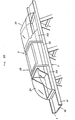
- Figures 1 to 10 show a first practical embodiment of the toy with a toy coupling mechanism according to the present invention.
- 1 is the track, this track 1 consisting of a horizontal runner section 10 and guide 11 provided on both sides of the horizontal runner section 10.
- This vehicle 2 designates a vehicle, the width of this vehicle 2 being approximately equal to or slightly less than that of track 1, it being able to run on track 1 without derailing.
- This vehicle 2 is made up of three carriages, the front and rear carriages 20 being covered by a transparent cover and intended to represent a carriage for passengers or a driver's cab etc., the interior being visible.
- the middle carriage 22 has a transparent roof, and represents the engine car, as shown in Figures 1 and 11.
- This vehicle is fitted with drive wheels and free-turning wheels 24 which all turn, and a drive motor (not shown in the diagram) is built into the engine car 22 of the vehicle 2, this drive motor M engaging with the drive wheels 24, said drive motor being connected to the mains supply (not shown).
- a gap 25 is provided between the front and rear passenger carriage, driver cab sections 20 and the front and rear ends of the engine car 22 of this vehicle 2, and a vertical pillar-shaped spindle 26 is provided in these gaps 25.
- numeral 3 designates the support of the toy coupling mechanism in this device.
- This support 3 is made of synthetic resin or the like, and has a round aperture 31 provided in a tongued end 30 (see Figure 2).
- the inside diameter of this aperture 31 is slightly larger than the outside diameter of said spindle 26 of the vehicle 2.
- fork-shaped support arms 32 at the other end of this support 3 are fork-shaped support arms 32, protuberances 33 being integrally formed on the inner surfaces of these support arms 32 as they face each other.
- the other end 30 of the support 3 is designed so that it can turn around said spindle 26 of the vehicle 2 by means of the aperture 30, and can moreover move upwards and downwards.
- the support 3 is attached to the vehicle 2 by separating the upper parts having the cover 21 of the roof section 23 from the lower parts and the wheels and fitting the spindle 26 to the upper part or the lower part, or the upper part and the lower part, sliding the support 3 around the spindle 26, and then fitting the upper part back together with the lower part.
- FIG. 1 to 9,4 designates the magnet of the toy coupling mechanism in this device.
- This magnet 4 is of cylindrical shape, and has an aperture 40 along its central axis ( Figure 3).
- the N and S poles of this magnet 4 are arranged around the axis, i.e. in the direction of rotation.
- the half of the magnet 4 on one side of the axis is the north pole, and the other half is the south pole.
- This magnet 4 is placed between the support arms 32 of said support 3, the protuberances 33 of the support arms 32 fitting into the aperture 40 of the magnet 4, allowing it to rotate in the support 3 at right angles to the axis of the spindle 26.
- the toy coupling mechanism of the present device in this practical embodiment is constituted as explained above with the magnets 4 supported in the support 3 in such a way that they can rotate, and with N and S poles which vary according to the direction of rotation, when the magnets 4 and 4 of two carriages 20, 22 approach each other and when the facing parts of the two magnets 4 and 4 are of the same pole, the two magnets 4 and 4 can rotate freely to a point where the facing parts are of different poles, and are attracted together by magnetic force. As a result the two carriages 20 and 22 are coupled very simply. The three-sections of the vehicles 2 are coupled in the same way.
- the toy coupling mechanism of the present device couples together two carriages 20 and 22 using the magnetic force of the two magnets 4 and 4, the two carriages 20 and 22 will not separate unless forced apart with a strength greater than that of the two magnets 4 and 4.
- a secure coupling is obtained and there is no danger of the two carriages 20 and 22 coming apart due to the coupling mechanisms disengaging.
- Figures 11 to 19 show a second practical embodiment of the toy coupling mechanism according to this invention.
- FIG. 5 designates a primary support, this primary support being made of synthetic resin or the like and having a tongued end 50 in which there is a round aperture 51 (Figures 11 and 12).
- the inside diameter of this aperture 51 is slightly larger than the outside diameter of the spindle 26 of the said vehicle 2.
- an insert 52 on the front face of which is integrally formed a protuberance 53, ridges 54 being integrally formed on the upper and lower faces of the insert 52.
- the upper and lower faces of these ridges 54 are formed with a tapered slope from front to rear.
- Figures 14 to 19 6 designates a secondary embodiment of a support, and is also formed of synthetic resin or the like.
- This secondary support 6 has a cavity formed in the shape of a rectangular parallel pipe, and has stops 60 on the upper and lower parts of an opening at one end, and accommodating slots 61 on the upper and lower surfaces at the other end which engage with the ridges 54 on the said primary supporter 5. There are protrusions at the front edge of these slots 61 which project slightly inwards and are designed to abut against the front surfaces of the ridges 54 on the primary support 5.
- said second embodiment of the invention 7 designates a magnet which is in cylindrical shape, and the outside diameter of this magnet 7 is slightly less than the height of the space within the said secondary support 6.
- the N and S poles of this magnet 7 vary with respect to the direction of rotation, in other words around the central axis.
- the said magnet 7 is inserted into the cavity of the secondary support 6, and then with insertion of the insert 52 of the primary support 5 into the cavity of the secondary support 6 the ridges 54 on the primary support 5 engage with the slots 61 in the secondary support 6.
- the magnet 7, pressed by the protuberance 53 of the primary support 5 projects from the stops 60 of the secondary support 6, and is thus supported by the primary support 5 and the secondary support 6 in such a way as to be able to rotate around its central axis.
- the other end 50 of the primary support 5 is attached to the spindles 26 of the carriages 20, 22 by means of the aperture 51 in such a way that it can turn. This means of attachment is the same as for that in the first practical embodiment described above.
- the toy coupling mechanism of this device in this practical embodiment achives the same effect as the first practical embodiment described above.
- the supports 3, 5 and 6 are attached to the carriages 20 and 22 in such a way that they can turn, but they may also be attached to the carriages using a ball and socket joint.
- magnets 4 and 7 in the above practical embodiments are of cylindrical shape, they may be of polyhedral, spherical or other shape providing they can be supported by supports 3, 5 and 6 in such a way that they can rotate.
- the toy coupling mechanism of the present device is arranged to support magnets whose poles vary with the direction of rotation, in other words around their axis of rotation, and in such a way that they can rotate.
- magnets whose poles vary with the direction of rotation, in other words around their axis of rotation, and in such a way that they can rotate.
Landscapes
- Physics & Mathematics (AREA)
- Electromagnetism (AREA)
- Engineering & Computer Science (AREA)
- Power Engineering (AREA)
- Toys (AREA)
Applications Claiming Priority (2)
| Application Number | Priority Date | Filing Date | Title |
|---|---|---|---|
| JP1987159960U JPH0433915Y2 (fr) | 1987-10-21 | 1987-10-21 | |
| JP159960/87U | 1987-10-21 |
Publications (2)
| Publication Number | Publication Date |
|---|---|
| EP0312683A2 true EP0312683A2 (fr) | 1989-04-26 |
| EP0312683A3 EP0312683A3 (en) | 1990-12-05 |
Family
ID=15704931
Family Applications (1)
| Application Number | Title | Priority Date | Filing Date |
|---|---|---|---|
| EP19880105749 Withdrawn EP0312683A3 (en) | 1987-10-21 | 1988-04-11 | Toy comprising a coupling mechanism |
Country Status (3)
| Country | Link |
|---|---|
| US (1) | US5048704A (fr) |
| EP (1) | EP0312683A3 (fr) |
| JP (1) | JPH0433915Y2 (fr) |
Cited By (4)
| Publication number | Priority date | Publication date | Assignee | Title |
|---|---|---|---|---|
| EP1260254A3 (fr) * | 2001-05-21 | 2003-08-20 | Learning Curve International, Inc. | Dispositif d'accouplement magnétique pour véhicule jouet |
| EP1509298A4 (fr) * | 2002-05-30 | 2006-10-25 | Mattel Inc | Vehicules-jouets a attelage magnetique |
| CN103093920A (zh) * | 2011-11-03 | 2013-05-08 | 闪烁天空国际有限公司 | 磁性连接器装置及相关系统和方法 |
| CN104008687A (zh) * | 2014-05-20 | 2014-08-27 | 东莞市中科教育电子有限公司 | 一种基于红外光电技术的电子积木及其电路 |
Families Citing this family (21)
| Publication number | Priority date | Publication date | Assignee | Title |
|---|---|---|---|---|
| SE9600265L (sv) * | 1996-01-25 | 1997-07-26 | Brio Ab | Magnetkopplingsanordning på ett leksaksfordon |
| US6012396A (en) * | 1998-03-12 | 2000-01-11 | Schulz; Bruce Deleon | Electric rail transportation system, vehicle, and rail used in the transportation system |
| SE514023C2 (sv) * | 1999-12-21 | 2000-12-11 | Brio Ab | Magnetkopplingsanordning på ett leksaksfordon |
| US6379213B2 (en) * | 2000-02-28 | 2002-04-30 | Michael W. Whitworth | Inverted pivot |
| FR2841149B3 (fr) * | 2002-05-30 | 2004-07-30 | Mattel Inc | Vehicules jouets composites |
| EP2189202A1 (fr) * | 2003-01-14 | 2010-05-26 | Orda Korea Co., Ltd | Appareil de jointoiement doté d'un aimant rotatif intégré et jouet de type construction doté de celui-ci |
| US7080745B2 (en) * | 2004-03-10 | 2006-07-25 | Senften David A | Magnetic coupling and uncoupling system for model railroad rolling stock |
| WO2005098791A2 (fr) * | 2004-03-28 | 2005-10-20 | Milwaukee School Of Engineering | Modeles moleculaires |
| US7154363B2 (en) * | 2004-12-23 | 2006-12-26 | Larry Dean Hunts | Magnetic connector apparatus |
| US7469782B2 (en) * | 2005-07-22 | 2008-12-30 | Dew Engineering And Development Limited | Conveyor system for loading and unloading aircraft baggage |
| US20080110845A1 (en) * | 2006-11-13 | 2008-05-15 | Kadee Quality Products, Inc. | Magnetic core actuator |
| US8464881B2 (en) * | 2011-06-27 | 2013-06-18 | Gerhard Rieskamp | Coupling device for a cart, and rail-guided cart with a coupling device |
| DE102011051361A1 (de) * | 2011-06-27 | 2012-12-27 | Gerimo GmbH | Kupplungsvorrichtung für einen Wagen und schienengeführter Wagen mit der Kupplungsvorrichtung |
| US20130111710A1 (en) * | 2011-11-03 | 2013-05-09 | Sparkling Sky International Limited | Multi-pole magnetic connector apparatus |
| US9643100B2 (en) | 2012-12-21 | 2017-05-09 | Guidecraft, Inc. | Magnetic toy apparatuses and methods |
| TWI595347B (zh) * | 2015-01-05 | 2017-08-11 | 仁寶電腦工業股份有限公司 | 對位結構 |
| US9956493B1 (en) | 2017-05-12 | 2018-05-01 | Sparkling Sky International Limited | Slide construction assemblies |
| IT201900001229A1 (it) * | 2019-01-28 | 2020-07-28 | Plastwood Italia S R L | Assieme magnetico |
| US11471783B2 (en) | 2019-04-16 | 2022-10-18 | Mattel, Inc. | Toy vehicle track system |
| AU2020100835A4 (en) * | 2020-05-25 | 2020-07-02 | Icon23 Pty Ltd | A toy vehicle assembly |
| US20240128682A1 (en) * | 2022-10-13 | 2024-04-18 | Michael Sansur | Magnetically Coupled Circuits |
Family Cites Families (13)
| Publication number | Priority date | Publication date | Assignee | Title |
|---|---|---|---|---|
| US2500180A (en) * | 1945-09-21 | 1950-03-14 | Hubbell Harvey | Coupling for toy trains |
| GB642829A (en) * | 1947-09-03 | 1950-09-13 | Arthur Gueydan | Improvements in or relating to mechanical toys |
| US2607157A (en) * | 1948-08-25 | 1952-08-19 | Toy Craft Corp | Magnetically coupled toy train |
| US2939245A (en) * | 1958-03-31 | 1960-06-07 | Orel Ben | Magnetically coupled toys |
| US3330066A (en) * | 1964-02-27 | 1967-07-11 | Fisher Price Toys Inc | Magnetic connector for wheeled toys |
| US3303606A (en) * | 1964-05-05 | 1967-02-14 | Mann Morley | Magnetic toy vehicle set |
| DE1478459A1 (de) * | 1964-10-23 | 1969-06-19 | Harald Heinicke | Kupplung fuer Spielzeug- und Modelleisenbahnfahrzeuge mit magnetischer Entkuppelungsvorrichtung |
| DE1478460A1 (de) * | 1964-11-10 | 1969-06-19 | Harald Heinicke | Kupplung mit Drehgelenk |
| US3605332A (en) * | 1970-01-16 | 1971-09-20 | Atlas Tool Co Inc | Draft gear arrangement for miniature railway rolling stock |
| DE2219684C3 (de) * | 1972-04-21 | 1980-05-08 | Knorr-Bremse, 1000 Berlin Und 8000 Muenchen | Rohrleitungskupplung für eine Mittelpufferkupplung von Schienenfahrzeugen |
| SE392570B (sv) * | 1973-01-26 | 1977-04-04 | Brio Scanditoy Ab | Magnetisk koppling for leksaksfordon |
| DE2442633C2 (de) * | 1974-09-06 | 1984-01-26 | Interlego A/S, 7190 Billund | Kupplung für Spielzeug- und Modelleisenbahnfahrzeuge |
| DE3339521A1 (de) * | 1983-11-02 | 1985-05-09 | Hermann Rossberg KG, 8496 Lam | Magnetkupplung fuer spielfahrzeuge |
-
1987
- 1987-10-21 JP JP1987159960U patent/JPH0433915Y2/ja not_active Expired
-
1988
- 1988-04-11 EP EP19880105749 patent/EP0312683A3/en not_active Withdrawn
- 1988-10-20 US US07/260,464 patent/US5048704A/en not_active Expired - Fee Related
Cited By (6)
| Publication number | Priority date | Publication date | Assignee | Title |
|---|---|---|---|---|
| US6722941B2 (en) | 1999-02-12 | 2004-04-20 | Learning Curve International Inc. | Toy vehicle magnetic coupler |
| EP1260254A3 (fr) * | 2001-05-21 | 2003-08-20 | Learning Curve International, Inc. | Dispositif d'accouplement magnétique pour véhicule jouet |
| EP1509298A4 (fr) * | 2002-05-30 | 2006-10-25 | Mattel Inc | Vehicules-jouets a attelage magnetique |
| CN103093920A (zh) * | 2011-11-03 | 2013-05-08 | 闪烁天空国际有限公司 | 磁性连接器装置及相关系统和方法 |
| CN103093920B (zh) * | 2011-11-03 | 2015-07-22 | 闪烁天空国际有限公司 | 磁性连接器装置及相关系统和方法 |
| CN104008687A (zh) * | 2014-05-20 | 2014-08-27 | 东莞市中科教育电子有限公司 | 一种基于红外光电技术的电子积木及其电路 |
Also Published As
| Publication number | Publication date |
|---|---|
| JPH0433915Y2 (fr) | 1992-08-13 |
| EP0312683A3 (en) | 1990-12-05 |
| US5048704A (en) | 1991-09-17 |
| JPH0165096U (fr) | 1989-04-26 |
Similar Documents
| Publication | Publication Date | Title |
|---|---|---|
| EP0312683A2 (fr) | Jouet muni d'un mécanisme d'accouplement | |
| KR970000430B1 (ko) | 톱니형 철도 완구 | |
| EP0388746B1 (fr) | Système d'accouplement pour un article modulaire | |
| EP0728506A1 (fr) | Jeu de construction | |
| US3330066A (en) | Magnetic connector for wheeled toys | |
| US20170128847A1 (en) | Action character models and accessories with movable parts | |
| CN201500454U (zh) | 可实现漂移的玩具遥控车 | |
| US6896574B2 (en) | Magnetically coupled toy vehicles | |
| US20190209937A1 (en) | Action character models and accessories with movable parts | |
| EP1260254A2 (fr) | Dispositif d'accouplement magnétique pour véhicule jouet | |
| JP7195505B2 (ja) | 磁着性を有するブロック玩具および走行コースの設計図 | |
| US20080248716A1 (en) | Toy track system | |
| US20020177384A1 (en) | Magnetically coupled toy | |
| JPS5814231B2 (ja) | 玩具及び模型鉄道車輌用連結器 | |
| GB2206499A (en) | Track-running toy vehicle system | |
| CN208990224U (zh) | 一种积木滑板拼接玩具 | |
| JP3031141U (ja) | 文字表示付玩具列車 | |
| JP2008086750A (ja) | 車両玩具の車輪装置及び車両玩具 | |
| JPS62197108U (fr) | ||
| JP2679951B2 (ja) | 解体玩具 | |
| ES2040026T3 (es) | Dispositivo de acoplamiento (enganche) para unir vehiculos de juguete. | |
| CN100534564C (zh) | 教育性的揿扣在一起的玩具车辆系统 | |
| JPH0450839B2 (fr) | ||
| JP2001070663A (ja) | 玩具における連結構造 | |
| CN208130489U (zh) | 一种积木式机器人玩具 |
Legal Events
| Date | Code | Title | Description |
|---|---|---|---|
| PUAI | Public reference made under article 153(3) epc to a published international application that has entered the european phase |
Free format text: ORIGINAL CODE: 0009012 |
|
| AK | Designated contracting states |
Kind code of ref document: A2 Designated state(s): AT BE CH DE FR IT LI NL |
|
| PUAL | Search report despatched |
Free format text: ORIGINAL CODE: 0009013 |
|
| AK | Designated contracting states |
Kind code of ref document: A3 Designated state(s): AT BE CH DE FR IT LI NL |
|
| STAA | Information on the status of an ep patent application or granted ep patent |
Free format text: STATUS: THE APPLICATION IS DEEMED TO BE WITHDRAWN |
|
| 18D | Application deemed to be withdrawn |
Effective date: 19910606 |