EP0312689A1 - Chaudière - Google Patents
Chaudière Download PDFInfo
- Publication number
- EP0312689A1 EP0312689A1 EP88108446A EP88108446A EP0312689A1 EP 0312689 A1 EP0312689 A1 EP 0312689A1 EP 88108446 A EP88108446 A EP 88108446A EP 88108446 A EP88108446 A EP 88108446A EP 0312689 A1 EP0312689 A1 EP 0312689A1
- Authority
- EP
- European Patent Office
- Prior art keywords
- shell
- boiler
- shells
- pockets
- side shell
- Prior art date
- Legal status (The legal status is an assumption and is not a legal conclusion. Google has not performed a legal analysis and makes no representation as to the accuracy of the status listed.)
- Ceased
Links
- 239000007789 gas Substances 0.000 claims abstract description 29
- 238000002485 combustion reaction Methods 0.000 claims abstract description 18
- 238000010438 heat treatment Methods 0.000 claims abstract description 16
- XLYOFNOQVPJJNP-UHFFFAOYSA-N water Substances O XLYOFNOQVPJJNP-UHFFFAOYSA-N 0.000 claims abstract 2
- 239000003546 flue gas Substances 0.000 claims description 7
- UGFAIRIUMAVXCW-UHFFFAOYSA-N Carbon monoxide Chemical compound [O+]#[C-] UGFAIRIUMAVXCW-UHFFFAOYSA-N 0.000 claims description 6
- 238000004519 manufacturing process Methods 0.000 abstract description 5
- 230000037431 insertion Effects 0.000 abstract 1
- 238000003780 insertion Methods 0.000 abstract 1
- 239000000779 smoke Substances 0.000 abstract 1
- 239000002912 waste gas Substances 0.000 abstract 1
- 238000013461 design Methods 0.000 description 6
- 238000009833 condensation Methods 0.000 description 2
- 230000005494 condensation Effects 0.000 description 2
- 238000010276 construction Methods 0.000 description 2
- 238000009434 installation Methods 0.000 description 2
- 238000004080 punching Methods 0.000 description 2
- 238000007493 shaping process Methods 0.000 description 2
- 230000004308 accommodation Effects 0.000 description 1
- 238000011161 development Methods 0.000 description 1
- 230000018109 developmental process Effects 0.000 description 1
- 238000000605 extraction Methods 0.000 description 1
- 239000000446 fuel Substances 0.000 description 1
- 206010022000 influenza Diseases 0.000 description 1
- 230000010354 integration Effects 0.000 description 1
- 238000000034 method Methods 0.000 description 1
- 238000003825 pressing Methods 0.000 description 1
- 238000012549 training Methods 0.000 description 1
- 238000012546 transfer Methods 0.000 description 1
- 230000007704 transition Effects 0.000 description 1
Images

Classifications
-
- F—MECHANICAL ENGINEERING; LIGHTING; HEATING; WEAPONS; BLASTING
- F24—HEATING; RANGES; VENTILATING
- F24H—FLUID HEATERS, e.g. WATER OR AIR HEATERS, HAVING HEAT-GENERATING MEANS, e.g. HEAT PUMPS, IN GENERAL
- F24H8/00—Fluid heaters characterised by means for extracting latent heat from flue gases by means of condensation
-
- F—MECHANICAL ENGINEERING; LIGHTING; HEATING; WEAPONS; BLASTING
- F24—HEATING; RANGES; VENTILATING
- F24H—FLUID HEATERS, e.g. WATER OR AIR HEATERS, HAVING HEAT-GENERATING MEANS, e.g. HEAT PUMPS, IN GENERAL
- F24H1/00—Water heaters, e.g. boilers, continuous-flow heaters or water-storage heaters
- F24H1/22—Water heaters other than continuous-flow or water-storage heaters, e.g. water heaters for central heating
- F24H1/24—Water heaters other than continuous-flow or water-storage heaters, e.g. water heaters for central heating with water mantle surrounding the combustion chamber or chambers
- F24H1/26—Water heaters other than continuous-flow or water-storage heaters, e.g. water heaters for central heating with water mantle surrounding the combustion chamber or chambers the water mantle forming an integral body
- F24H1/28—Water heaters other than continuous-flow or water-storage heaters, e.g. water heaters for central heating with water mantle surrounding the combustion chamber or chambers the water mantle forming an integral body including one or more furnace or fire tubes
- F24H1/287—Water heaters other than continuous-flow or water-storage heaters, e.g. water heaters for central heating with water mantle surrounding the combustion chamber or chambers the water mantle forming an integral body including one or more furnace or fire tubes with the fire tubes arranged in line with the combustion chamber
-
- F—MECHANICAL ENGINEERING; LIGHTING; HEATING; WEAPONS; BLASTING
- F24—HEATING; RANGES; VENTILATING
- F24H—FLUID HEATERS, e.g. WATER OR AIR HEATERS, HAVING HEAT-GENERATING MEANS, e.g. HEAT PUMPS, IN GENERAL
- F24H6/00—Combined water and air heaters
-
- Y—GENERAL TAGGING OF NEW TECHNOLOGICAL DEVELOPMENTS; GENERAL TAGGING OF CROSS-SECTIONAL TECHNOLOGIES SPANNING OVER SEVERAL SECTIONS OF THE IPC; TECHNICAL SUBJECTS COVERED BY FORMER USPC CROSS-REFERENCE ART COLLECTIONS [XRACs] AND DIGESTS
- Y02—TECHNOLOGIES OR APPLICATIONS FOR MITIGATION OR ADAPTATION AGAINST CLIMATE CHANGE
- Y02B—CLIMATE CHANGE MITIGATION TECHNOLOGIES RELATED TO BUILDINGS, e.g. HOUSING, HOUSE APPLIANCES OR RELATED END-USER APPLICATIONS
- Y02B30/00—Energy efficient heating, ventilation or air conditioning [HVAC]
Definitions
- the invention relates to a boiler, in particular for the combustion of gaseous fuels, which is designed according to the preamble of the main claim.
- Such boilers in which the exhausting heating or flue gases flow without a reversal deflection to the flue gas outlet under the passage of heating gas pockets, are known, for example, according to DE-U-82 19 423.
- the manufacture of such boilers is considered to be expensive in that the bottom of the combustion chamber and also the rear wall of the water-carrying housing must be provided with corresponding slots for the pocket integration, and the pockets are only integrated directly in conjunction with the housing rear wall or the entire water-conducting housing can be.
- the combustion chamber base to be provided with slots inevitably has a different shape than the rear wall of the housing, which is also to be provided with slots, so that different stamping tools must be used for these parts.
- the invention is therefore based on the object to improve a boiler of the type mentioned in such a way that in particular the tooling and assembly costs can be reduced or simplified, with the proviso, despite the pocket-shaped design of the heating gas flues, all the heating gas-carrying parts after prior assembly as in to be able to insert a closed unit in the boiler housing.
- This inventive design of the boiler makes it practical and advantageous to use only one shaping and punching tool for the production of both the combustion chamber base and the other shells involved, and furthermore all parts of the boiler which are involved in the flame or heating gas flow can be used , despite the pocket design, can be easily assembled before installation in the boiler housing and then installed as a unit in the boiler housing. Furthermore, practically the same shaping and punching tool can be used for the front and rear walls of the water-carrying housing, since these are to be provided with the same through openings for the installation of the aforementioned unit. In addition, there are no further manufacturing processes on the housing for the purpose of attaching a collection chamber provided with an exhaust opening behind the hot gas draw pockets, since the collection chamber is already part of the unit to be installed overall in the boiler housing.
- the construction principle according to the invention can also be maintained and further used if an air / exhaust gas heat exchanger is to be connected downstream of the heating gas pockets for reasons of maintaining condensate operation in times of high heat demand.
- this downstream heat exchanger is easy to integrate between the shells that otherwise form the collecting chamber, which will be explained in more detail.
- this air / exhaust gas heat exchanger can be manufactured using the same tools for the production of the shells.
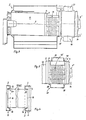
- the heating boiler consists in a known manner of a water-carrying housing I, in which a substantially horizontally extending combustion chamber 11 is arranged, from the rear bottom of which several heating gas pockets 13 lead to a flue gas collecting chamber 1 with an exhaust gas outlet connection.
- the flue gas collecting chamber 1 is formed from two press-formed shells 3, 4 which are identical with respect to their opposing connecting webs 2 and their depth T. is formed from the shell press-formed trigger connector 5 '. As shown, this shell can easily with the pressing process and also a bulge deformation be conveyed as a transition to the discharge nozzle 5 '.
- Pocket insert slots 8 are arranged on the shell-side shell, closing a cross-section-corresponding opening 6 in the rear wall 7 of the shell, and a shell 9, identical to the shell-side shell 3, forms the bottom of the combustion chamber 11 molded wall part 11 'of the combustion chamber 11 and welded to it in a gastight and liquid-tight manner.
- the heating gas draw pockets 13 which are inserted into the pocket insert slots 8 with their ends.
- the heating gas draw pockets 13 in the slots 8 they are provided with circumferential flanged edges 12 pointing in the same direction as the connecting webs 2 (see FIG. 4).
- the end edges 19 of the heating gas pockets 13 are pushed into the slots 8 up to the ends 20 of the flanged edges 12 in the shells and the end edges of the pockets 13 and the flanged edges 12 are tightly connected to one another.
- These edges are completely open and can be welded without any problems, that is to say the heating gas pockets 13 are first plugged and welded together with the shells 3 and 9 involved, for example in an arrangement according to FIG. 2, after which the entire structure is connected to the connecting web 2 of the shell 9 attached to the combustion chamber wall 11 'and then the whole structure is closed with the shell 4.
- This whole unit is either from the rear wall 7 or from the front wall 7 'of the housing I inserted into the housing and firmly connected to it along the opening edges.
- the air heat exchanger 15 is also advantageously off two to the boiler-side shell 3 identical shells 3 ', 4' formed, and these are connected with their connecting webs 2 on the one hand to the boiler-side and on the other hand to the discharge-side shell 3, 4. Extending between the shells 3 ', 4' then exactly as in the above-described actual extraction area of the boiler flue gas passage pockets 13 ', the heat exchange surface of which corresponds at least to that of the heating gas flow pockets 13.
- a connection to the connecting webs 2 of the shells 3', 4 ' is provided with the pocket area and provided with air inlet and outlet connections 16, 17 Enclosure wall 18 arranged.
- boiler-side shell 3 and the trigger-side shell 4 are dimensioned larger in cross section than the bil the combustion chamber floor Ending shell 9, the shell-side shell 3 having identical slots 8 with respect to the shell 9 forming the combustion chamber bottom, which are arranged overall either centrally in relation to the shell center M or eccentrically offset upwards or downwards.
Landscapes
- Engineering & Computer Science (AREA)
- Physics & Mathematics (AREA)
- Thermal Sciences (AREA)
- Chemical & Material Sciences (AREA)
- Combustion & Propulsion (AREA)
- Mechanical Engineering (AREA)
- General Engineering & Computer Science (AREA)
- Housings, Intake/Discharge, And Installation Of Fluid Heaters (AREA)
Applications Claiming Priority (2)
| Application Number | Priority Date | Filing Date | Title |
|---|---|---|---|
| DE3735321 | 1987-10-19 | ||
| DE3735321A DE3735321C1 (de) | 1987-10-19 | 1987-10-19 | Heizkessel |
Publications (1)
| Publication Number | Publication Date |
|---|---|
| EP0312689A1 true EP0312689A1 (fr) | 1989-04-26 |
Family
ID=6338626
Family Applications (1)
| Application Number | Title | Priority Date | Filing Date |
|---|---|---|---|
| EP88108446A Ceased EP0312689A1 (fr) | 1987-10-19 | 1988-05-27 | Chaudière |
Country Status (2)
| Country | Link |
|---|---|
| EP (1) | EP0312689A1 (fr) |
| DE (1) | DE3735321C1 (fr) |
Citations (5)
| Publication number | Priority date | Publication date | Assignee | Title |
|---|---|---|---|---|
| FR427387A (fr) * | 1910-09-02 | 1911-08-02 | Calorie Compagnie Suisse De Chauffage Et De Ventil | Chaudière pour le chauffage des habitations |
| BE651186A (fr) * | 1963-08-02 | 1964-11-16 | ||
| DE8219423U1 (de) * | 1982-07-07 | 1982-10-07 | Buderus Ag, 6330 Wetzlar | Heizungskessel |
| EP0195383A2 (fr) * | 1985-03-18 | 1986-09-24 | Hans Dr. Viessmann | Chaudière à condensation |
| DE3533863A1 (de) * | 1985-09-23 | 1987-04-02 | Buderus Ag | Gasbefeuerter zentralheizungskessel |
-
1987
- 1987-10-19 DE DE3735321A patent/DE3735321C1/de not_active Expired
-
1988
- 1988-05-27 EP EP88108446A patent/EP0312689A1/fr not_active Ceased
Patent Citations (5)
| Publication number | Priority date | Publication date | Assignee | Title |
|---|---|---|---|---|
| FR427387A (fr) * | 1910-09-02 | 1911-08-02 | Calorie Compagnie Suisse De Chauffage Et De Ventil | Chaudière pour le chauffage des habitations |
| BE651186A (fr) * | 1963-08-02 | 1964-11-16 | ||
| DE8219423U1 (de) * | 1982-07-07 | 1982-10-07 | Buderus Ag, 6330 Wetzlar | Heizungskessel |
| EP0195383A2 (fr) * | 1985-03-18 | 1986-09-24 | Hans Dr. Viessmann | Chaudière à condensation |
| DE3533863A1 (de) * | 1985-09-23 | 1987-04-02 | Buderus Ag | Gasbefeuerter zentralheizungskessel |
Also Published As
| Publication number | Publication date |
|---|---|
| DE3735321C1 (de) | 1988-10-20 |
Similar Documents
| Publication | Publication Date | Title |
|---|---|---|
| DE10056074B4 (de) | Wärmeübertrager | |
| EP1613916B1 (fr) | Echangeur de chaleur | |
| EP1562006B1 (fr) | Dispositif de chauffage | |
| EP0825392A2 (fr) | Echangeur de chaleur pour chaudière, particulièrement pour chaudière murale à gaz | |
| DE19515530A1 (de) | Wasserkasten eines Wärmetauschers für Kraftfahrzeuge | |
| EP0230594B1 (fr) | Chaudière à condensation | |
| EP1108963B1 (fr) | Echangeur de chaleur pour gaz de combustion | |
| DE4301804C1 (de) | Gas-Wandheizkessel | |
| EP0177904B1 (fr) | Dispositif pour l'échange de chaleur entre deux gaz en flux croisé | |
| EP0026271B1 (fr) | Echangeur de chaleur, en particulier pour chauffe-eau à mazout ou à gaz | |
| EP0312689A1 (fr) | Chaudière | |
| DE3205121C2 (de) | Heizungskessel | |
| EP1229295B1 (fr) | Bloc d'échangeur de chaleur avec plusieurs chambres collectrices munies de fentes | |
| EP1602886B1 (fr) | Chaudière | |
| EP0467250A1 (fr) | Tuyau plat de tirage pour gaz de chauffage | |
| DE69001197T2 (de) | Kesselglied fuer niedertemperatur-heizkessel. | |
| EP0387584B1 (fr) | Tuyau de tirage pour gaz de chauffage | |
| DE102008031424B4 (de) | Wärmetauscher | |
| DE102013111773A1 (de) | Heizkessel | |
| AT401683B (de) | Heizkessel zum verbrennen flüssiger oder gasförmiger brennstoffe | |
| EP0503146B1 (fr) | Tuyau plat de tirage pour gaz de chauffage pour chaudière à condensation | |
| EP0430061B1 (fr) | Chaudière de chauffage | |
| DE3427957A1 (de) | Kondensatheizkessel | |
| DE2025472C3 (de) | Heizungskessel | |
| EP0296276A2 (fr) | Chaudière de chauffage |
Legal Events
| Date | Code | Title | Description |
|---|---|---|---|
| PUAI | Public reference made under article 153(3) epc to a published international application that has entered the european phase |
Free format text: ORIGINAL CODE: 0009012 |
|
| AK | Designated contracting states |
Kind code of ref document: A1 Designated state(s): AT BE CH ES FR IT LI NL SE |
|
| 17P | Request for examination filed |
Effective date: 19890517 |
|
| 17Q | First examination report despatched |
Effective date: 19900712 |
|
| STAA | Information on the status of an ep patent application or granted ep patent |
Free format text: STATUS: THE APPLICATION HAS BEEN REFUSED |
|
| 18R | Application refused |
Effective date: 19910701 |