EP0312721A1 - Tige filetée de transport - Google Patents
Tige filetée de transport Download PDFInfo
- Publication number
- EP0312721A1 EP0312721A1 EP19880112856 EP88112856A EP0312721A1 EP 0312721 A1 EP0312721 A1 EP 0312721A1 EP 19880112856 EP19880112856 EP 19880112856 EP 88112856 A EP88112856 A EP 88112856A EP 0312721 A1 EP0312721 A1 EP 0312721A1
- Authority
- EP
- European Patent Office
- Prior art keywords
- spindle
- scroll
- steel
- overhangs
- plastic sleeve
- Prior art date
- Legal status (The legal status is an assumption and is not a legal conclusion. Google has not performed a legal analysis and makes no representation as to the accuracy of the status listed.)
- Withdrawn
Links
- 239000004033 plastic Substances 0.000 claims abstract description 17
- 229920003023 plastic Polymers 0.000 claims abstract description 17
- 229910000831 Steel Inorganic materials 0.000 claims abstract description 14
- 239000010959 steel Substances 0.000 claims abstract description 14
- 239000000463 material Substances 0.000 claims abstract description 7
- 230000008878 coupling Effects 0.000 claims description 7
- 238000010168 coupling process Methods 0.000 claims description 7
- 238000005859 coupling reaction Methods 0.000 claims description 7
- 230000010355 oscillation Effects 0.000 description 2
- 230000020347 spindle assembly Effects 0.000 description 2
- 229910001209 Low-carbon steel Inorganic materials 0.000 description 1
- 239000004677 Nylon Substances 0.000 description 1
- 230000001154 acute effect Effects 0.000 description 1
- 238000001125 extrusion Methods 0.000 description 1
- 238000003754 machining Methods 0.000 description 1
- 238000000034 method Methods 0.000 description 1
- 238000000465 moulding Methods 0.000 description 1
- 238000010137 moulding (plastic) Methods 0.000 description 1
- 229920001778 nylon Polymers 0.000 description 1
- 230000003014 reinforcing effect Effects 0.000 description 1
Images
Classifications
-
- B—PERFORMING OPERATIONS; TRANSPORTING
- B65—CONVEYING; PACKING; STORING; HANDLING THIN OR FILAMENTARY MATERIAL
- B65G—TRANSPORT OR STORAGE DEVICES, e.g. CONVEYORS FOR LOADING OR TIPPING, SHOP CONVEYOR SYSTEMS OR PNEUMATIC TUBE CONVEYORS
- B65G33/00—Screw or rotary spiral conveyors
- B65G33/02—Screw or rotary spiral conveyors for articles
-
- B—PERFORMING OPERATIONS; TRANSPORTING
- B65—CONVEYING; PACKING; STORING; HANDLING THIN OR FILAMENTARY MATERIAL
- B65G—TRANSPORT OR STORAGE DEVICES, e.g. CONVEYORS FOR LOADING OR TIPPING, SHOP CONVEYOR SYSTEMS OR PNEUMATIC TUBE CONVEYORS
- B65G33/00—Screw or rotary spiral conveyors
- B65G33/24—Details
- B65G33/26—Screws
- B65G33/265—Screws with a continuous helical surface
-
- B—PERFORMING OPERATIONS; TRANSPORTING
- B65—CONVEYING; PACKING; STORING; HANDLING THIN OR FILAMENTARY MATERIAL
- B65G—TRANSPORT OR STORAGE DEVICES, e.g. CONVEYORS FOR LOADING OR TIPPING, SHOP CONVEYOR SYSTEMS OR PNEUMATIC TUBE CONVEYORS
- B65G2201/00—Indexing codes relating to handling devices, e.g. conveyors, characterised by the type of product or load being conveyed or handled
- B65G2201/02—Articles
- B65G2201/0229—Clothes, clothes hangers
Definitions
- This invention relates to scroll drives, and in particular concerns a spindle having on its outer surface a scroll whereby the spindle can be used for the propelling of for example garment hangers suspended thereon or suspended on a slide rail.
- Such scroll spindles are used extensively in the transportation of suspended articles either by using hangers such as garment hangers or specially adapted hangers, or other devices such as devices known as "sets".
- a set comprises a framework with a pair of hooks thereon, and the hooks in use are traditionally hooked over the scroll spindle between spaced threads.
- a scroll spindle supports one of these sets, it acts in much the same fashion as it does when it supports a garment hanger.
- the purpose of using a scroll spindle in such application is that when the spindle is rotated, by virtue of the hooks engaging between the threads, the hooks are propelled lengthwise of the spindle depending upon the direction of rotation, and of course any article supported by the hanger or set is propelled lengthwise of the spindle.
- the scroll spindles used heretofore have comprised plastic mouldings or plastic extrusions duly machined to define the screw thread, and a problem which has been encountered when endeavouring to drive such spindle, especially when the spindles are of long length i.e. of 10 m or more is that when the spindle is loaded with the hangers, and the drive to turn the spindle is applied at one end, torsional deflection between the drive end and the remote end is set up, and can become quite acute.
- the motor may have turned a considerable annular distance, twisting the spindle as it does, before the remote end of the spindle starts to turn. This phenomena is known as "wind-up" and when the entire spindle does begin to turn, there can often be set up torsional oscillations within the length of the spindle, leading to an unsatisfactory driving arrangement.
- a scroll spindle comprises an outer sleeve of plastics material in or by which the threads of the scroll spindle are defined, and a central spine of a torsion resistant material such as steel, whereby such spindle arrangement can be used in a drive application enabling longer spindle lengths to be used.
- the spindle is made up of a number of similar sections, each comprising the outer plastic sleeve, and a central tubular spine of steel, the tubular spine of steel having at one end a coupling rod disposed therein, which coupling rod overhangs the end of the steel tube, and the steel tube in turn overhangs the plastic sleeve at one end of the plastic sleeve, and at the other end, the plastic sleeve overhangs the steel tube, whereby the sections can be plugged together and the parts thereof prevented from rotating relatively by passing pins through the overlapping portions of adjacent sections.
- the threads in the plastic sleeve may be formed by machining or moulding by any other method.
- Such an arrangement provides that long length scroll spindles can be constructed which do not suffer from the wind-up and torsional oscillation disadvantages as described above.
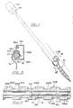
- the spindle 10 is either as shown in Fig. 3, for supporting garment hangers 16 or the like, or for driving hangers or the like along a support rail and the spindle is supported by means of a profiled bar 18 of the cross section shown in Fig. 2 comprising a base portion 18A, a rear wall portion 18B, a top portion 18C and a down turned flange 18D.
- the profiled support bar 18 is open at one side as shown in Fig. 3 in order to permit the hanger 16 to be supported and transported by the spindle.
- the spindle is made up of a number of interconnected sections e.g. of the order of 2 m long, and Fig. 2 illustrates how the spindle sections are connected.
- the ends of two spindle sections 10A and 10B are shown, each section comprising an outer plastic sleeve 26A, 26B in which is provided a rigidifying spine 28A, 28B of mild steel or the like which enhances the torsional rigidity of the section, and finally a coupling rod 30 is provided for coupling the section ends.
- the sleeves 26A, 26B are as shown provided with scroll grooves 32A, 32B, and the sections must be mated together at the zone 34 so that the scroll groove 32A forms a smooth continuation of scroll groove 32B.
- the rigidifying steel tube 28A overhangs the end of the sleeve 26A by the distance X as shown, and the rod 30 overhangs the end of the rigidifying tube 28A also by the amount X.
- the end which is coupled to the end of section 10A is arranged so that the rigidifying tube 28B is located inside the sleeve 26B so that the sleeve in fact overhangs the rigidifying spine 28B by the amount X so that in fact when the two sections are coupled as shown in Fig.
- the sleeves 26A and 26B abut in region 34 which is displaced by the distance X from the region 36 where the reinforcing spines 28A and 28B abut, and the coupling rod 30 extends by an amount X to each side of the region 36.
- pins or screws or the like are passed through the overlapping portions in the positions indicated by the dotted lines and the reference numerals 38 and 40. These pins may be for example split pins.
- the resulting scroll spindle has high torsional rigidity, and therefore will not be subjected to the same degree of wind-up as is a conventional all plastic scroll spindle.
- the pitching of the threads on the scroll spindle can be varied to suit the particular use to which the spindle is to be put.
Landscapes
- Engineering & Computer Science (AREA)
- Mechanical Engineering (AREA)
- Holders For Apparel And Elements Relating To Apparel (AREA)
Applications Claiming Priority (2)
| Application Number | Priority Date | Filing Date | Title |
|---|---|---|---|
| GB8722851A GB8722851D0 (en) | 1987-09-29 | 1987-09-29 | Scroll drives |
| GB8722851 | 1987-09-29 |
Publications (1)
| Publication Number | Publication Date |
|---|---|
| EP0312721A1 true EP0312721A1 (fr) | 1989-04-26 |
Family
ID=10624521
Family Applications (1)
| Application Number | Title | Priority Date | Filing Date |
|---|---|---|---|
| EP19880112856 Withdrawn EP0312721A1 (fr) | 1987-09-29 | 1988-08-06 | Tige filetée de transport |
Country Status (2)
| Country | Link |
|---|---|
| EP (1) | EP0312721A1 (fr) |
| GB (1) | GB8722851D0 (fr) |
Cited By (2)
| Publication number | Priority date | Publication date | Assignee | Title |
|---|---|---|---|---|
| EP0416348A1 (fr) * | 1989-09-02 | 1991-03-13 | Dürkopp Adler Aktiengesellschaft | Transporteur |
| DE4320501A1 (de) * | 1993-06-21 | 1994-12-22 | Sim Zufuehr Und Montagetechnik | Anlage für die Bearbeitung und/oder Montage von auf einem Werkstückträger angeordneten Werkstücken |
Citations (5)
| Publication number | Priority date | Publication date | Assignee | Title |
|---|---|---|---|---|
| DE1525201A1 (de) * | 1966-03-11 | 1969-12-18 | Nydqvist & Holm Ab | Gehaertete Schraube |
| US3705644A (en) * | 1970-01-23 | 1972-12-12 | Claude Edward Kawchitch | Conveyor screw element |
| US3844406A (en) * | 1972-11-17 | 1974-10-29 | Kornylah Corp | Rotating cable conveyor |
| DE7507855U (fr) * | 1975-08-28 | Meuser J | ||
| GB2188017A (en) * | 1986-02-25 | 1987-09-23 | Stockrail Services Ltd | Improvements relating to live storage devices |
-
1987
- 1987-09-29 GB GB8722851A patent/GB8722851D0/en active Pending
-
1988
- 1988-08-06 EP EP19880112856 patent/EP0312721A1/fr not_active Withdrawn
Patent Citations (5)
| Publication number | Priority date | Publication date | Assignee | Title |
|---|---|---|---|---|
| DE7507855U (fr) * | 1975-08-28 | Meuser J | ||
| DE1525201A1 (de) * | 1966-03-11 | 1969-12-18 | Nydqvist & Holm Ab | Gehaertete Schraube |
| US3705644A (en) * | 1970-01-23 | 1972-12-12 | Claude Edward Kawchitch | Conveyor screw element |
| US3844406A (en) * | 1972-11-17 | 1974-10-29 | Kornylah Corp | Rotating cable conveyor |
| GB2188017A (en) * | 1986-02-25 | 1987-09-23 | Stockrail Services Ltd | Improvements relating to live storage devices |
Cited By (3)
| Publication number | Priority date | Publication date | Assignee | Title |
|---|---|---|---|---|
| EP0416348A1 (fr) * | 1989-09-02 | 1991-03-13 | Dürkopp Adler Aktiengesellschaft | Transporteur |
| US5078262A (en) * | 1989-09-02 | 1992-01-07 | Durkopp Adler Aktiengesellschaft | Conveyor |
| DE4320501A1 (de) * | 1993-06-21 | 1994-12-22 | Sim Zufuehr Und Montagetechnik | Anlage für die Bearbeitung und/oder Montage von auf einem Werkstückträger angeordneten Werkstücken |
Also Published As
| Publication number | Publication date |
|---|---|
| GB8722851D0 (en) | 1987-11-04 |
Similar Documents
| Publication | Publication Date | Title |
|---|---|---|
| US5009306A (en) | Printed circuit board conveyor and method | |
| US7686156B2 (en) | Slip tube system for adjusting drive force of shaft driven conveyor system | |
| EP1713704B1 (fr) | Dispositif transporteur | |
| KR0177540B1 (ko) | 반송 설비 | |
| US11008176B1 (en) | Slip roller conveyor | |
| RU2118285C1 (ru) | Конвейер с подвесной лентой | |
| US20020185031A1 (en) | Trolley-type monorail conveyor system | |
| EP0842875A1 (fr) | Convoyeur pour bouteilles orientées | |
| US6578704B1 (en) | Belts and belt modules for spiral conveyors | |
| US4354575A (en) | Goods conveyor track | |
| US4505381A (en) | Conveyor roller | |
| EP0312721A1 (fr) | Tige filetée de transport | |
| CA2175189C (fr) | Transporteur a bande en forme de tuyau flexible et ensemble d'entrainement associe | |
| SE502781C2 (sv) | Universalbalk för rörlig last | |
| EP0275564A1 (fr) | Ensemble de transporteur | |
| US5586639A (en) | Powered roller conveyer for light loads | |
| JP2001514144A (ja) | コンベヤ | |
| US5456346A (en) | Continuous conveyor for transporting individual hangers | |
| US4936441A (en) | Vertical type conveyor | |
| US6032785A (en) | Overhead conveyor system | |
| EP0335906B1 (fr) | Agencement de voie de convoyage avec chariots suspendus | |
| CA1220153A (fr) | Rouleau de transporteur | |
| AU6282194A (en) | A parcels conveyor | |
| DE3721658A1 (de) | Laufschienenanordnung eines haengefoerdersystems | |
| US5341918A (en) | Article transfer device |
Legal Events
| Date | Code | Title | Description |
|---|---|---|---|
| PUAI | Public reference made under article 153(3) epc to a published international application that has entered the european phase |
Free format text: ORIGINAL CODE: 0009012 |
|
| AK | Designated contracting states |
Kind code of ref document: A1 Designated state(s): AT BE CH DE ES FR GB GR IT LI LU NL SE |
|
| 17P | Request for examination filed |
Effective date: 19891004 |
|
| STAA | Information on the status of an ep patent application or granted ep patent |
Free format text: STATUS: THE APPLICATION IS DEEMED TO BE WITHDRAWN |
|
| 18D | Application deemed to be withdrawn |
Effective date: 19910228 |