EP0312745A2 - Dampfreduzierung aus Gasströmen durch Erstarrung - Google Patents
Dampfreduzierung aus Gasströmen durch Erstarrung Download PDFInfo
- Publication number
- EP0312745A2 EP0312745A2 EP88114303A EP88114303A EP0312745A2 EP 0312745 A2 EP0312745 A2 EP 0312745A2 EP 88114303 A EP88114303 A EP 88114303A EP 88114303 A EP88114303 A EP 88114303A EP 0312745 A2 EP0312745 A2 EP 0312745A2
- Authority
- EP
- European Patent Office
- Prior art keywords
- chilled liquid
- liquid
- melting point
- vapors
- chilled
- Prior art date
- Legal status (The legal status is an assumption and is not a legal conclusion. Google has not performed a legal analysis and makes no representation as to the accuracy of the status listed.)
- Withdrawn
Links
Images

Classifications
-
- B—PERFORMING OPERATIONS; TRANSPORTING
- B01—PHYSICAL OR CHEMICAL PROCESSES OR APPARATUS IN GENERAL
- B01D—SEPARATION
- B01D8/00—Cold traps; Cold baffles
-
- B—PERFORMING OPERATIONS; TRANSPORTING
- B01—PHYSICAL OR CHEMICAL PROCESSES OR APPARATUS IN GENERAL
- B01D—SEPARATION
- B01D53/00—Separation of gases or vapours; Recovering vapours of volatile solvents from gases; Chemical or biological purification of waste gases, e.g. engine exhaust gases, smoke, fumes, flue gases, aerosols
- B01D53/002—Separation of gases or vapours; Recovering vapours of volatile solvents from gases; Chemical or biological purification of waste gases, e.g. engine exhaust gases, smoke, fumes, flue gases, aerosols by condensation
Definitions
- the present invention relates to a process and apparatus for abatement of warm melting point vapors from gas streams.
- the heat exchange between the effluent gas stream and the cryogenic liquid may be direct or indirect.
- the heat exchange method is typically indirect if it is desired to maintain the cryogenic material at pressure and/or free from contamination so the vaporized cryogen can be re-used in other processes.
- a commonly used process for indirect heat transfer employs a shell and tube heat exchanger, wherein a liquid or partially vaporized cryogen flows through one side of the exchanger and the effluent gas flows through the other side of the exchanger.
- Direct heat exchange between the liquid cryogen and the effluent gas can be accomplished using any method by which the liquid cryogen contacts the effluent gas, such as a downward spray of the liquid cryogen upon an upwardly rising volume of gas.
- U.K. Patent No. 1,582,955 to R.W. Watson et al. entitled: CONDENSATION OF THE VAPOR OF A VOLATILE LIQUID, describes processes like those discussed above in more detail.
- Banerjee entitled Heat Exchange Methods and Apparatus
- U.S. Patent No. 3,535,345 to R. B. Eghert entitled Method of Producing Phthalic Anhydride, and published patent disclosure, Federal Republic of Germany, P 24 11 601.6, K.M. Pohl, entitled Process For The Reduction of Emissions During The Storage and Loading of Volatile Liquids And Device For Carrying Out Such Process.
- cryogenic liquid a liquid with a normal boiling temperature below about -200°F
- cryogenic technology is deliberately restricted to avoid the solidification of volatile materials in the incoming gas stream upon defined heat exchange surfaces (which would foul the exchange surfaces).
- One approach to the fouling problem has been to eliminate the defined heat exchange surfaces by directly contacting the incoming gas stream or its refluxed condensate with vaporizing cryogen. This approach causes loss of cryogen pressure and contamination of the cryogen by constituents of the gas stream.
- the vaporized cryogen used in this direct contact approach is typically vented to atmosphere.
- the non-recoverability of the cryogen for use as a clean gas at pressure adds greatly to process cost and adds to the volume of gas containing volatiles which is vented to atmosphere.
- the relatively large gas volume of the vaporizing cryogen tends to loft condensate droplets of the volatiles to be recovered out of the condenser, subverting the process objective which is volatile abatement or recovery.
- the above references recommend use of a liquid condensate of one or more of the volatile constituents of the incoming gas stream as the chilled fluid.
- the references also recommend the removal of any materials which freeze at high temperatures (such as moisture at 32°F) from both the intermediary fluid and the incoming gas stream prior to implementation of the volatiles recovery method, to avoid freezing of such materials and fouling of indirect heat exchange surfaces between the chilled intermediary fluid and the vaporizing cryogen.
- the temperature of the warm end of the heat exchanger (where the intermediary fluid first enters the exchanger) be controlled to be at least 32°F to prevent freezing out of any moisture at this location in the exchanger.
- cryogenic processes for volatiles reduction require continuous operation.
- the methods of volatiles reduction from gas streams disclosed in the cited art require at least one of the following: 1) a pretreatment of the gas stream to remove moisture and/or other high melting point volatiles; 2) limitation of the heat exchange temperature within at least a portion of the volatiles recovery operation to temperatures above the warmest melting point of gas stream volatile materials; 3) duplication of heat exchange equipment to permit regeneration (solids removal from) of heat exchange surfaces.
- Substantial economies both in terms of capital equipment outlay and/or in costs of operation can be achieved by eliminating the need for any of the three above means within the cryogenic process for volatiles removal.
- the present invention provides a process and apparatus for the reduction or abatement of warm melting point vapors from gas streams.
- the warm melting point vapors are solidified by direct contact between the gas stream and a chilled liquid, and are subsequently removed from the chilled liquid using conventional liquid-solids separation techniques.
- the chilled liquid must exhibit a vapor pressure at the contacting temperature which is low enough to preclude unsafe or uneconomic levels of the chilled liquid vapor in the processed gas stream.
- the chilled liquid is recycled within the process, wherein it is cooled using indirect heat exchange with a cryogenic liquid.
- the temperature at which the vapors are removed is significantly lower, thereby reducing the vapor pressure of both the warm melting point vapors and the chilled liquid used to remove them from the effluent gas stream.
- These lower vapor pressure result in a processed gas stream containing reduced warm melting point vapor and reduced chilled liquid components.
- Selection of a chilled liquid in which the solidified warm melting point vapors have minimal solubility is helpful in reducing the warm melting point vapor content of the recycled chilled liquid (thereby further reducing the warm melting point vapor content of the processed gas stream) and in reducing the viscosity of the chilled liquid in some cases, thereby improving fluid flow characteristics in the chilled liquid recycle loop.
- Contacting temperature the temperature of the chilled liquid as it is brought into contact with the incoming gas stream to the volatiles reduction process.
- the contacting temperature is determined by the specific volatiles content limitations placed on the gas stream exiting the volatiles reduction process.
- Warm melting point vapors the constituents of the gas stream incoming to the volatiles reduction process whose melting points are above the intermediary cooling liquid contacting temperature, and which thus solidify upon contacting said liquid.
- Ni(CO)4 nickel carbonyl
- SeOF2 selenium oxyfluoride
- VCl4 vanadium tetrachloride
- Chilled liquid the liquid used to solidify at least a portion of the vapors/volatiles in the incoming gas stream with which the chilled liquid is contacted. Note that some vapors/volatiles may be condensed upon contact with the chilled liquid incidental to the warm melting point vapors which are solidified.
- the chilled liquid melting point must be lower than the melting point temperature of any of the warm melting point vapors intended to be removed or abated from the incoming gas stream, and should typically be substantially below such vapor melting points, to minimize the potential build of frozen (solidified) chilled liquid on the vaporizing cryogen indirect heat exchange surface.
- the actual bulk temperature of the chilled liquid will typically be maintained at or slightly below the contacting temperature.
- the vapor pressure of the chilled liquid at the contacting temperature must be sufficiently low to preclude unsafe levels of chilled liquid in the gas stream exiting the process.
- the viscosity of the chilled liquid at the bulk temperature should be sufficiently low to permit it to be pumped and to efficiently contact the gas stream within the volatiles reduction process.
- Unsafe levels of the chilled liquid vapors in the gas stream exiting the process concentrations of chilled liquid vapors which exceed applicable health or flammability standards designated to protect persons and property.
- TLV threshold limit values
- Cryogenic Liquid a liquified atmospheric component such as nitrogen, oxygen or argon, supplied at a temperature below about - 200°F.
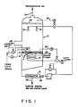
- Fig. 1 illustrates a preferred embodiment of apparatus, in accordance with the present invention, for removal of warm melting point vapors from a process gas stream by solidification (freezing-out).
- the device enabling heat exchange between the intermediary chilled liquid and vaporizing cryogen (illustrated as a coil of tubing) is contained within the vessel used for direct contact heat exchange between the incoming gas stream and the intermediary chilled liquid.
- Fig. 2 illustrates a second apparatus preferred embodiment similar to that shown in Fig. 1; however, the device used to remove heat from the intermediary chilled liquid is located in a separate sealed vessel, to increase protection of the heat exchange surface of the device from the deposition of solidified warm melting point vapors.
- the preferred process of the present invention comprises directly contacting a gas stream containing vapors/volatiles to be abated with a chilled liquid which is not a constituent of the vapors to be abated.
- the contacting chilled liquid is supplied at a temperature below the melting point of at least one of the constituents to be removed from the vapor stream.
- the contacting liquid must therefore have a melting point below the melting point of the vapors/volatiles to be removed by solidification.
- the contacting liquid must also have a vapor pressure at the contacting temperature which is low enough to preclude unsafe levels of its vapor in the processed gas stream.
- the contacting liquid should have a vapor pressure at the contacting temperature which does not result in uneconomical levels of its vapor in the processed gas stream. Chilled liquid which is carried out of the process along with the solidified warm melting point vapors (which are separated from the bulk of the chilled liquid and removed from the process) must be replaced during operation of the process, thereby representing a process cost.
- the above preferred process enables the use of a temperature differential between the selected chilled liquid and the warm melting point vapors which is directly designed to optimize vapors/volatiles reduction to meet specific standards such as the TLV standards applied to the gas stream exiting the volatiles recovery process.
- the chilled liquid to be used can be selected based on physical and chemical data available from reference sources commonly used in the art.
- the chilled liquid is the condensate of any of the condensables in the incoming gas stream whose melting points are below the contacting temperature.
- the melting points of the condensate must be sufficiently lower than the melting points of the warm melting point vapors to be removed that the warm melting point vapors are solidified upon direct contact with the condensate.
- the amount of the chilled liquid vapors remaining in the gas stream must not be unsafe and should not be uneconomical.
- the efficiency of separation of the solidified warm melting point vapors from the chilled liquid is less critical in terms of maintaining a given amount of chilled liquid within the process.
- Chilled liquid which is removed from the process along with the solidified warm melting point vapors is replaced at least in part by additional condensate generated during processing of the incoming gas stream, thereby reducing incremental processing costs. Any additional chilled liquid required must be supplied as make up directly to the process.
- the contacting of a gas stream containing warm melting point vapors with a chilled liquid is typically done in a spray tower 10, as shown in Fig. 1, since such a tower is not as susceptible to fouling by solidified warm melting point vapors.
- the contacting device is not limited to a spray tower, however; a plate column, for example, might be used if the flushing action of the contacting chilled liquid is sufficient to prevent fouling. Another option would be to bubble the effluent gas through the contacting chilled liquid.
- the process gas 32 containing the warm melting point vapor is fed into the spray tower 10, wherein it is directly contacted by chilled liquid 24 impinged upon the process gas from the spray nozzles 30.
- the contact of the process gas with the chilled liquid results in solidification or freezing out of the warm melting point vapors, which solidified vapors are carried along with the chilled liquid into the pool of chilled liquid and solidified vapors 12 at the bottom portion of the the spray tower 10.
- the pool 12 comprising the slurry of contacting liquid and frozen vapors, is kept at the contacting temperature (or slightly below contacting temperature) by an immersed refrigeration coil 14.
- Liquid cryogen or vaporizing cryogen provides the cooling medium inside the coil 14.
- liquid cryogen 20 would enter the refrigeration coil 14 and vaporized cryogen 22 would exit the coil.
- the heat exchange device need not be a coil as shown, but can be any indirect heat exchange device known in the industry so long as use of the device does not cause build up of solidified warm melting point vapors on the heat exchange surface of the device to an extent which renders the device inoperable.
- a shroud or screen 18 can be used to prevent the solidified warm melting point vapors from impinging and layering upon the coil 14.
- the solidified warm melting point vapors are removed from the slurry 12 by the separator 16 and sent on for further processing as necessary, depending on the final desired use of the solidified vapors.
- the separator 16 may be any suitable apparatus known in the art, such as a flotation device, a settling tank, a filter, a centrifuge, etc.
- the chilled liquid 24 separated from the solidified warm melting point vapors is recycled to the spray nozzles 30 in the spray tower 10.
- FIG. 2 An alternative apparatus for chilling the contacting liquid is shown in Fig. 2.
- the heat transfer device again shown as a coil 14, is located in a second insulated vessel 42 which is located downstream of the separator 16. This reduces the amount of fouling of the coil 14 by solidified warm melting point vapor impingement.
- Fig. 2 also shows apparatus for removal of excess chilled liquid which may be required if the contacting liquid is the condensate of at least one of the constituents of the incoming gas stream, since the rate of condensation of the contacting liquid constituent may exceed the rate at which condensate leaves the process with the solidified volatiles stream 40.
- Apparatus for removal of excess chilled liquid can also be used in combination with the apparatus shown in Fig. 1.
- a second coil may be located in the pool at the bottom of the spray tower/contactor 10, as shown in Fig. 1 or in the alternate cooling vessel 42 as shown in Fig. 2.
- the second coil can be placed in use while the fouled coil is defrosted either by the warmer bulk temperature of the surrounding liquid or by the action of warm cryogen vapor forced through the fouled coil. It is preferred, however, to select a chilled liquid which reduces or avoids the formation of deposits of chilled liquid on the heat exchange device, thus reducing total equipment costs.
- a list of potential chilled liquids capable of providing the contacting temperature and of meeting vapor pressure requirements at that temperature can be tabulated. Minimal experimentation using techniques known in the art can be conducted to determine which of the chilled liquids on the list will provide minimal deposits of frozen chilled liquid on the heat exchange device (such as a refrigeration coil).
- the contacting chilled liquid 24, is comprised of acetone liquid at about -90°F.
- the process gas 32 is comprised of air containing carbon tetrachloride wherein the concentration of carbon tetrachloride is about 2.0 volume percent.
- Acetone has low solubility in carbon tetrachloride at the contacting temperature (about -90°F) and its low melting point (-140°F) minimizes buildup on the immersed coil 14.
- a shroud or screen 18 can be used to keep the carbon tetrachloride precipitate from building up on the coil 14.
- the liquid cryogen 20 used to cool the slurry 12 comprising acetone and solidified carbon tetrachloride is liquid nitrogen, which enters the coil 14 at a temperature of about -320°F.
- the acetone contacting liquid 24 is directly contacted with the incoming process gas 32 in the form of a spray exiting nozzles 30.
- the direct contact between the acetone contacting liquid 24 and the incoming gas 32 causes solidification of the carbon tetrachloride which is carried with the acetone into the bottom of the spray tower 10, to form a slurry 12 in the bottom of spray tower 10.
- the slurry 12 is processed through a liquid-solids separator 16 (of the kind previously discussed) whereby solidified carbon tetrachloride wet with chilled liquid 40 is removed from the acetone contacting liquid.
- the separated acetone contacting liquid 24 is then pumped to the spray nozzles 30.
- One temperature controller 26 maintains the pool of slurry 12 temperature by varying the liquid nitrogen 20 flow rate, while a second temperature controller 28 maintains the temperature of the leaving effluent 34 by varying the flow to the spray nozzles 30.
- a demister pad 36 may be required to trap any particulates and contacting liquid droplets which are convected up by the leaving noncondensibles stream 34.
- the volume concentration of acetone in the gas 34 exiting the process is about 0.061 volume percent, which value is well below the threshold limit value (TLV) and the lower explosive limit (LEL) for acetone.
- TLV threshold limit value
- LEL lower explosive limit
- a contacting liquid level control system 38 is required for continuous operation to replace contacting chilled liquid lost with the separated solidified warm melting point vapors 40.
- FIG. 2 An alternative apparatus for chilling the contacting liquid 24 is shown in Fig. 2.
- the device for indirect heat exchange between the contacting liquid and the cryogen shown as a refrigeration coil 14, is located in a separate sealed vessel 42.
- the slurry 12 comprising acetone and solidified carbon tetrachloride is processed through the separator 16 to remove the solidified carbon tetrachloride from the acetone contacting liquid.
- the separated acetone contacting liquid 24 is pressured or pumped to the cooling vessel 42 wherein the acetone contacting liquid 24 is chilled by indirect heat transfer with the vaporizing cryogen passing through refrigeration coil 14.
- the amount of ethanol remaining on the granules after filtering was not determined during the above testing, but could be determined by standard analytical techniques or by doing standard material balance calculations for measured water and ethanol quantities at various steps during the determination.
- the process of the present invention requires that the solidified warm melting point vapors be separable from the slurry of warm melting point vapors and contacting chilled liquid.
- the warm melting point vapors removed may comprise only a portion of the total volatiles to be removed from the incoming gas and other volatiles to be removed may be condensed and removed as part of the slurry formed in the bottom of the spray tower.
- Such condensed volatiles may be separated from the contacting liquid using standard liquid-liquid separation techniques prior to recycle of the contacting liquid to the spray nozzles, or such condensed volatiles may be used as at least part of the contacting liquid.
Landscapes
- Chemical & Material Sciences (AREA)
- Chemical Kinetics & Catalysis (AREA)
- Engineering & Computer Science (AREA)
- Analytical Chemistry (AREA)
- General Chemical & Material Sciences (AREA)
- Oil, Petroleum & Natural Gas (AREA)
- Vaporization, Distillation, Condensation, Sublimation, And Cold Traps (AREA)
- Physical Or Chemical Processes And Apparatus (AREA)
Applications Claiming Priority (2)
| Application Number | Priority Date | Filing Date | Title |
|---|---|---|---|
| US07/110,845 US4769054A (en) | 1987-10-21 | 1987-10-21 | Abatement of vapors from gas streams by solidification |
| US110845 | 1987-10-21 |
Publications (2)
| Publication Number | Publication Date |
|---|---|
| EP0312745A2 true EP0312745A2 (de) | 1989-04-26 |
| EP0312745A3 EP0312745A3 (de) | 1989-07-26 |
Family
ID=22335249
Family Applications (1)
| Application Number | Title | Priority Date | Filing Date |
|---|---|---|---|
| EP88114303A Withdrawn EP0312745A3 (de) | 1987-10-21 | 1988-09-01 | Dampfreduzierung aus Gasströmen durch Erstarrung |
Country Status (6)
| Country | Link |
|---|---|
| US (1) | US4769054A (de) |
| EP (1) | EP0312745A3 (de) |
| JP (1) | JPH01143601A (de) |
| KR (1) | KR930003209B1 (de) |
| BR (1) | BR8803592A (de) |
| CA (1) | CA1283600C (de) |
Cited By (2)
| Publication number | Priority date | Publication date | Assignee | Title |
|---|---|---|---|---|
| EP1388361A3 (de) * | 2002-08-09 | 2004-05-06 | Tsukishima Kikai Co., Ltd. | Anlage zur aufnahme vom gaskomponenten mit hohem Schmelzpunkt in einem Gasstrom und Anlage zur Aufnahme von dihalogenierte aromatische Verbindungen in einem Gasstrom |
| EP1686338A3 (de) * | 2000-06-20 | 2009-11-25 | Air Products and Chemicals, Inc. | Verfahren und Vorrichtung, um flüchtige Komponenten aus einem Gasstrom zu entfernen |
Families Citing this family (57)
| Publication number | Priority date | Publication date | Assignee | Title |
|---|---|---|---|---|
| US5291751A (en) * | 1992-04-21 | 1994-03-08 | Liquid Carbonic Corporation | Cryo-mechanical vapor recovery apparatus |
| ES2075808B1 (es) * | 1994-01-11 | 1996-05-01 | Franco Eusebio Moro | Sistema de filtracion de particulas residuales contaminantes para humos y gases, mediante ultracongelacion atomizada. |
| US5540057A (en) * | 1995-06-30 | 1996-07-30 | Praxair Technology, Inc. | Volatile organic compounds recovery from vent gas streams |
| US5634355A (en) * | 1995-08-31 | 1997-06-03 | Praxair Technology, Inc. | Cryogenic system for recovery of volatile compounds |
| US5638698A (en) * | 1996-08-22 | 1997-06-17 | Praxair Technology, Inc. | Cryogenic system for producing nitrogen |
| AU1015999A (en) * | 1998-11-03 | 2000-05-22 | Chemical Vapour Deposition Systems Inc. | Nickel carbonyl vapour deposition apparatus and process |
| US6132518A (en) * | 1998-11-04 | 2000-10-17 | Chemical Vapour Deposition Systems, Inc. | Nickel carbonyl vapour deposition apparatus and method |
| US7246497B2 (en) * | 2004-06-16 | 2007-07-24 | Lytron, Inc. | Mist generation, freezing, and delivery system |
| FR2894838B1 (fr) * | 2005-12-21 | 2008-03-14 | Gaz De France Sa | Procede et systeme de capture du dioxyde de carbone present dans des fumees |
| US20070215364A1 (en) * | 2006-03-17 | 2007-09-20 | Hatsuta Seisakusho Co., Ltd. | Fire-extinguishing method of a pool fire |
| US8715401B2 (en) | 2009-03-16 | 2014-05-06 | Sustainable Energy Solutions, Llc | Methods and systems for separating condensable vapors from gases |
| AU2010239718B2 (en) | 2009-04-20 | 2016-02-04 | Exxonmobil Upstream Research Company | Cryogenic system for removing acid gases from a hyrdrocarbon gas stream, and method of removing acid gases |
| EA024440B1 (ru) | 2009-09-09 | 2016-09-30 | Эксонмобил Апстрим Рисерч Компани | Криогенная система для удаления кислотных газов из потока газообразных углеводородов |
| CN102740941A (zh) * | 2010-02-03 | 2012-10-17 | 埃克森美孚上游研究公司 | 使用冷却液从工艺气流中去除可凝固的气体组分的系统和方法 |
| EP2640488B1 (de) | 2010-11-19 | 2019-03-27 | Sustainable Energy Solutions, LLC | Systeme und verfahren zur trennung von kondensierbaren dämpfen aus gasen durch direktkontakt-wärmeaustausch |
| EP2866921B1 (de) | 2011-05-26 | 2026-04-22 | Sustainable Energy Solutions, LLC | System zur trennung von kondensierbaren dämpfen von leichten gasen oder flüssigkeiten durch rekuperative kryogene verfahren |
| KR101354188B1 (ko) * | 2012-03-19 | 2014-01-23 | 주식회사 포스코 | 에너지 회수형 냉각탑 및 이를 이용한 에너지 회수방법 |
| WO2013142100A1 (en) | 2012-03-21 | 2013-09-26 | Exxonmobil Upstream Research Company | Separating carbon dioxide and ethane from a mixed stream |
| FR3004964A1 (fr) * | 2013-04-30 | 2014-10-31 | Salah Hassanin | Systeme de purification des fumees emanant des usines par refroidissement et intensification. |
| US9562719B2 (en) | 2013-12-06 | 2017-02-07 | Exxonmobil Upstream Research Company | Method of removing solids by modifying a liquid level in a distillation tower |
| US9752827B2 (en) | 2013-12-06 | 2017-09-05 | Exxonmobil Upstream Research Company | Method and system of maintaining a liquid level in a distillation tower |
| EA031531B1 (ru) | 2013-12-06 | 2019-01-31 | Эксонмобил Апстрим Рисерч Компани | Способ и устройство для разделения углеводородов и загрязняющих примесей с помощью нагревательного устройства для дестабилизации и/или предотвращения адгезии твердых веществ |
| US9874395B2 (en) | 2013-12-06 | 2018-01-23 | Exxonmobil Upstream Research Company | Method and system for preventing accumulation of solids in a distillation tower |
| MY177751A (en) | 2013-12-06 | 2020-09-23 | Exxonmobil Upstream Res Co | Method and device for separating a feed stream using radiation detectors |
| MY176633A (en) | 2013-12-06 | 2020-08-19 | Exxonmobil Upstream Res Co | Method and system of modifiying a liquid level during start-up operations |
| US9803918B2 (en) | 2013-12-06 | 2017-10-31 | Exxonmobil Upstream Research Company | Method and system of dehydrating a feed stream processed in a distillation tower |
| MX363830B (es) | 2013-12-06 | 2019-04-04 | Exxonmobil Upstream Res Co | Metodo y dispositivo para separar hidrocarburos y contaminantes con un ensamblaje de rocio. |
| WO2015084498A2 (en) | 2013-12-06 | 2015-06-11 | Exxonmobil Upstream Research Company | Method and system for separating a feed stream with a feed stream distribution mechanism |
| CN107208964B (zh) | 2015-02-27 | 2020-06-19 | 埃克森美孚上游研究公司 | 减少进入低温蒸馏过程的进料物流的冷冻和脱水负荷 |
| CA2994812C (en) | 2015-09-18 | 2020-03-10 | Exxonmobil Upstream Research Company | Heating component to reduce solidification in a cryogenic distillation system |
| US11255603B2 (en) | 2015-09-24 | 2022-02-22 | Exxonmobil Upstream Research Company | Treatment plant for hydrocarbon gas having variable contaminant levels |
| EA201892054A1 (ru) | 2016-03-30 | 2019-02-28 | Эксонмобил Апстрим Рисерч Компани | Поступающая из собственных источников пластовая текучая среда для повышения нефтеотдачи |
| GB2553277B (en) * | 2016-08-17 | 2020-01-08 | Pmw Tech Ltd | Apparatus for desubliming carbon dioxide |
| US10465984B2 (en) * | 2017-01-23 | 2019-11-05 | Hall Labs Llc | Circulating fluidized bed connected to a desublimating heat exchanger |
| JP6858267B2 (ja) | 2017-02-24 | 2021-04-14 | エクソンモービル アップストリーム リサーチ カンパニー | 二重目的lng/lin貯蔵タンクのパージ方法 |
| US10543456B2 (en) * | 2017-04-24 | 2020-01-28 | Hall Labs Llc | Method for separating components using solids producing multi-stage direct and indirect-contact exchange |
| US20180328661A1 (en) * | 2017-05-11 | 2018-11-15 | Larry Baxter | Method for Removing Foulants from a Heat Exchanger through Coolant Flow Control |
| US20190170440A1 (en) * | 2017-12-05 | 2019-06-06 | Larry Baxter | Pressure-Regulated Melting of Solids |
| US20190170441A1 (en) * | 2017-12-05 | 2019-06-06 | Larry Baxter | Pressure-Regulated Melting of Solids with Warm Fluids |
| MY204021A (en) | 2018-06-07 | 2024-08-01 | Exxonmobil Upstream Res Co | Pretreatment and pre-cooling of natural gas by high pressure compression and expansion |
| US11306267B2 (en) | 2018-06-29 | 2022-04-19 | Exxonmobil Upstream Research Company | Hybrid tray for introducing a low CO2 feed stream into a distillation tower |
| WO2020005553A1 (en) | 2018-06-29 | 2020-01-02 | Exxonmobil Upstream Research Company (Emhc-N1.4A.607) | Mixing and heat integration of melt tray liquids in a cryogenic distillation tower |
| AU2019322808B2 (en) | 2018-08-14 | 2022-10-13 | ExxonMobil Technology and Engineering Company | Conserving mixed refrigerant in natural gas liquefaction facilities |
| MY208562A (en) | 2018-08-22 | 2025-05-15 | Exxonmobil Upstream Res Co | Managing make-up gas composition variation for a high pressure expander process |
| EP3841343A2 (de) | 2018-08-22 | 2021-06-30 | ExxonMobil Upstream Research Company | Wärmetauscherkonfiguration für hochdruckexpanderverfahren und verfahren zur erdgasverflüssigung unter verwendung derselben |
| JP7179155B2 (ja) | 2018-08-22 | 2022-11-28 | エクソンモービル アップストリーム リサーチ カンパニー | 高圧エキスパンダプロセスのための一次ループ始動方法 |
| WO2020106394A1 (en) | 2018-11-20 | 2020-05-28 | Exxonmobil Upstream Research Company | Poly refrigerated integrated cycle operation using solid-tolerant heat exchangers |
| WO2020106397A1 (en) | 2018-11-20 | 2020-05-28 | Exxonmobil Upstream Research Company | Methods and apparatus for improving multi-plate scraped heat exchangers |
| US11668524B2 (en) | 2019-01-30 | 2023-06-06 | Exxonmobil Upstream Research Company | Methods for removal of moisture from LNG refrigerant |
| EP3918261A1 (de) | 2019-01-30 | 2021-12-08 | Exxonmobil Upstream Research Company (EMHC-N1-4A-607) | Verfahren zur entfernung von feuchtigkeit aus lng-kältemittel |
| US11465093B2 (en) | 2019-08-19 | 2022-10-11 | Exxonmobil Upstream Research Company | Compliant composite heat exchangers |
| US20210063083A1 (en) | 2019-08-29 | 2021-03-04 | Exxonmobil Upstream Research Company | Liquefaction of Production Gas |
| US12050054B2 (en) | 2019-09-19 | 2024-07-30 | ExxonMobil Technology and Engineering Company | Pretreatment, pre-cooling, and condensate recovery of natural gas by high pressure compression and expansion |
| WO2021055021A1 (en) | 2019-09-19 | 2021-03-25 | Exxonmobil Upstream Research Company | Pretreatment and pre-cooling of natural gas by high pressure compression and expansion |
| US11806639B2 (en) | 2019-09-19 | 2023-11-07 | ExxonMobil Technology and Engineering Company | Pretreatment and pre-cooling of natural gas by high pressure compression and expansion |
| US11083994B2 (en) | 2019-09-20 | 2021-08-10 | Exxonmobil Upstream Research Company | Removal of acid gases from a gas stream, with O2 enrichment for acid gas capture and sequestration |
| KR20220062653A (ko) | 2019-09-24 | 2022-05-17 | 엑손모빌 업스트림 리서치 캄파니 | 선박의 이중 목적 극저온 탱크 또는 lng 및 액화 질소용 부유식 저장 유닛용 화물 스트리핑 기능 |
Family Cites Families (16)
| Publication number | Priority date | Publication date | Assignee | Title |
|---|---|---|---|---|
| US3126334A (en) * | 1964-03-24 | Process and apparatus for melting | ||
| US2507632A (en) * | 1944-11-30 | 1950-05-16 | Eastman Kodak Co | Process for dehydrating materials under low-pressure conditions |
| DE1124015B (de) * | 1959-03-06 | 1962-02-22 | Maschb Anstalt Venuleth & Elle | Verfahren und Vorrichtung zur UEberfuehrung von aus Trocknern oder Verdampfern stammenden Brueden in den festen Aggregatzustand |
| US3344616A (en) * | 1963-08-23 | 1967-10-03 | Owen Margaret Louise | Desalinization |
| US3400512A (en) * | 1966-07-05 | 1968-09-10 | Phillips Petroleum Co | Method for removing water and hydrocarbons from gaseous hci |
| DE1517545A1 (de) * | 1966-11-30 | 1970-01-22 | Linde Ag | Verfahren und Vorrichtung zur Meerwasserentsalzung bei gleichzeitiger Verdampfung tiefsiedender Fluessigkeiten,insbesondere fluessigem Naturgas |
| US3535345A (en) * | 1967-08-15 | 1970-10-20 | Badger Co | Method of producing phthalic anhydride |
| CS154907B1 (de) * | 1970-05-12 | 1974-04-30 | ||
| US4001116A (en) * | 1975-03-05 | 1977-01-04 | Chicago Bridge & Iron Company | Gravitational separation of solids from liquefied natural gas |
| GB1549181A (en) * | 1975-07-23 | 1979-08-01 | Bp Chem Int Ltd | Method and apparatus for the recovery of volatile liquids |
| US4061531A (en) * | 1975-12-12 | 1977-12-06 | Richard Jablin | Coke oven gas contact with liquor concentrate |
| GB1582955A (en) * | 1976-07-28 | 1981-01-21 | Boc Ltd | Condensation of the vapour of a volatile liquid |
| AU511678B2 (en) * | 1977-08-29 | 1980-08-28 | Airco Inc. | Recovering solvents from drying ovens |
| US4237700A (en) * | 1979-04-20 | 1980-12-09 | Airco, Inc. | Methods and apparatus for providing refrigeration |
| US4551981A (en) * | 1981-05-20 | 1985-11-12 | The Boc Group, Inc. | Heat exchange methods and apparatus |
| US4464904A (en) * | 1983-05-19 | 1984-08-14 | Union Carbide Corporation | Process for the transfer of refrigeration |
-
1987
- 1987-10-21 US US07/110,845 patent/US4769054A/en not_active Expired - Fee Related
-
1988
- 1988-07-18 BR BR8803592A patent/BR8803592A/pt not_active Application Discontinuation
- 1988-08-29 JP JP63212654A patent/JPH01143601A/ja active Pending
- 1988-08-29 KR KR1019880011013A patent/KR930003209B1/ko not_active Expired - Lifetime
- 1988-08-29 CA CA000575935A patent/CA1283600C/en not_active Expired - Lifetime
- 1988-09-01 EP EP88114303A patent/EP0312745A3/de not_active Withdrawn
Cited By (3)
| Publication number | Priority date | Publication date | Assignee | Title |
|---|---|---|---|---|
| EP1686338A3 (de) * | 2000-06-20 | 2009-11-25 | Air Products and Chemicals, Inc. | Verfahren und Vorrichtung, um flüchtige Komponenten aus einem Gasstrom zu entfernen |
| EP1388361A3 (de) * | 2002-08-09 | 2004-05-06 | Tsukishima Kikai Co., Ltd. | Anlage zur aufnahme vom gaskomponenten mit hohem Schmelzpunkt in einem Gasstrom und Anlage zur Aufnahme von dihalogenierte aromatische Verbindungen in einem Gasstrom |
| KR100566365B1 (ko) * | 2002-08-09 | 2006-03-31 | 츠키시마기카이가부시키가이샤 | 기체 중의 고융점 성분의 포집 설비 및 기체중의디할로겐화 방향족 화합물의 포집 설비 |
Also Published As
| Publication number | Publication date |
|---|---|
| US4769054A (en) | 1988-09-06 |
| EP0312745A3 (de) | 1989-07-26 |
| KR890006274A (ko) | 1989-06-12 |
| BR8803592A (pt) | 1989-05-23 |
| KR930003209B1 (ko) | 1993-04-23 |
| JPH01143601A (ja) | 1989-06-06 |
| CA1283600C (en) | 1991-04-30 |
Similar Documents
| Publication | Publication Date | Title |
|---|---|---|
| US4769054A (en) | Abatement of vapors from gas streams by solidification | |
| US4980032A (en) | Distillation method and apparatus for reprocessing sulfuric acid | |
| US4417909A (en) | Gas separation process | |
| US6960242B2 (en) | CO2 recovery process for supercritical extraction | |
| AU2006291954C1 (en) | Process and apparatus for removal of sour species from a natural gas stream | |
| US20030133864A1 (en) | Central carbon dioxide purifier | |
| US4424680A (en) | Inexpensive method of recovering condensable vapors with a liquified inert gas | |
| US6490883B2 (en) | Process and apparatus for removal of volatile compounds from process gases | |
| JPH037717B2 (de) | ||
| US5634355A (en) | Cryogenic system for recovery of volatile compounds | |
| US4238211A (en) | Method of employing a first contaminant to prevent freeze-out of a second contaminant during cryogenic processing of a gaseous stream | |
| US4932984A (en) | Process for reduction of chlorinated solvent emissions | |
| US20070128103A1 (en) | Method and Apparatus for Corrosive Gas Purification | |
| US5061348A (en) | Sulfuric acid reprocessor with continuous purge of second distillation vessel | |
| US5820748A (en) | Safe removal of gasses, water and solvents from used lubricating oils with vacuum apparatus under mild temperature conditions | |
| JPH02298302A (ja) | 高度に圧縮されたガス中の粒子から凝縮可能な蒸気を分離する方法 | |
| US4420317A (en) | Process for recovering vaporized solvent which eliminates heat exchangers | |
| US3179662A (en) | Purification of cyanuric chloride | |
| GB1081579A (en) | Method and apparatus for fractional sublimation | |
| US2431866A (en) | Separation of the constituents of gaeous mixtures | |
| US5979179A (en) | Device and method for purifying a gas or vapor flow | |
| US20070072770A1 (en) | Adsorbent for Removing Water Vapor During Corrosive Gas Purification and Method for Preparing the Adsorbent | |
| US3010286A (en) | Process and apparatus for purifying gases | |
| RU2048846C1 (ru) | Способ тонкой очистки веществ кристаллизацией | |
| US2960835A (en) | Separation of gaseous mixtures |
Legal Events
| Date | Code | Title | Description |
|---|---|---|---|
| PUAI | Public reference made under article 153(3) epc to a published international application that has entered the european phase |
Free format text: ORIGINAL CODE: 0009012 |
|
| AK | Designated contracting states |
Kind code of ref document: A2 Designated state(s): BE DE ES FR GB IT SE |
|
| PUAL | Search report despatched |
Free format text: ORIGINAL CODE: 0009013 |
|
| AK | Designated contracting states |
Kind code of ref document: A3 Designated state(s): BE DE ES FR GB IT SE |
|
| 17P | Request for examination filed |
Effective date: 19890825 |
|
| 17Q | First examination report despatched |
Effective date: 19910409 |
|
| STAA | Information on the status of an ep patent application or granted ep patent |
Free format text: STATUS: THE APPLICATION IS DEEMED TO BE WITHDRAWN |
|
| 18D | Application deemed to be withdrawn |
Effective date: 19910820 |