EP0312754B1 - Reformer - Google Patents
Reformer Download PDFInfo
- Publication number
- EP0312754B1 EP0312754B1 EP88114663A EP88114663A EP0312754B1 EP 0312754 B1 EP0312754 B1 EP 0312754B1 EP 88114663 A EP88114663 A EP 88114663A EP 88114663 A EP88114663 A EP 88114663A EP 0312754 B1 EP0312754 B1 EP 0312754B1
- Authority
- EP
- European Patent Office
- Prior art keywords
- reformer
- gas
- catalyst
- reformer according
- oxidation agent
- Prior art date
- Legal status (The legal status is an assumption and is not a legal conclusion. Google has not performed a legal analysis and makes no representation as to the accuracy of the status listed.)
- Expired - Lifetime
Links
Images
Classifications
-
- B—PERFORMING OPERATIONS; TRANSPORTING
- B01—PHYSICAL OR CHEMICAL PROCESSES OR APPARATUS IN GENERAL
- B01J—CHEMICAL OR PHYSICAL PROCESSES, e.g. CATALYSIS OR COLLOID CHEMISTRY; THEIR RELEVANT APPARATUS
- B01J8/00—Chemical or physical processes in general, conducted in the presence of fluids and solid particles; Apparatus for such processes
- B01J8/02—Chemical or physical processes in general, conducted in the presence of fluids and solid particles; Apparatus for such processes with stationary particles, e.g. in fixed beds
-
- C—CHEMISTRY; METALLURGY
- C01—INORGANIC CHEMISTRY
- C01B—NON-METALLIC ELEMENTS; COMPOUNDS THEREOF; METALLOIDS OR COMPOUNDS THEREOF NOT COVERED BY SUBCLASS C01C
- C01B3/00—Hydrogen; Gaseous mixtures containing hydrogen; Separation of hydrogen from mixtures containing it; Purification of hydrogen; Reversible storage of hydrogen
- C01B3/02—Production of hydrogen; Production of gaseous mixtures containing hydrogen
- C01B3/32—Production of hydrogen; Production of gaseous mixtures containing hydrogen by reaction of gaseous or liquid organic compounds with gasifying agents, e.g. water, carbon dioxide or air
- C01B3/34—Production of hydrogen; Production of gaseous mixtures containing hydrogen by reaction of gaseous or liquid organic compounds with gasifying agents, e.g. water, carbon dioxide or air by reaction of hydrocarbons with gasifying agents
- C01B3/38—Production of hydrogen; Production of gaseous mixtures containing hydrogen by reaction of gaseous or liquid organic compounds with gasifying agents, e.g. water, carbon dioxide or air by reaction of hydrocarbons with gasifying agents using catalysts
- C01B3/382—Processes with two or more reaction steps, of which at least one is catalytic, e.g. steam reforming and partial oxidation
-
- B—PERFORMING OPERATIONS; TRANSPORTING
- B01—PHYSICAL OR CHEMICAL PROCESSES OR APPARATUS IN GENERAL
- B01J—CHEMICAL OR PHYSICAL PROCESSES, e.g. CATALYSIS OR COLLOID CHEMISTRY; THEIR RELEVANT APPARATUS
- B01J2208/00—Processes carried out in the presence of solid particles; Reactors therefor
- B01J2208/00008—Controlling the process
- B01J2208/00017—Controlling the temperature
- B01J2208/00477—Controlling the temperature by thermal insulation means
- B01J2208/00495—Controlling the temperature by thermal insulation means using insulating materials or refractories
-
- B—PERFORMING OPERATIONS; TRANSPORTING
- B01—PHYSICAL OR CHEMICAL PROCESSES OR APPARATUS IN GENERAL
- B01J—CHEMICAL OR PHYSICAL PROCESSES, e.g. CATALYSIS OR COLLOID CHEMISTRY; THEIR RELEVANT APPARATUS
- B01J2219/00—Chemical, physical or physico-chemical processes in general; Their relevant apparatus
- B01J2219/18—Details relating to the spatial orientation of the reactor
- B01J2219/182—Details relating to the spatial orientation of the reactor horizontal
-
- C—CHEMISTRY; METALLURGY
- C01—INORGANIC CHEMISTRY
- C01B—NON-METALLIC ELEMENTS; COMPOUNDS THEREOF; METALLOIDS OR COMPOUNDS THEREOF NOT COVERED BY SUBCLASS C01C
- C01B2203/00—Integrated processes for the production of hydrogen or synthesis gas
- C01B2203/14—Details of the flowsheet
- C01B2203/142—At least two reforming, decomposition or partial oxidation steps in series
-
- C—CHEMISTRY; METALLURGY
- C01—INORGANIC CHEMISTRY
- C01B—NON-METALLIC ELEMENTS; COMPOUNDS THEREOF; METALLOIDS OR COMPOUNDS THEREOF NOT COVERED BY SUBCLASS C01C
- C01B2203/00—Integrated processes for the production of hydrogen or synthesis gas
- C01B2203/80—Aspect of integrated processes for the production of hydrogen or synthesis gas not covered by groups C01B2203/02 - C01B2203/1695
- C01B2203/82—Several process steps of C01B2203/02 - C01B2203/08 integrated into a single apparatus
-
- Y—GENERAL TAGGING OF NEW TECHNOLOGICAL DEVELOPMENTS; GENERAL TAGGING OF CROSS-SECTIONAL TECHNOLOGIES SPANNING OVER SEVERAL SECTIONS OF THE IPC; TECHNICAL SUBJECTS COVERED BY FORMER USPC CROSS-REFERENCE ART COLLECTIONS [XRACs] AND DIGESTS
- Y02—TECHNOLOGIES OR APPLICATIONS FOR MITIGATION OR ADAPTATION AGAINST CLIMATE CHANGE
- Y02P—CLIMATE CHANGE MITIGATION TECHNOLOGIES IN THE PRODUCTION OR PROCESSING OF GOODS
- Y02P20/00—Technologies relating to chemical industry
- Y02P20/50—Improvements relating to the production of bulk chemicals
- Y02P20/52—Improvements relating to the production of bulk chemicals using catalysts, e.g. selective catalysts
Definitions
- the invention relates to a reformer, in particular to an autothermal secondary reformer, with a mixing or reaction chamber for the gas and the oxidizing agent and with a catalyst bed and a collecting chamber for the reformed gas.
- Reformers are known in different designs, for example, DE-A 2 841 127 shows a widespread construction in which, in addition to a stacked sequence in a reformer vessel, a complex burner, a mixing and reaction chamber, subsequently a catalytic converter and subsequently a collection chamber are arranged from top to bottom are arranged with a support vault for the catalyst.
- a cheaper construction is shown in DE-A 1 542 539, since the gas to be treated is fed centrally from below, which results in advantages for the catalyst in particular in the supporting structure.
- the object of the invention is to provide a solution with which in particular the constructive and structural outlay of such reformers is reduced.
- a horizontal reformer can be arranged particularly easily in the feed level of the hot gases to be reformed, in which case risers or the like are no longer required at all.
- a major advantage is, however, that the size of the catalyst can be optimized in any case, since lengthening or shortening the cylindrical catalyst space does not pose any technical problems, which, however, causes particular difficulties when the arrangement is upright.
- the horizontal arrangement of the catalyst also makes large catalyst capacities possible with low pressure losses, since the bed height of the catalyst bed remains the same when the capacity is increased; the increase lies solely in the longer catalyst bed design. With an upright arrangement, there would be considerable pressure losses with a constant cross-section and an increasing catalyst bed.
- a horizontal arrangement of a catalyst bed is known per se from US Pat. No. 2,788,265. Here, however, only the vertical construction is replaced by a horizontal one, without the design of the mixing chamber taking this new construction into account, as is the case with the present invention.
- the invention provides that the catalyst space of an essentially cylindrical reformer body is equipped with a lower, gas-permeable supporting arch for a catalyst bed.
- a discharge channel can be built as a gas-permeable vault in its lower floor area, over which much more catalyst material can be accumulated than would be the case with the known constructions. This measure also contributes to no restrictions in the choice of the size of the catalyst.
- the partition between the catalyst space and the reaction chamber prefferably be curved in the form of a dam, as is also provided by the invention.
- a large amount of catalyst material can thus be arranged behind this dam, even under high loads, in particular due to heat and the like. Such a construction withstands these loads.
- a further embodiment also serves this purpose, which consists in the partition wall being tapered when viewed from the bottom up.
- the discharge nozzle for the reformed gas is arranged opposite the overflow area over the dividing wall below the supporting arch.
- An expedient embodiment of the invention provides that the feed openings for the gas and the oxidizing agent are arranged eccentrically, e.g. Without the invention being restricted to this, the feed connector is shifted from the center downward on one end face of the reformer.
- the invention also provides that the oxidant supply from individual within the Gas supply arranged delivery lances is formed, it may be expedient if nozzles and / or swirling elements are provided for the oxidizing agent at the outlet end of the gas supply and / or the supply lances.
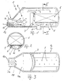
- the reformer shown in FIG. 1, generally designated 1, has a lateral gas supply 2, which is provided with insulation 3 on the inside and / or outside. This gas supply 2 opens into the mixing or reaction chamber designated 4.
- the vessel of the reformer 1 can be seen to be arranged horizontally, so that a catalyst, generally designated 6, arranged on a supporting arch 5 is provided on the side next to the mixing or reaction chamber.
- the catalyst 6 can for example consist of a bed of catalyst granules.
- a dividing wall 7 which tapers upwards and is curved in the form of a dam wall separates this region from one another.
- a gas-permeable supporting arch 5 is arranged in the bottom region of the reformer 1, designated 8, below the catalyst bed 6, the gas permeability being achieved through slots 9 in the example shown.
- the collection space 10 thus created for the treated gas is equipped with a discharge nozzle 11. This discharge nozzle 11 is arranged in the vicinity of the partition 7, such that the catalyst bed can be flowed through optimally.
- FIG. 3 shows an eccentric arrangement of the gas supply opening 3, which is provided here in the bottom area of the mixing or reaction chamber 4.
- Lances 12 for supplying the oxidizing agent are arranged within this gas supply 3, these lances 12 can be arranged concentrically around the full circumference within the gas supply 3 or, for example, as indicated in FIG. 1, in the lower semicircular arch.
- the supply 13 of a further gas can be provided there, the oxidizing agent distributor 14, for example, an annular chamber can also be equipped with a further admixture of steam or the like, which is not shown in more detail.
- oxidant supply lines 12a are here only partially indicated by dash-dotted lines.
- Swirl-generating elements 15 are also indicated here, which are only indicated symbolically and ensure optimum flow guidance in the reaction chamber 4a.
- the described exemplary embodiments of the invention can be modified in many ways without departing from the basic idea.
- a completely symmetrical design of the catalyst space 6 or the reaction chamber 4 can be provided, such that the gas supply 3 with the oxidant lances coming from below is introduced into this space symmetrically or in a similar arrangement to the discharge nozzle 11, this could be the cross-sectional shape of the reformer 1 be formed horizontally in the lower support area in order to make the inlet and outlet connections easier and the like. More.
Landscapes
- Chemical & Material Sciences (AREA)
- Chemical Kinetics & Catalysis (AREA)
- Organic Chemistry (AREA)
- Health & Medical Sciences (AREA)
- General Health & Medical Sciences (AREA)
- Engineering & Computer Science (AREA)
- Combustion & Propulsion (AREA)
- Inorganic Chemistry (AREA)
- Devices And Processes Conducted In The Presence Of Fluids And Solid Particles (AREA)
- Hydrogen, Water And Hydrids (AREA)
Description
- Die Erfindung richtet sich auf einen Reformer, insbesondere auf einen autothermen Sekundärreformer, mit einer Misch- bzw. Reaktionskammer für das Gas und das Oxidationsmittel sowie mit einem Katalysatorbett und einer Sammelkammer für das reformierte Gas.
- Reformer sind in unterschiedlichen Bauweisen bekannt, so zeigt die DE-A 2 841 127 eine weitverbreitete Konstruktion, bei der neben übereinander angeordneter Folge in einem Reformergefäß von oben nach unten ein aufwendiger Brenner, eine Misch- und Reaktionskammer, nachfolgend ein Katalysator und darunter eine Sammelkammer mit einem Traggewölbe für den Katalysator angeordnet sind. Eine günstigere Konstruktion zeigt die DE-A 1 542 539, da hier zentrisch von unten das zu behandelnde Gas zugeführt wird, womit sich insbesondere bei der Tragkonstruktion für den Katalysator Vorteile ergeben.
- Insgesamt nachteilig ist bei den bekannten Reformerkonstruktionen der vergleichsweise hohe Bauaufwand zur Stützung des Katalysatorbettes. Dabei ist nicht unwesentlich, daß hier sehr hohe Temperaturen zu beherrschen sind mit den damit verbundenen besonderen baulichen Maßnahmen, wie Innenauskleidungen, Isolierungen, Berücksichtigung der thermischen Dehnungen und dgl. mehr. Da die heißen zu reformierenden Gase insbesondere bei Sekundärreformern aus dem Primärreformer mit einer vergleichsweise niedrigen Ebene angeliefert werden, sind Zuspeisungen dieser Gase von oben in die Reformer mit den damit verbundenen Umlenkungen, Rohrkrümmern und dgl. sehr aufwendig, diesen Nachteil vermeidet die bereits genannte DE-A 1 542 539, da sie die heißen Gase von unten in den Reformer zuspeist, diese allerdings innerhalb des Reformers noch nach oben bis in den Kopfbereich der Misch- bzw. Reaktionskammer leitet.
- Aufgabe der Erfindung ist die Schaffung einer Lösung, mit der insbesondere der konstruktive und bauliche Aufwand derartiger Reformer verringert wird.
- Diese Aufgabe wird bei einem Reformer der eingangs bezeichneten Art dadurch gelöst, daß die Misch- bzw. Reaktionskammer und das Katalysatorbett in liegender Anordnung im wesentlichen horizontal nebeneinander vorgesehen sind.
- Die horizontale Anordnung von Mischkammer und Katalysatorbett bringt eine Fülle von Vorteilen mit sich. So kann ein liegender Reformer besonders einfach in der Zuspeisungsebene der heißen, zu reformierenden Gase angeordnet werden, in diesem Falle benötigt man Steigleitungen oder dgl. überhaupt nicht mehr. Ein wesentlicher Vorteil liegt aber auch darin, daß der Katalysator in jedem Falle in seiner Größe optimiert werden kann, da eine Verlängerung oder Verkürzung des zylindrischen Katalysatorraumes technisch keine Probleme aufwirft, was bei stehender Anordnung aber besondere Schwierigkeiten macht.
- Die horizontale Anordnung des Katalysators macht auch große Katalysatorkapazitäten möglich bei geringen Druckverlusten, da die Schütthöhe des Katalysatorbettes bei Kapazitätsvergrößerung gleichbleibt, hier liegt die Vergrößerung allein in der längeren Katalysatorbettgestaltung. Bei stehender Anordnung würde es bei gleichbleibendem Querschnitt und höher werdendem Katalysatorbett zu erheblichen Druckverlusten kommen. Eine horizontale Anordnung eines Katalysatorbettes ist für sich gesehen aus der US-A 2 788 265 bekannt. Hier wird aber lediglich die vertikale Bauweise durch eine horizontale ersetzt, ohne daß die Gestaltung der Mischkammer dieser neuen Bauweise Rechnung trägt, wie dies bei der vorliegenden Erfindung der Fall ist.
- In Ausgestaltung sieht die Erfindung vor, daß der Katalysatorraum eines im wesentlichen zylindrischen Reformerkörpers mit einem unteren, gasdurchlässigen Traggewölbe für eine Katalysatorschüttung ausgerüstet ist.
- Wie eingangs bereits ausgeführt, sind Traggewölbe für sich gesehen bekannt, allerdings in anderer Gestaltung und Anordnung als dies bei der vorliegenden Erfindung der Fall ist. Hier kann bei zylindrischer Katalysatorkammer in deren unteren Bodenbereich eine Abzugsrinne als gasdurchlässiges Gewölbe gemauert sein, über der viel mehr Katalysatormaterial anhäufbar ist, als dies bei den bekannten Konstruktionen der Fall wäre. Auch diese Maßnahme trägt dazu bei, sich bei der Wahl der Größe des Katalysators, keine Beschränkungen zu unterwerfen.
- Zweckmäßig ist es, die Trennwand zwischen Katalysatorraum und Reaktionskammer in Form einer Staumauer gewölbt auszubilden, wie dies die Erfindung ebenfalls vorsieht. Damit kann hinter dieser Staumauer eine große Menge an Katalysatormaterial angeordnet werden, selbst bei hohen Belastungen, insbesondere durch Wärme und dgl. hält eine derartige Konstruktion diesen Belastungen stand. Diesem Zweck dient auch eine weitere Ausgestaltung, die darin besteht, daß die Trennwand von unten nach oben gesehen sich verjüngend ausgebildet ist.
- Um dafür zu sorgen, daß die statische Druckdifferenz über die gesamte Katalysatorschüttung möglichst gleichmäßig ist, ist vorgesehen, daß der Abzugstutzen für das reformierte Gas dem Überströmbereich über die Trennmauer gegenüberliegend unterhalb des Traggewölbes angeordnet ist.
- Grundsätzlich sind symmetrische Anordnungen wegen der in der Regel einfacheren Bauweise erwünscht. Die liegende Bauweise des erfindungsgemäßen Reformers macht aber gerade auch asymmetrische Anordnungen von Bauteilen möglich, was beispielsweise zu Optimierungen der Strömungen der Gase führen kann.
- So sieht eine zweckmäßige Ausgestaltungsvariante der Erfindung vor, daß die Zuführöffnungen für das Gas und das Oxidationsmittel exzentrisch angeordnet sind, z.B. ohne daß hierauf die Erfindung beschränkt wäre, ist der Zuführstutzen aus der Mitte nach unten auf einer Stirnseite des Reformers verlagert.
- Zur Optimierung der Strömungsführung sieht die Erfindung darüber hinaus auch vor, daß die Oxidationsmitteizuführung aus einzelnen innerhalb der Gaszuführung angeordneten Zuführungslanzen gebildet ist, wobei es zweckmäßig sein kann, wenn am Auslaßende der Gaszuführung und/oder der Zuführlanzen für das Oxidationsmittel Düsen und/oder drallgebende Elemente vorgesehen sind.
- Mit diesen Gestaltungen ist es möglich, in der Misch- bzw. Reaktionskammer für optimale Mischungsverhältnisse zu sorgen.
- Darüber hinaus kann es zweckmäßig sein, neben Gas- und Oxidationsmittelzuführung eine Zuführung für weitere Gase vorzusehen, etwa für Erdgas, C02 oder dgl.
- Die Erfindung ist nachstehend anhand der Zeichnung beispielsweise näher erläutert. Diese zeigt in
- Fig. 1 den vereinfacht dargestellten Schnitt durch eine Ausführungsvariante des Reformers,
- Fig. 2 einen Schnitt durch einen Reformer gemäß Linie 11-11 in Fig. 1 sowie in
- Fig. 3 einen Querschnitt durch einen Reformer nach einer anderen Ausführungsvariante.
- Der in Fig. 1 dargestellte, allgemein mit 1 bezeichnete Reformer weist eine seitliche Gaszuführung 2 auf, welche mit einer Isolierung 3 innen und/oder außen versehen ist. Diese Gaszuführung 2 mündet in die mit 4 bezeichnete Misch- bzw. Reaktionskammer. Erkennbar ist das Gefäß des Reformers 1 liegend angeordnet, so daß seitlich neben der Misch- bzw. Reaktionskammer ein auf einem Stützgewölbe 5 angeordneter, allgemein mit 6 bezeichneter Katalysator vorgesehen ist.
- Der Katalysator 6 kann beispielsweise aus einer Schüttung aus Katalysatorgranulat bestehen. Um ein Einfallen in die Misch- bzw. Reaktionskammer 4 zu verhindern, trennt eine sich nach oben verjüngende und in Form einer Staumauer gewölbt gestaltete Trennwand 7 diesen Bereich voneinander.
- Wie sich insbesondere aus Fig. 2 ergibt, ist im mit 8 bezeichneten Bodenbereich des Reformers 1 unterhalb der Katalysatorschüttung 6 ein gasdurchlässiges Traggewölbe 5 angeordnet, wobei die Gasdurchlässigkeit im dargestellten Beispiel durch Schlitze 9 erreicht wird. Der so geschaffene Sammelraum 10 für das behandelte Gas ist mit einem Abzugsstutzen 11 ausgerüstet. Dieser Abzugsstutzen 11 ist in der Nähe der Trennwand 7 angeordnet, derart, daß das Katalysatorbett optimal durchströmbar ist.
- In Fig. 3 ist eine exzentrische Anordnung der Gaszuführöffnung 3 dargestellt, die hier im Bodenbereich der Misch- bzw. Reaktionskammer 4 vorgesehen ist. Innerhalb dieser Gaszuführung 3 sind Lanzen 12 zur Zuführung des Oxidationsmittels angeordnet, diese Lanzen 12 können dabei konzentrisch am vollen Umfang innerhalb der Gaszuführung 3 angeordnet sein oder z.B., wie in Fig. 1 angedeutet, im unteren Halbbogen. Zusätzlich kann die Zuführung 13 eines weiteren Gases dort vorgesehen sein, der Oxidationsmittelverteiler 14 z.B., eine Ringkammer kann dabei ebenfalls mit einer weiteren Zumischmöglichkeit von Dampf oder dgl. ausgerüstet sein, was nicht näher dargestellt ist.
- In Fig. 3 soll die völlig konzentrische Anordnung der Gaszuführöffnung 3a angedeutet sein, die Oxidationsmittelzuführungen 12a sind hier zum Teil nur strichpunktiert angegeben.
- Angedeutet sind hier auch drallgebende Elemente 15, die nur symbolisch angedeutet sind und für eine optimale Strömungsführung in der Reaktionskammer 4a sorgen.
- Natürlich sind die beschriebenen Ausführungsbeispiele der Erfindung noch in vielfacher Hinsicht abzuändern, ohne den Grundgedanken zu verlassen. So kann beispielsweise eine völlig symmetrische Bauweise des Katalysatorraumes 6 bzw. der Reaktionskammer 4 vorgesehen sein, derart, daß symmetrisch oder in ähnlicher Anordnung zum Abführstutzen 11 die Gaszuführung 3 mit den Oxidationsmittellanzen von unten kommend in diesen Raum eingeführt ist, hierfür könnte die Querschnittsform des Reformers 1 im unteren Auflagebereich horizontal ausgebildet sein, um die Zu- und Ableitstutzen einfacher gestalten zu können und dgl. mehr.
Claims (9)
dadurch gekennzeichnet,
daß die Misch- bzw. Reaktionskammer (4) und das Katalysatorbett (6) in liegender Anordnung im wesentlichen horizontal nebeneinander vorgesehen sind.
dadurch gekennzeichnet,
daß der Katalysatorraum (6) eines im wesentlichen zylindrischen Reformerkörpers mit einem unteren, gasdurchlässigen Traggewölbe (5) für eine Katalysatorschüttung ausgerüstet ist.
dadurch gekennzeichnet,
daß die Trennwand (7) zwischen Katalysator (6) und Reaktionskammer (4) in Form einer Staumauer gewölbt ausgebildet ist.
dadurch gekennzeichnet,
daß die Trennwand (7) von unten nach oben gesehen sich verjüngend ausgebildet ist.
dadurch gekennzeichnet,
daß der Abzugstutzen (11) für das reformierte Gas dem Überströmbereich über die Trennwand (7) gegenüberliegend unterhalb des Traggewölbes (5) angeordnet ist.
dadurch gekennzeichnet,
daß die Zuführöffnungen (3,12) für das Gas und das Oxidationsmittel exzentrisch angeordnet sind.
dadurch gekennzeichnet,
daß die Oxidationsmittelzuführung aus einzelnen innerhalb der Gaszuführung (3) angeordneten Zuführungslanzen (12) gebildet ist.
dadurch gekennzeichnet,
daß am Auslaßende der Gaszuführung (3a) und/oder der Zuführlanzen für das Oxidationsmittel Düsen und/oder drallgebende Elemente (15) vorgesehen sind.
dadurch gekennzeichnet,
daß neben Gas- und Oxidationsmittelzuführung (12) eine Zuführung (13) für weitere Gase vorgesehen ist.
Applications Claiming Priority (2)
| Application Number | Priority Date | Filing Date | Title |
|---|---|---|---|
| DE19873735192 DE3735192A1 (de) | 1987-10-17 | 1987-10-17 | Reformer |
| DE3735192 | 1987-10-17 |
Publications (2)
| Publication Number | Publication Date |
|---|---|
| EP0312754A1 EP0312754A1 (de) | 1989-04-26 |
| EP0312754B1 true EP0312754B1 (de) | 1990-12-05 |
Family
ID=6338538
Family Applications (1)
| Application Number | Title | Priority Date | Filing Date |
|---|---|---|---|
| EP88114663A Expired - Lifetime EP0312754B1 (de) | 1987-10-17 | 1988-09-08 | Reformer |
Country Status (3)
| Country | Link |
|---|---|
| EP (1) | EP0312754B1 (de) |
| DE (2) | DE3735192A1 (de) |
| DK (1) | DK571288A (de) |
Families Citing this family (3)
| Publication number | Priority date | Publication date | Assignee | Title |
|---|---|---|---|---|
| CA2384764A1 (en) | 1999-10-05 | 2001-04-12 | Ballard Power Systems Inc. | Autothermal reformer |
| DE10021815A1 (de) * | 2000-05-04 | 2001-11-08 | Daimler Chrysler Ag | Vorrichtung zum dosierten Einbringen von Edukten in einen Reaktor |
| DE10247764A1 (de) * | 2002-10-14 | 2004-04-22 | Robert Bosch Gmbh | Zerstäuberdüse |
Family Cites Families (5)
| Publication number | Priority date | Publication date | Assignee | Title |
|---|---|---|---|---|
| US2788265A (en) * | 1953-12-17 | 1957-04-09 | Phillips Petroleum Co | Reformer for ammonia synthesis gas |
| DE1542539A1 (de) * | 1966-10-25 | 1970-09-24 | Uhde Gmbh Friedrich | Axialdurchstroemter Reaktionsturm |
| US4054418A (en) * | 1975-11-10 | 1977-10-18 | E. I. Du Pont De Nemours And Company | Catalytic abatement system |
| JPS52129705A (en) * | 1976-04-24 | 1977-10-31 | Nissan Motor Co Ltd | Methanol-reforming apparatus |
| US4246235A (en) * | 1978-03-13 | 1981-01-20 | Engelhard Minerals & Chemicals Corporation | Horizontal flow catalytic reactor |
-
1987
- 1987-10-17 DE DE19873735192 patent/DE3735192A1/de not_active Withdrawn
-
1988
- 1988-09-08 DE DE8888114663T patent/DE3861237D1/de not_active Expired - Fee Related
- 1988-09-08 EP EP88114663A patent/EP0312754B1/de not_active Expired - Lifetime
- 1988-10-13 DK DK571288A patent/DK571288A/da not_active Application Discontinuation
Also Published As
| Publication number | Publication date |
|---|---|
| DE3735192A1 (de) | 1989-05-03 |
| DE3861237D1 (en) | 1991-01-17 |
| EP0312754A1 (de) | 1989-04-26 |
| DK571288A (da) | 1989-04-18 |
| DK571288D0 (da) | 1988-10-13 |
Similar Documents
| Publication | Publication Date | Title |
|---|---|---|
| DE2222562B2 (de) | Reaktionsturm mit mehreren nacheinander radial durchströmten ringförmigen Reaktionskammern | |
| DE2647486B2 (de) | Hydrozyklon | |
| DE1960721U (de) | Austauschkolonne fuer zwei stroemungsmittel. | |
| DE19912318A1 (de) | Plattenreaktor | |
| EP0312757B1 (de) | Reformer, insbesondere autothermer Sekundärreformer | |
| EP0312754B1 (de) | Reformer | |
| DE3032281A1 (de) | Reaktionsgefaess | |
| DE10205660B4 (de) | Verfarhen und Vorrichtung zur kontinuierlichen Stahlherstellung unter Einsatz von metallischen Einsatzmaterial | |
| DE3125320C1 (de) | Schachtofen zum Brennen und Sintern von stueckigem Gut mit Innenbrenner | |
| DE2541991A1 (de) | Keramischer brenner | |
| DE1035297B (de) | Vorrichtung zur Durchfuehrung von Kohlenwasserstoff-umwandlungsverfahren | |
| EP0235367B1 (de) | Vorrichtung zum Einsetzen in einem Verfahren zur Erzeugung von Produktgas mit Wasserstoff- und Kohlenoxidgehalten | |
| DE2337958C3 (de) | Kontaktkessel für die katalytische Umsetzung von SO2ZuSO3 | |
| EP0473870B1 (de) | Reformer, insbesondere autothermer Sekundärreformer | |
| EP0360981B1 (de) | Reaktor zur Durchführung katalytischer Gasreaktionen mit einem druckfesten Mantel und je einem Kugelboden am stirnseitigen Aussenrand | |
| WO1988001983A2 (en) | Reformer for catalytic cracking of gaseous hydrocarbons | |
| DE10211942A1 (de) | Verfahren zur Steuerung einer Kohlenmonoxidkonzentration aus einem Reaktor für selektive Oxidation während eines Abschaltens unter Verwendung einer gestuften Luftzuführung über mehrere Durchlässe | |
| AT397569B (de) | Brenner | |
| AT310649B (de) | Verteilungssystem für strömende Medien | |
| DE2333519C3 (de) | Schachtofen zur kontinuierlichen Direktreduktion von stückigem Eisenerz | |
| DE3807333A1 (de) | Einrichtung zum entleeren metallurgischer behaelter | |
| DE3733349C2 (de) | ||
| DE764383C (de) | Kammer- oder Retortenofen zur Erzeugung von Gas und Koks | |
| EP0566945B1 (de) | Vorrichtung zum Erwärmen von Wasser, insb. Warmwasserheizkessel | |
| DE2322393C3 (de) | Roststein für Tragroste zur Auflagerung der Füllkörper in Wasch- und Reaktionstürmen |
Legal Events
| Date | Code | Title | Description |
|---|---|---|---|
| PUAI | Public reference made under article 153(3) epc to a published international application that has entered the european phase |
Free format text: ORIGINAL CODE: 0009012 |
|
| AK | Designated contracting states |
Kind code of ref document: A1 Designated state(s): BE DE FR GB IT NL |
|
| 17P | Request for examination filed |
Effective date: 19890330 |
|
| 17Q | First examination report despatched |
Effective date: 19900104 |
|
| GRAA | (expected) grant |
Free format text: ORIGINAL CODE: 0009210 |
|
| AK | Designated contracting states |
Kind code of ref document: B1 Designated state(s): BE DE FR GB IT NL |
|
| REF | Corresponds to: |
Ref document number: 3861237 Country of ref document: DE Date of ref document: 19910117 |
|
| ET | Fr: translation filed | ||
| ITF | It: translation for a ep patent filed | ||
| GBT | Gb: translation of ep patent filed (gb section 77(6)(a)/1977) | ||
| PLBE | No opposition filed within time limit |
Free format text: ORIGINAL CODE: 0009261 |
|
| STAA | Information on the status of an ep patent application or granted ep patent |
Free format text: STATUS: NO OPPOSITION FILED WITHIN TIME LIMIT |
|
| 26N | No opposition filed | ||
| PGFP | Annual fee paid to national office [announced via postgrant information from national office to epo] |
Ref country code: FR Payment date: 19920826 Year of fee payment: 5 |
|
| PGFP | Annual fee paid to national office [announced via postgrant information from national office to epo] |
Ref country code: GB Payment date: 19920827 Year of fee payment: 5 Ref country code: BE Payment date: 19920827 Year of fee payment: 5 |
|
| PGFP | Annual fee paid to national office [announced via postgrant information from national office to epo] |
Ref country code: DE Payment date: 19920901 Year of fee payment: 5 |
|
| ITTA | It: last paid annual fee | ||
| PGFP | Annual fee paid to national office [announced via postgrant information from national office to epo] |
Ref country code: NL Payment date: 19920930 Year of fee payment: 5 |
|
| PG25 | Lapsed in a contracting state [announced via postgrant information from national office to epo] |
Ref country code: GB Effective date: 19930908 |
|
| PG25 | Lapsed in a contracting state [announced via postgrant information from national office to epo] |
Ref country code: BE Effective date: 19930930 |
|
| BERE | Be: lapsed |
Owner name: UHDE G.M.B.H. Effective date: 19930930 |
|
| PG25 | Lapsed in a contracting state [announced via postgrant information from national office to epo] |
Ref country code: NL Effective date: 19940401 |
|
| GBPC | Gb: european patent ceased through non-payment of renewal fee |
Effective date: 19930908 |
|
| NLV4 | Nl: lapsed or anulled due to non-payment of the annual fee | ||
| PG25 | Lapsed in a contracting state [announced via postgrant information from national office to epo] |
Ref country code: FR Free format text: LAPSE BECAUSE OF NON-PAYMENT OF DUE FEES Effective date: 19940531 |
|
| PG25 | Lapsed in a contracting state [announced via postgrant information from national office to epo] |
Ref country code: DE Effective date: 19940601 |
|
| REG | Reference to a national code |
Ref country code: FR Ref legal event code: ST |
|
| PG25 | Lapsed in a contracting state [announced via postgrant information from national office to epo] |
Ref country code: IT Free format text: LAPSE BECAUSE OF NON-PAYMENT OF DUE FEES;WARNING: LAPSES OF ITALIAN PATENTS WITH EFFECTIVE DATE BEFORE 2007 MAY HAVE OCCURRED AT ANY TIME BEFORE 2007. THE CORRECT EFFECTIVE DATE MAY BE DIFFERENT FROM THE ONE RECORDED. Effective date: 20050908 |