EP0312870A2 - Couvercle pour château contenant des matériaux radioactifs - Google Patents
Couvercle pour château contenant des matériaux radioactifs Download PDFInfo
- Publication number
- EP0312870A2 EP0312870A2 EP88116756A EP88116756A EP0312870A2 EP 0312870 A2 EP0312870 A2 EP 0312870A2 EP 88116756 A EP88116756 A EP 88116756A EP 88116756 A EP88116756 A EP 88116756A EP 0312870 A2 EP0312870 A2 EP 0312870A2
- Authority
- EP
- European Patent Office
- Prior art keywords
- lid
- opening
- outer lid
- cask
- improved closure
- Prior art date
- Legal status (The legal status is an assumption and is not a legal conclusion. Google has not performed a legal analysis and makes no representation as to the accuracy of the status listed.)
- Withdrawn
Links
Images





Classifications
-
- G—PHYSICS
- G21—NUCLEAR PHYSICS; NUCLEAR ENGINEERING
- G21F—PROTECTION AGAINST X-RADIATION, GAMMA RADIATION, CORPUSCULAR RADIATION OR PARTICLE BOMBARDMENT; TREATING RADIOACTIVELY CONTAMINATED MATERIAL; DECONTAMINATION ARRANGEMENTS THEREFOR
- G21F5/00—Transportable or portable shielded containers
-
- G—PHYSICS
- G21—NUCLEAR PHYSICS; NUCLEAR ENGINEERING
- G21F—PROTECTION AGAINST X-RADIATION, GAMMA RADIATION, CORPUSCULAR RADIATION OR PARTICLE BOMBARDMENT; TREATING RADIOACTIVELY CONTAMINATED MATERIAL; DECONTAMINATION ARRANGEMENTS THEREFOR
- G21F5/00—Transportable or portable shielded containers
- G21F5/06—Details of, or accessories to, the containers
- G21F5/10—Heat-removal systems, e.g. using circulating fluid or cooling fins
-
- G—PHYSICS
- G21—NUCLEAR PHYSICS; NUCLEAR ENGINEERING
- G21F—PROTECTION AGAINST X-RADIATION, GAMMA RADIATION, CORPUSCULAR RADIATION OR PARTICLE BOMBARDMENT; TREATING RADIOACTIVELY CONTAMINATED MATERIAL; DECONTAMINATION ARRANGEMENTS THEREFOR
- G21F5/00—Transportable or portable shielded containers
- G21F5/06—Details of, or accessories to, the containers
- G21F5/12—Closures for containers; Sealing arrangements
Definitions
- This invention generally relates to casks for transporting radioactive materials, and is specifically concerned with an improved double-lidded closure capable of closing and sealing such a cask without the application of rubbing or scraping forces on the gasket seal between the cask and the closure.
- Casks for transporting radioactive materials such as the waste products produced by nuclear power facilities are known in the prior art.
- the purpose of such casks is to ship radioactive wastes in as safe a manner as possible.
- Such casks may be used, for example, to ship high-level vitrified waste canisters to a permanent waste isolation site or fuel rods to a reprocessing facility.
- relatively few of such transportation casks have been manufactured and used since most of the spent fuel and other wastes generated by nuclear power plants are being stored at the reactor facilities themselves. However, the availability of such on-site storage space is steadily diminishing as an increasing amount of fuel assemblies and other wastes are loaded into the spent-fuel pools of these facilities. Additionally, the U.S.
- the primary closure for a typical prior-art transportation cask is generally formed from a circular lid which is attached over the open end of the cask by twenty-four bolts.
- the threaded ends of these bolts are received in twenty-four bores uniformly provided around the circumference of the lid near the outer edge thereof.
- a bolt ring welded around the open end of the cask includes twenty-four threaded bores which are registerable with the ends of the bolts when they are extended completely through the closure lid.
- the lid is circumscribed by a gasket or o-ring of resilient material. In operation, the twenty-four closure bolts are inserted into the bolt bores around the lid.
- the lid is then hoisted over the bolt ring of the casks, and the threaded ends of the bolts extending through the lid bores are carefully aligned with the threaded bores in the ring.
- the bolts are then screwed into the threaded bores of the bolt ring in order to effect the closure.
- the twenty-four bolts must be tightened in accordance with an intricate torquing pattern, wherein bolts oppositely disposed from one another across the cask lid are simultaneously tightened.
- a fourth significant drawback to this prior art closure design is the fact that significant wiping and scraping forces are often applied to the gasket as the bolts in the lid are being azimuthly aligned with the threaded bolt holes in the bolt ring. Such scraping or wiping forces can seriously jeopardize the sealing ability of the gasket, and will, at the very least, accelerate its wear-out.
- the minimum diameter of the bolt ring is smaller than the diameter of the mouth of the opening it circumscribes. Consequently, a bolt ring often provides an unwanted lip or flange around the opening that interferes with the loading and unloading of the cask.
- a closure for a cask assembly which corrects all of the aforementioned drawbacks associated with the prior art.
- a closure should avoid the application of scraping or wiping forces to the gasket seal in order to prevent the premature wear-out of the gasket.
- a closure should be rapidly attachable to the open end of the casks so as to minimize the exposure of the personnel implementing the closing of the casks to potentially harmful radiation, and devoid of any unwanted lips or flanges that interfere with the loading and unloading of the cask.
- the closure be at least as strong as the cask wall themselves, and capable of maintaining an effective seal around the casks in the event of an accident which applies substantial shock forces to the casks.
- the invention is an improved closure for covering and sealing a ledge-surrounded opening in a cask of the type used to contain radioactive material that solves all the aforementioned drawbacks.
- the improved closure comprises an inner lid having an outer edge that is seatable over the ledge of the opening, and an outer lid rotatably connected to the inner lid which is securable around the cask opening when the outer lid is rotated.
- the improved closure preferably includes a breech-lock mechanism for securing the outer lid to the opening which is formed by a first set of flanges uniformly spaced around the outer lid that are insertable through the spaces between the first set of flanges and movable therebehind when the outer lid is rotated.
- complementary screw threads may be provided between the outer lid and the cask opening.
- the outer edge of the inner lid includes a gasket that engages the ledge circumscribing the cask opening when the lid is secured therearound.
- the improved closure may include a means for rotatably connecting the inner and outer lids which is formed by a plurality of suspension pin assemblies.
- These suspension pin assemblies may include brackets which are mounted uniformly around the circumference of the outer lid, and pins which are captured and slidably movable within a groove which extends circumferentially around the edge of the inner lid.
- the improved closure may further include a means for depressing the outer edge of the inner lid into sealing engagement against the ledge that circumscribes the opening of the cask.
- This depressing means may take the form of a plurality of bolts engaged within threaded bores which extend completely through the outer lid. Each of these bolts may be screwed into engagement against the top surface of the inner lid, thereby depressing the edge of the inner lid into tight engagement around the ledge which circumscribes the cask opening.
- the improved closure may include a lock means for preventing the outer lid from rotatably moving relative to the inner lid.
- this lock means takes the form of the bracket having a leg which is insertable in the space between the flanges of both the inner and the outer lid when the outer lid is secured to the cask opening.
- the locking bracket is detachably mountable onto the outer lid of the improved closure.
- the novel cask assembly 1 that the invention directly applies to is particularly useful in carrying radioactive materials of different activities aboard a vehicle such as a tractor-trailer.
- the cask assembly 1 is typically mounted within a novel biaxial restraint cradle 3, which in turn is secured onto the trailer of a tractor-trailer (not shown).
- the cask assembly itself has a cylindrical body 5 which is circumscribed on either end by toroidal impact limiters 7a, and 7b.
- Each of these impact limiters 7a, 7b is a donut-shaped shell of yieldable aluminum which is approximately one-half of an inch thick.
- Each of the toroidal impact limiters 7a, 7b is mounted around its respective end of the cylindrical body 5 by means of a support ring assembly 8a, 8b which in turn is secured to the cylindrical body 5 by a plurality of bolts 9 (shown in Figures 3 and 5).
- a support ring assembly 8a, 8b Disposed between the impact limiters 7a, 7b are two pairs of opposing trunnions 11a, 11b and 11c, 11d.
- the two pairs of trunnions are disposed 180 degrees apart around the cylindrical body 5 of the cask assembly 1, and are receivable within two pairs of turnbuckle assemblies 12a, 12b, and 12c, 12d (of which only 12a and 12b are visible) that form part of the novel cradle 3.
- the cylindrical body 5 is capped by a closure 13 at one end, and an end plate assembly 15 (shown in Figure 3) at the other end.
- the cylindrical body 5 of the cask assembly 1 is generally formed by an outer container 18 which is surrounded by a thermal protection shell 20 on its exterior, and which contains in its interior one of two different shield inserts 22 or 23, depending upon the activity and type of radiation emitted by the material to be transported.
- shield inserts 22 and 23 While only two specific types of shield inserts 22 and 23 are specifically disclosed herein, it should be noted that the inserts 22 and 23 are merely exemplary, and that the cask assembly 1 may in fact be used with any number of different types of shield inserts formed of different shielding materials and of different wall thicknesses for handling radioactive material within a broad range of activity and radiation type.
- the thermal protection shell 20 which circumscribes the outer container 18 of the cask assembly 1 is formed from a pair of semi-cylindrical shell sections 24a, 24b which are rigidly interconnectable into thermal contact with one another.
- Each of the shell sections 24a, 24b includes a pair of cut-outs 26 (shown in Figure 3) for admitting the trunnions 11a, 11b 11c, and 11d.
- Each of the shell sections 24a, 24b is formed from a metal having a thermal coefficient of expansion which is greater than that of the metal that forms the walls of the outer container 18, and which is at least as heat-conductive as the metal which forms the walls 54 of the outer container 18.
- the shell sections 24a, 24b are preferably formed from aluminum or magnesium or an alloy of either or both of these metals.
- the coefficient of thermal expansion of these metals is approximately twice that of the thermal coefficient expansion of steel.
- the high coefficient of thermal conductivity of each such metal insures that the thermal protection shell 20 will not significantly obstruct the conduction of decay heat conducted through the walls of the outer container 18 which is generated by the radioactive material held within the cask assembly 1.
- the diameter of the outer container 18 is between forty and sixty inches (1.02-1.52 m)
- a wall thickness of approximately one-half of an inch (12.7 mm) is preferred for both of the shell sections 24a, 24b.
- Such a wall thickness renders the thermal protection shell 20, as a whole, thin enough to be conveniently retrofitted over many existing transportation casks without significantly adding to the weight thereof, yet thick enough to maintain the structural integrity needed to expand away from the outer walls of the outer container when exposed to a source of intense thermal radiation, such as a fire.
- the preferred thickness of one-half of an inch (12.7 mm) provides enough mass to give the entire thermal protection shell 20 a significant latent heat of fusion, which will provide still more thermal. protection through oblation should the cask 1 be exposed to intense heat.
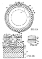
- top and bottom connecting assemblies 28, 29 are used to rigidly interconnect the two semi-cylindrical shell sections 24a, 24b. Since each of the connecting assemblies 28, 29 are identical in structure, a description will be made only of the top connecting assembly 28 circled in Figure 2A.
- This connecting assembly 28 is formed from a pair of opposing semicircular lugs 30a and 30b which are integrally formed along the edges of the shell sections 24a and 24b respectively.
- These lugs 30a, 30b include mutually alignable bore holes 31a and 31b for receiving a connecting bolt 32.
- the threaded end 33 of the bolt 32 is engaged to a tension nut 34 as shown in Figure 2B.
- the distance between the two lugs 30a, 30b (and hence the distance between the edges of the shell sections 24a, 24b) is largely determined by the extent of which the end 33 and the bolt 32 is threaded through the tension nut 34.
- a lock washer 35 is disposed between the tension nut 34 and the lug 30a to prevent the nut 34 from becoming inadvertently loosened.
- a pair of lock nuts 36a, 36b are threadedly engaged near the center portion of the connecting bolt 32 between the two lugs 30a and 30b. These lock nuts provide two functions. First, when properly adjusted, they prevent the tension nut 34 from applying excess tensile forces between the two shell sections 24a and 24b which might interfere with their expansion away from the outer container 18 in the event the cask assembly is exposed to a fire or other source of intense heat.
- the nuts 36a, 36b eliminate all slack or play between the lugs 30a, 30b, thus insuring that the connecting assembly 28 rigidly interconnects the two shield sections 30a, 30b.
- lock washers 37a, 37b are disposed between the lock nuts 36a and 36b and their respective lugs 30a and 30b to prevent any inadvertent loosening from occurring.
- An overlap 40 is provided between the edges of the two shell sections 24a and 24b to establish ample thermal contact and hence thermal conductivity between these shell sections.
- the overlap 40 is formed from an outer flange 42 and recess 44 provided along the edge of shell section 24a which interfits with a complementary outer flange 46 and recess 48 provided along the opposing edge of shield section 24b.
- the actual length of the overlap 40 will vary depending upon the distance between the two lugs 30a and 30b as adjusted by the bolt 32, tension nut 34, and lock nuts 36a and 36b.
- the two sections 24a, 24b of the thermal protection shell 20 are installed over the cask assembly 1 by aligning the various cutouts 26a, 26b, 26c, and 26d with the corresponding trunnions of 11a, 11b, 11c, and 11d which project from the cylindrical body 5, and placing the sections 24a, 24b together so that the lugs 30a and 30b of each of the connecting assemblies 28, 29 are in alignment with one another and the flanges and recesses 42, 44, and 48, 48 of each overlaps 40 are interfitted.
- the bolt 32, tension nut 35, lock nuts 36a, 36b, and lock washers 35, 37a, and 37b are installed in their proper positions with respect to the lugs 30a, 30b of each of the connecting assemblies 28, 29.
- the tension nut 34 is then screwed over the threaded end 33 of connecting bolt 32 until the interior surface of each of the shell sections 24a and 24b is pulled into intimate thermal contact with the outside wall 54 of the outer container 18.
- the tension nut 34 of each of the connecting assemblies 28, 29 is initially torqued to a selected maximum on the threaded shaft of the bolt 32 until the nut 34 imparts a significant tensile force between the two lugs 30a and 30b.
- each of the nuts 34 is relaxed enough to prevent these tensile clamping forces from interfering with the expansion of the thermal protection shell 20 in the event of a fire, yet not so much as to cause the surfaces of the shell 20 and the outer container from becoming disengaged with one another.
- the shell 20 may assume the form of a tubular sleeve which may be, in effect, heat shrunk into contact over the container 18.
- This alternative method of installation comprises the steps of removing the impact limiters 7a, 7b heating the shell to a temperature sufficient to radially expand it, sliding it over the wall 54 of the outer container 18, allowing it to cool and contract into intimate thermal contact with the wall 54, and reinstalling the impact limiters 7a, 7b.
- Figure 2C illustrates the typical gap condition between the inner surface of the thermal protection shell 20 and the outer surface of the outer container 18. Under ambient conditions, these two opposing surfaces are either in direct contact with one another, or separated by only a tiny gap 50 which may be as much as one mil (0.0254 mm). Such a one mil (0.0254 mm) separation at various points around the cask assembly 1 does not significantly interfere with the conduction of heat between the wall 54 of the outer cask 18, and the thermal protection shell 20.
- the cask assembly 1 when the cask assembly 1 is exposed to a source of intense thermal radiation such as a fire, the substantially higher thermal coefficient of expansion of the aluminum or magnesium forming the shell 20 will cause it to expand radially away from the outer surface of the outer container 18, leaving an air gap 53 (shown in phantom) between the two surfaces.
- the thermal protection shield 20 is formed from a metal having good heat conductive properties, this differential thermal expansion is substantially uniform throughout the entire circumference of the shield 20, which means that the resulting insulatory air gap 53 is likewise substantially uniform.
- this gap exceeds approximately two and one-half mils (0.0635 mm) the primary mode of heat transfer switches from conductive and convective to radioactive.
- the three mil (0.0762 mm) gap provides a substantial thermal resistor between the fire or other source of intense infrared radiation in the outer container 18 of the cask 1.
- the side walls of the outer container 18 of the improved cask 1 are a laminate formed from the previously mentioned outer wall 54, an inner wall 56, and a center layer 58 of shielding material.
- the outer wall 54 is formed from low alloy steel approximately one-fourth of an inch (6.4 mm) thick. Such steel is economical, easy to manufacture, and a reasonably good conductor of heat. In the alternative, stainless steel may be used in lieu of low alloy steel. While the use of stainless steel would be more expensive, it provides the additional advantage of corrosion-resistance.
- the inner wall 56 is preferably also formed from low alloy steel. However, the inner wall 56 is made two inches thick (50.8 mm) in order to provide ample structural rigidity and strength to the outer container 18.
- Boro-Silicone Disposed between the outer wall 54 and the inner wall 56 is a layer of Boro-Silicone.
- This material advantageously absorbs neutrons from neutron-emitting radioactive materials (such as transuranic elements), and further is a relatively good conductor of heat. It is a rubbery material easily cast, and may be melted and poured between the inner and outer walls 54, 56 of the outer container 18 during its manufacture.
- Boro-Silicone is available from Reactor Experiments, Inc.
- the bottom of the outer container 18 is formed by an end plate assembly 15 that includes an outer plate 60, an inner plate 62, and a layer of center shielding material 64.
- the outer plate 60 is again formed from a low alloy steel approximately one-fourth inch (6.4 mm) thick.
- the inner plate 62 like the inner wall 56, is again formed from a layer of low alloy steel approximately two inches (50.8 mm) thick.
- the center shielding material 64 is again preferably Boro-Silicone for all the reasons mentioned in connections with the center shielding material 58 of the side walls of the container 18.
- the low alloy steel inner plate 62 is joined around the bottom edge of the inner wall 56a 360° via weld joint 66.
- the top of the outer container 28 includes a forged ring of low alloy steel 68.
- This ring is preferably four inches thick (101.6 mm) throughout its length, and is integrally connected to the inner wall 56 of the container 18 by a 360° weld joint 69.
- the upper edge of the ring 68 is either threaded or stepped to accommodate one of the two types of improve closures 115b and 117b, as will be explained in detail hereinafter.
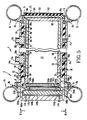
- the cask assembly 1 is formed from the outer container 18 and shell 20 in combination with one of two different shield inserts 22 (illustrated in Figure 5).
- Each of the shield inserts 22, 23 is formed from an outer cylindrical wall 72 which is preferably one inch (25.4 mm) thick and a cylindrical inner wall 74 which is approximately one-fourth of an inch (6.4 mm) thick. Both walls are formed from AISI type 304 stainless steel. The corrosion resistance of stainless steel prevents the outer dimensions of the outer wall 74 from becoming distorted as a result of rust, which in turn helps advantageously to maintain a relatively tight, slack-free fit between the shield inserts 22, 23 and the interior of the outer container 18.
- Each of the shield inserts 22 and 23 includes a layer of shielding material 76 between their respective outer and inner walls 72, 74.
- this shielding material is formed from a plurality of ring-like sections 78a, 78b, and 78c of either depleted uranium or tungsten. These materials have excellent gamma shielding properties, and are particularly well adapted to contain and shield radioactive material emitting high intensity gamma radiation.
- a single tubular layer of depleted uranium or tungsten could be used in lieu of the three stacked ring-like sections 78a, 78b, and 78c.
- the use of stacked ring-like sections is preferred due to the difficulty of fabricating and machining these metals.
- shield insert 23 a layer of poured lead 80 is used as the shielding material 76. While lead is not as effective a gamma shield as depleted uranium, it is a better material to use in connection with high-neutron emitting materials, such as the transuranic elements. Such high neutron emitters can induce secondary neutron emission when depleted uranium is used as a shielding material.
- lead is a preferred shielding material when high-neutron emitting materials are to be transported. It should be noted that the radius of the interior of the shield inserts 22 and 23 will be custom dimensioned with a particular type of waste to be transported so that the inner wall 74 of the insert comes as close as possible into contact with the radioactive material contained therein. The Applicant has noted that fulfillment of the foregoing criteria provides the most effective shielding configuration per weight of shielding material.
- the thickness and type of shielding material 76 will be adjusted in accordance with the activity of the material contained within the shield insert 22, 23 so that the surface radiation of the cask assembly 1 never exceeds 200 mr. The fulfillment of these two criteria maximizes the capacity of the cask assembly 1 to carry radioactive materials while simultaneously minimizing the weight of the cask.
- FIGS 4A and 4B illustrate the vent purge, and drain assembly 90 of the outer container 18.
- This assembly 90 includes a threaded drain pipe 92 for receiving a drain plug 94.
- the inner end 96 of the drain plug 94 is conically shaped and seatable in sealing engagement with a complementary valve seat 97 located at the inner end of the pipe 92.
- Wrench flats 98 integrally formed at the outer end of the drain plug 94 allow the plug 94 to be easily grasped and rotated into or out of sealing engagement with the valve seat 97.
- a vent pipe 100 is obliquely disposed in fluid communication with the end of the drain pipe 92.
- a threaded vent plug 102 is engageable into and out of the vent pipe 100.
- a screw head 103 is provided at the outer end of the vent plug 102 to facilitate the removal or insertion of the threaded plug 102 into the threaded interior of the vent pipe 100.
- a drain tube 104 is fluidly connected at its upper end to the bottom of the valve seat 97 by way of a fitting 106.
- the drain tube 104 is formed from stainless steel, and is housed in a side groove 108 provided along the inner surface of the wall 56 of the outer container 18. As is most easily seen in Figure 4B, the lower open end 109 of the drain tube 104 is disposed in a bottom groove 110 which extends through the shallowly conical floor 112 of the outer container 18.
- vent, purge, and drain assembly may be used to vent the interior of the outer container 18 by removing the vent plug 102 from the vent pipe 100, screwing an appropriate fitting (not shown) into the threaded vent pipe 100, in order to channel gases to a mass spectometer, and screwing the conical end 96 of the drain plug 94 out of sealing engagement with the valve seat 97. If drainage is desired, the drain plug 94 is removed.
- a suction pump is connected to the drain pipe 92 in order to pull out, via drain tube 104, any liquids which may have collected in the bottom groove 110 of the conical floor 112 of the outer container 18. Gas purging is preferably accomplished after draining by removing the vent plug 102, and connecting a source of inert gas to the drain pipe 92.
- the partial vacuum within the container 18 that was created by the suction pump encourages inert gas to flow down through the drain tube 104.
- the interior of the drain plug 98 may be provided with one or more rupture discs to provide for emergency pressure relief in the event that the cask assembly 1 is exposed to a source of intense thermal radiation, such as a fire, over a protracted period of time.
- the improved closures 13 used in connection with the cask assembly 1 may be either screw-type double-lidded closures 115a, 115b (illustrated in Figure 3), or breech-lock double-lidded closures 117a, 117b (illustrated in Figure 5).
- each of the screw-type closures 115a, 115b includes an outer lid 120a, 120b, and an inner lid 122a, 122b.
- the inner lid 122a, 122b in turn includes an outer edge 124a, 124b which is seatable over a ledge 126a, 126b provided around the opening 128a, 128b of the shield insert 22 or the outer container 18 respectively.
- a gasket 130a, 130b circumscribes the outer edge 124a, 124b of each of the inner lids 122a, 122b of the two closures 115a, 115b.
- these gaskets 130a, 130b are formed of Viton because of its excellent sealing characteristics and relatively high temperature limit (392°F) (200°C) compared to other elastomers.
- the gasket 130a, 130b of each of the inner lids 122a and 122b is preferably received and held within an annular recess (not shown) that circumscribes the outer edge 124a, 124b of each lid.
- Each of these gaskets 130a, 130b is capable of effecting a fluid-tight 360 degree seal between the outer edge 124a, 124b of each of the inner lids 122a, 122b and the ledges 126a, 126b.
- the opening 128b of the container 18 is at least as wide as the interior of the container 18 at all points.
- Each of the outer lids 120a, 120b of the screw-type closures 115a, 115b includes a threaded outer edge 134a, 134b which is engageable within a threaded inner edge 136a, 136b that circumscribes the openings 128a, 128b of the shield insert 22 and the outer container 18 respectively.
- Swivel hooks 137a, 137b may be detachably mounted to the centers of the outer lids 120a, 120b to facilitate the closure operation.
- both of the outer lids 120a, 120b of the screw-type closures 115a, 115b includes a plurality of sealing bolts 138a-h, 139a-h, threadedly engaged in bores extending all the way through the outer lids 120a, 120b for a purpose which will become apparent shortly.
- inner lid 122a is lowered over ledge 126a of the shield insert 22 so that the gasket 130 is disposed between the outer edge 124a of the inner lid 122a and ledge 126a.
- the detachably mountable swivel hook 137 is mounted onto the center of the outer lid 120a.
- the outer lid 120a is then hoisted over the threaded inner edge 136a of the shield insert 22.
- the threaded outer edge 134a of the outer lid 120a is then screwed into the threaded inner edge 136a to the maximum extent possible.
- the axial length of the screw threads 134a and 136a are dimensioned so that, after the outer lid 120a is screwed into the opening 128a to the maximum extent possible, a gap will exist between the inner surface of the outer lid 120a and the outer surface of the inner lid 122a.
- the outer screw-type closure 115b is mounted over the opening 128b of the outer container 18 in precisely the same fashion as described with respect to the opening 128a of the shield insert 22.
- the breech-lock double-lidded closure 117a, 117b also includes a pair of outer lids 140a, 140b which overlies a pair of inner lids 142a, 142b respectively.
- Each of the inner lids 142a, 142b likewise includes an outer edge 144a, 144b which seats over a ledge 146a, 146b that circumscribes the opening 148a, 148b of the shielding insert 23 and outer container 18, respectively.
- Each of the outer edges 144a, 144b is circumscribed by a gasket 150a, 150b for effecting a seal between the edges 144a, 144b and their respective ledges 146a, 146b.
- opening 148b is at least as wide as the interior of the outer container 18.
- the structure of the breech-lock double-lidded closures 117a, 117b has been essentially identical with the previously described structure of the screw-type double-lidded closures 115a, 115b.
- the outer edges 154a, 154b of each of the outer lids 140a, 140b are circumscribed by a plurality of uniformly spaced arcuate notches 156a, 156b which define a plurality of arcuate flanges 158a, 158b.
- the inner edges 160a, 160b which circumscribe each of the openings 148a, 148b of the shield insert 23 and outer container 18, respectively, include notches 162a, 162b which also define arcuate flanges 164a, 164b.
- the flanges 158a, 158b which circumscribe each of the outer lids 140a, 140b are dimensioned so that they are insertable through the arcuate notches 162a, 162b which circumscribe the inner edges 160a, 160b of the shield insert 23 and the outer container 18.
- such dimensioning allows the flanges 164a, 164b of each of the outer lids 140a, 140b, to be inserted through the notches 162a, 162b of each of the openings 148a, 148b and rotated a few degrees to a securely locked position wherein the arcuate flanges 158a, 158b of the outer lids 140a, 140b are overlapped and captured by the arcuate flanges 164a, 164b that circumscribe the inner edges 160a, 160b.
- the axial length L1 (illustrated in Figure 6B) of the interlocking flanges 158a, 158b and 164a, 164b is sufficiently short to leave a small gap L2 between the inner surface of the outer lids 140a, 140b and the outer surface of the inner lids 142a, 142b.
- each suspension pin assembly 166a, 166b, and 166c and 167a, 167b, and 167c are uniformly spaced 120° apart on the edges of their respective outer lids 140a, 140b. As the structure of each suspension pin assembly is the same, only a suspension pin assembly 166a will be described.
- suspension pin assembly 166a includes a suspension pin 168 which is slidably movable along an annular groove 170 provided around the circumference of each of the inner lids 142a, 142b.
- a simple straight-leg bracket 172 connects the suspension pin 168 to the bottom edge of its respective outer lid.
- the suspension pin assemblies 166a, 166b, 166c and 167a, 167b, 167c serve two functions.
- the three suspension pin assemblies attached around the edges of the two outer lids 140a and 140b mechanically connect and thus unitize the inner and outer lids of each of the breech-lock closures 117a, 117b so that both the inner and the outer lids of each of the closures 117a and 117b may be conveniently lifted and lowered over its respective opening 148a, 148b in a single convenient operation.
- the pin-and-groove interconnection between the inner and the outer lids of each of the two breech-lock type closures 117a and 117b allows the outer lids 140a and 140b to be rotated the extent necessary to secure them to the notched outer edges 160a, 160b of their respective containers without imparting any significant amount of torque to their respective inner lids 142a, 142b.
- This advantageous mechanical action in turn prevents the gaskets 150a and 150b from being wiped or otherwise scraped across their respective ledges 146a, 146b.
- the width of the groove 170 is deliberately made to be substantially larger than the width of the pin 168 so that the pin 168 may avoid any contact with the groove 170 when the outer lids 140a, 140b are rotated into interlocking relationship with their respective containers 23 and 18.
- each of the outer lids 140a, 140b includes eight sealing bolts 174a-h, 174.1a-h equidistantly disposed around its circumference. Each of these sealing bolts 174a-h, 174.1a-h is receivable within a bore 175 best seen in Figure 6C.
- Each of these bores 175 includes a bottom-threaded portion 176 which is engageable with the threads 176.1 of its respective bolt 174a-h, 174.1a-h as well as a centrally disposed, non-threaded housing portion 177.
- the bore 175 includes an annular retaining shoulder 178 which closely circumscribes the shank 179 of its bolt 174a-h, 174.1a-h. The retaining shoulder 178 insures that none of the sealing bolts 174a-h, 174.1a-h will inadvertently fall out of its respective bore 175 in the outer lid 140a, 140b.
- each of the sealing bolts 174a-h, 174.1a-h is screwed upwardly into its respective bore 175 until its distal end 179.1 is recessed within the threaded portion 176 of the bore 175.
- the sealing bolts 174a-h, 174.1a-h are screwed down into the position illustrated in Figure 6C until their distal ends 179.1 forcefully apply a downward-direction force around the outer edges 144a, 144b of their respective inner lids 142a, 142b.
- a locking bracket 180 is provided in the position illustrated in Figure 6A and 6B in each of the outer lids 140a, 140b after they are rotated shut.
- Each locking bracket 180 includes a lock leg 182 which is slid through mutually registering notches 156a, 156b, and 162a, 162b after the outer lids 140a and 140b have been rotated into locking engagement with the inner edges 160a, 160b of either the shielding insert 23 or the outer container 18.
- the mounting leg 184 is secured by means of locking nuts 186a, 186b.
- each of the outer lids 120a, 120b of the screw-type double-lidded closures 115a, 115b is similarly secured.
- a locking bracket 180 a locking screw (not shown) is screwed down through the outer edges of each of the outer lids 120a, 120b and against a recess present in each of the inner lids 122a, 122b.
Landscapes
- Physics & Mathematics (AREA)
- Engineering & Computer Science (AREA)
- General Engineering & Computer Science (AREA)
- High Energy & Nuclear Physics (AREA)
- Closures For Containers (AREA)
- Measurement Of Radiation (AREA)
- Processing Of Solid Wastes (AREA)
Applications Claiming Priority (2)
| Application Number | Priority Date | Filing Date | Title |
|---|---|---|---|
| US07/109,507 US4893022A (en) | 1987-10-19 | 1987-10-19 | Closure for casks containing radioactive materials |
| US109507 | 1987-10-19 |
Publications (2)
| Publication Number | Publication Date |
|---|---|
| EP0312870A2 true EP0312870A2 (fr) | 1989-04-26 |
| EP0312870A3 EP0312870A3 (fr) | 1990-01-17 |
Family
ID=22328040
Family Applications (1)
| Application Number | Title | Priority Date | Filing Date |
|---|---|---|---|
| EP88116756A Withdrawn EP0312870A3 (fr) | 1987-10-19 | 1988-10-10 | Couvercle pour château contenant des matériaux radioactifs |
Country Status (4)
| Country | Link |
|---|---|
| US (1) | US4893022A (fr) |
| EP (1) | EP0312870A3 (fr) |
| JP (1) | JPH01136099A (fr) |
| KR (1) | KR890007310A (fr) |
Families Citing this family (24)
| Publication number | Priority date | Publication date | Assignee | Title |
|---|---|---|---|---|
| DE3905362A1 (de) * | 1989-02-22 | 1990-08-23 | Noell Gmbh | Andockeinrichtung fuer radioaktive stoffe aufnehmende behaelter an einer schleuse |
| GB2257648A (en) * | 1991-07-18 | 1993-01-20 | British Nuclear Fuels Plc | A nuclear fuel container |
| US5391887A (en) * | 1993-02-10 | 1995-02-21 | Trustees Of Princeton University | Method and apparatus for the management of hazardous waste material |
| US5841147A (en) * | 1997-03-12 | 1998-11-24 | Newport News Shipbuilding And Dry Dock Company | Intermodal modular spent nuclear fuel transportation system |
| FR2763170B1 (fr) * | 1997-05-06 | 1999-06-18 | Transnucleaire | Dispositif de fermeture etanche d'un boitier de confinement a usages multiples pour assemblages combustibles nucleaires irradies ou dechets a haute activite |
| US6452200B1 (en) | 1999-05-13 | 2002-09-17 | Mds Nordion Inc. | Gap shielded container for a radioactive source |
| US6339630B1 (en) | 2000-05-18 | 2002-01-15 | The United States Of America As Represented By The United States Department Of Energy | Sealed drive screw operator |
| US6848458B1 (en) | 2002-02-05 | 2005-02-01 | Novellus Systems, Inc. | Apparatus and methods for processing semiconductor substrates using supercritical fluids |
| US20060222139A1 (en) * | 2005-03-29 | 2006-10-05 | Nac International, Inc. | Methods for demonstrating moderator exclusion for nuclear criticality safety |
| US20080137794A1 (en) * | 2005-12-01 | 2008-06-12 | Nac International, Inc. | Systems and methods for loading and transferring spent nuclear fuel |
| DE102010024501B4 (de) * | 2010-06-21 | 2013-01-10 | Areva Np Gmbh | Dichtelementebefestigungssystem für einen Druckbehälter, insbesondere einen Reaktordruckbehälter |
| US11373774B2 (en) | 2010-08-12 | 2022-06-28 | Holtec International | Ventilated transfer cask |
| US9514853B2 (en) * | 2010-08-12 | 2016-12-06 | Holtec International | System for storing high level radioactive waste |
| US10811154B2 (en) | 2010-08-12 | 2020-10-20 | Holtec International | Container for radioactive waste |
| US11887744B2 (en) | 2011-08-12 | 2024-01-30 | Holtec International | Container for radioactive waste |
| US9831005B2 (en) | 2012-04-18 | 2017-11-28 | Holtec International, Inc. | System and method of storing and/or transferring high level radioactive waste |
| US9194175B2 (en) | 2013-07-19 | 2015-11-24 | Savannah River Nuclear Solutions, Llc | Interchangeable breech lock for glove boxes |
| ES2616735T5 (es) * | 2015-02-26 | 2024-11-14 | Gns Ges Fuer Nuklear Service Mbh | Contenedor destinado a recibir un inventario radiactivo y procedimiento para fabricar dicho contenedor |
| US11715575B2 (en) | 2015-05-04 | 2023-08-01 | Holtec International | Nuclear materials apparatus and implementing the same |
| CN112313756B (zh) | 2018-06-07 | 2024-05-10 | 霍尔泰克国际公司 | 用于存储和运输乏核燃料的多部件桶 |
| CN110634583B (zh) * | 2019-09-25 | 2022-02-22 | 中国核动力研究设计院 | 单根乏燃料棒转运容器及其使用方法 |
| KR102210526B1 (ko) * | 2020-05-27 | 2021-02-01 | 한국원자력환경공단 | 향상된 격납성을 갖는 사용후핵연료 캐니스터 |
| CN112562876B (zh) * | 2020-12-11 | 2024-07-26 | 广东核电合营有限公司 | 乏燃料贮罐贮存和回取方法 |
| CN118742357B (zh) | 2022-02-21 | 2026-02-03 | 拜耳医药保健有限责任公司 | 用于治疗剂或诊断剂的递送的系统、方法和设备 |
Family Cites Families (12)
| Publication number | Priority date | Publication date | Assignee | Title |
|---|---|---|---|---|
| US195898A (en) * | 1877-10-09 | Improvement in milk-cans | ||
| DE149733C (fr) * | ||||
| US2948959A (en) * | 1958-03-25 | 1960-08-16 | Ca Atomic Energy Ltd | Method of establishing a fluid-tight closure |
| DE2830111C2 (de) * | 1978-07-08 | 1984-01-19 | Transnuklear Gmbh, 6450 Hanau | Deckelkonstruktion für Abschirmbehälter zum Transport und zur Lagerung bestrahtler Brennelemente |
| DE2915376C2 (de) * | 1979-04-14 | 1984-02-02 | Transnuklear Gmbh, 6450 Hanau | Behälterkombination für den Transport und die Lagerung bestrahlter Brennelemente aus Kernreaktoren |
| FR2456995A1 (fr) * | 1979-05-18 | 1980-12-12 | Commissariat Energie Atomique | Dispositif de fermeture de l'etui de transport d'un assemblage irradie dans un reacteur nucleaire |
| DE3031211A1 (de) * | 1980-08-19 | 1982-03-04 | Siempelkamp Gießerei GmbH & Co, 4150 Krefeld | Abschirmtransport- und lagerbehaelter mit schutzdeckel |
| DE3325119A1 (de) * | 1983-07-12 | 1985-01-24 | Deutsche Gesellschaft für Wiederaufarbeitung von Kernbrennstoffen mbH, 3000 Hannover | Behaelter zum lagern von radioaktiven stoffen |
| FR2558637B1 (fr) * | 1984-01-20 | 1986-05-02 | Commissariat Energie Atomique | Dispositif pour la mise en place d'une source radioactive dans un logement cylindrique et procede de transfert de cette source dans un chateau de transfert |
| US4636645A (en) * | 1984-10-31 | 1987-01-13 | Westinghouse Electric Corp. | Closure system for a spent fuel storage cask |
| US4676712A (en) * | 1985-06-19 | 1987-06-30 | Hayward Milton L | Positioning and locking apparatus |
| US4754894A (en) * | 1987-05-11 | 1988-07-05 | Centre Foundry & Machine Co. | Waste container |
-
1987
- 1987-10-19 US US07/109,507 patent/US4893022A/en not_active Expired - Lifetime
-
1988
- 1988-10-10 EP EP88116756A patent/EP0312870A3/fr not_active Withdrawn
- 1988-10-19 JP JP63263830A patent/JPH01136099A/ja active Pending
- 1988-10-19 KR KR1019880013703A patent/KR890007310A/ko not_active Withdrawn
Also Published As
| Publication number | Publication date |
|---|---|
| EP0312870A3 (fr) | 1990-01-17 |
| JPH01136099A (ja) | 1989-05-29 |
| KR890007310A (ko) | 1989-06-19 |
| US4893022A (en) | 1990-01-09 |
Similar Documents
| Publication | Publication Date | Title |
|---|---|---|
| US4893022A (en) | Closure for casks containing radioactive materials | |
| US5061858A (en) | Cask assembly for transporting radioactive material of different intensities | |
| US4825088A (en) | Lightweight titanium cask assembly for transporting radioactive material | |
| US5513231A (en) | Skid for transporting a nuclear fuel transportation cask | |
| US5646971A (en) | Method and apparatus for the underwater loading of nuclear materials into concrete containers employing heat removal systems | |
| KR100350779B1 (ko) | 폐기핵연료의 운반 및 저장을 위한 콘테이너 | |
| US6802671B1 (en) | Installation for very long term storage of heat-generating products such as nuclear waste | |
| US4818878A (en) | Double-container unit for transporting and storing radioactive waste | |
| EP0635848B1 (fr) | Conteneur pour le transport de matières radioactives | |
| US4862007A (en) | Thermal protection shell for radioactive waste containers | |
| JPS632080B2 (fr) | ||
| CA1178718A (fr) | Contenant a indicateur de fuites pour dechets radioactifs | |
| DE2915376A1 (de) | Behaelterkombination zum transport und zur lagerung radioaktiver abfallstoffe, insbesondere bestrahlter kernreaktorbrennelemente | |
| RU2690158C1 (ru) | Шлюз транспортный локализующей системы безопасности атомной электростанции | |
| US5406601A (en) | Transport and storage cask for spent nuclear fuel | |
| US20030010938A1 (en) | Double-chamber container for transporting or storing radioactive materials | |
| JP3411902B2 (ja) | 輸送貯蔵用密閉容器 | |
| CA1181036A (fr) | Contenant pour le transport et le stockage definitif des charges de combustible nucleaire epuise | |
| JP4520117B2 (ja) | 放射性物質の輸送貯蔵キャスク | |
| US6784443B2 (en) | Storage vessels and related closure methods | |
| US4702391A (en) | Containment with long-time corrosion resistant cover for sealed containers with highly radioactive content | |
| JP6231794B2 (ja) | 放射性物質収納容器管理方法 | |
| WO2022081038A1 (fr) | Conteneur de transport et de stockage de combustible nucléaire usé | |
| JP4320902B2 (ja) | 使用済燃料輸送・貯蔵兼用金属キャスクの蓋シール装置 | |
| CA3105027A1 (fr) | Conteneur et procede de stockage de combustible nucleaire use |
Legal Events
| Date | Code | Title | Description |
|---|---|---|---|
| PUAI | Public reference made under article 153(3) epc to a published international application that has entered the european phase |
Free format text: ORIGINAL CODE: 0009012 |
|
| AK | Designated contracting states |
Kind code of ref document: A2 Designated state(s): BE DE ES FR GB IT SE |
|
| PUAL | Search report despatched |
Free format text: ORIGINAL CODE: 0009013 |
|
| 17P | Request for examination filed |
Effective date: 19891020 |
|
| AK | Designated contracting states |
Kind code of ref document: A3 Designated state(s): BE DE ES FR GB IT SE |
|
| STAA | Information on the status of an ep patent application or granted ep patent |
Free format text: STATUS: THE APPLICATION IS DEEMED TO BE WITHDRAWN |
|
| 18D | Application deemed to be withdrawn |
Effective date: 19920505 |