EP0312945B1 - Procédé et dispositif pour déblayer les couches de glace ou de neige tassée sur les routes - Google Patents
Procédé et dispositif pour déblayer les couches de glace ou de neige tassée sur les routes Download PDFInfo
- Publication number
- EP0312945B1 EP0312945B1 EP19880117196 EP88117196A EP0312945B1 EP 0312945 B1 EP0312945 B1 EP 0312945B1 EP 19880117196 EP19880117196 EP 19880117196 EP 88117196 A EP88117196 A EP 88117196A EP 0312945 B1 EP0312945 B1 EP 0312945B1
- Authority
- EP
- European Patent Office
- Prior art keywords
- ice
- travel
- high pressure
- frame
- snow
- Prior art date
- Legal status (The legal status is an assumption and is not a legal conclusion. Google has not performed a legal analysis and makes no representation as to the accuracy of the status listed.)
- Expired - Lifetime
Links
Images


Classifications
-
- E—FIXED CONSTRUCTIONS
- E01—CONSTRUCTION OF ROADS, RAILWAYS, OR BRIDGES
- E01H—STREET CLEANING; CLEANING OF PERMANENT WAYS; CLEANING BEACHES; DISPERSING OR PREVENTING FOG IN GENERAL CLEANING STREET OR RAILWAY FURNITURE OR TUNNEL WALLS
- E01H5/00—Removing snow or ice from roads or like surfaces; Grading or roughening snow or ice
- E01H5/10—Removing snow or ice from roads or like surfaces; Grading or roughening snow or ice by application of heat for melting snow or ice, whether cleared or not, combined or not with clearing or removing mud or water, e.g. burners for melting in situ, heated clearing instruments ; Cleaning snow by blowing or suction only
Definitions
- the invention relates to a method for removing ice or press snow layers from traffic areas, in which a liquid, in particular heated water or a solution of a thawing agent, which is optionally heated, is introduced under pressure from the top of the layer to be removed, the Ice or press snow layer is thawed in the area adjoining the interface under the effect of the liquid introduced and the ice and / or press snow layer thus detached is removed from the traffic area.
- a liquid in particular heated water or a solution of a thawing agent, which is optionally heated
- a snow removal device is known. This device consists of a vehicle, on the front of which nozzles for spraying hot water onto the snow are mounted. The slush that forms is absorbed and melted by the vehicle. Part of the water produced is heated up and sprayed again onto the snow to be removed.
- the water is sprayed onto the snow or onto the roadway over a wide area. This means not only that very considerable amounts of water are required, but also that frozen or frozen ice or press snow layers on the road surface are not or only poorly penetrated by the spray jets and are therefore not or only partially dissolved.
- the invention has for its object to provide a simple and quick effective method for removing ice or press snow layers from traffic areas, and to provide a suitable device.
- this object is achieved in that the liquid simultaneously from a plurality of high-pressure nozzles, which are arranged in rows running longitudinally and / or transversely to the direction of travel of the vehicle and at intervals of a few centimeters from one another, in the form of bundled, sharp high-pressure jets in a substantially vertical direction with simultaneous cutting of the ice or press snow layers to be removed, is brought through them between the ice or press snow layer and the traffic area. Because the liquid is introduced under high pressure in the form of sharp cutting jets into the layer to be removed, the layer of ice or pressed snow is cut into narrow, breaking strips. The liquid penetrates to the road surface in front and distributed between the ice or press snow layer to be removed and the road surface. Due to the pressure and thawing effect of the liquid, the layer of ice or pressed snow is detached from the traffic area, so that it can then be easily removed, for example with a scraper.
- the ice or press snow layer is cut into smaller pieces and broken at the same time because the detached, crushed ice or press snow parts or the like, for example with the aid of a snow plow, a sweeper. can be easily removed.
- the saving of time is primarily due to the fact that the boundary layer between the traffic area and the ice or press snow layer is thawed quickly and that there is no need to wait until the entire layer has been thawed or at least converted into slush.
- the process according to the invention also has the advantage that a solution of a thawing agent does not necessarily have to be used as the liquid, since in certain cases (for example at not too low temperatures) it is sufficient to use water as the liquid, which can be preheated if necessary.
- Thawing agents that can be used in the form of an aqueous solution in the context of the invention are various glycols (monoethylene glycol, diethylene glycol, dipropylene glycol, monopropylene glycol), a mixture of alcohol and glycol and organic salts such as calcium chloride, sodium chloride and magnesium chloride.
- the device according to the invention as claimed in claim 3 is particularly advantageous for carrying out the method according to the invention since it is simple to use and handle.
- the device can be adapted in a simple manner to the respective working conditions by both the angle at which the liquid jets are applied to the ice or press snow layer and the height from the the liquid is applied, can be adjusted accordingly.
- a plurality of nozzle tubes has, several jets of liquid can act in succession on the same point, so that it is not necessary to travel several times over the traffic area to be cleared of the ice or press snow layer.
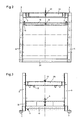
- the device shown in the drawing for detaching ice or press snow layers from traffic areas has a frame 1 which has two side parts 2 which are essentially L-shaped in side view and which are connected to one another in a stiffening manner by transverse bars 24, 25.
- Carrier 4 is provided for fastening the frame 1 to the front of a vehicle 31, which is provided with a lifting cylinder 5 'articulated in the middle of the frame 1 on a support bracket 5'. With the help of this lifting cylinder 5 ', the frame 1 can be raised and lowered.
- skids 7 are fastened with the aid of screws 8.
- Each nozzle tube 10 is equipped with a plurality of high-pressure nozzles 11 pointing downwards.
- twenty high-pressure nozzles 11 are provided on each nozzle tube, the nozzle bores of which have a diameter of 0.1 to 1 mm, preferably 0.3 to 0.5 mm, and which generate a sharp, bundled, cutting liquid jet.
- each nozzle tube 10 has at its two ends adjacent to the horizontal legs 6 of the side parts 2 of the frame 1 in each case an end plate 12 provided with a threaded bore, into which an adjusting screw 13 is screwed.
- the set screw 13 is rotatably received with its lower end portion in a support bearing 14 but axially fixed.
- the support bearings 14 are connected by screws 15 to the horizontal legs 6 of the side parts 2 of the frame 1. By turning the set screws 13, the Nozzle tubes 10 can be adjusted vertically relative to the skids 7.
- the height (FIG. 4) is usually set to values between 50 and 80 mm.
- the nozzle tubes 10 are pivotable in the frame 1 about the horizontal axis of the support bearing 14, so that the liquid jets emerging from the high pressure nozzles 11 strike the top 16 of an ice or press snow layer at an angle which is less than 90 °.
- the end sections of the adjusting screws 13 accommodated in the support bearings 14 can be fixed against rotation by means of clamping screws 17, which are provided with a conical clamping pin 18.
- a distributor pipe 20 is arranged between the vertical legs 3 of the side parts 2 of the frame 1, from which a plurality of lines 21 extend, each of which leads to the individual nozzle pipes 10.
- Each line 21 is provided with an electromagnetically actuated shut-off valve 22, so that one, two, three or all four nozzle tubes 10 can be acted upon with pressurized liquid.
- a liquid 23 having a pressure of up to 70 MPa (preferably up to 20 MPa) is supplied to the distribution pipe 20 by a high pressure pump 33 which is mounted on the vehicle 31 (FIGS. 5 and 6). You can at the same time with a facility for Preheat the liquid supplied to the nozzle pipes 10 via the distributor pipe 20.
- the high-pressure nozzles 11 of the respective neighboring nozzle tubes 10 are arranged in a gap with respect to one another, so that the high-pressure nozzles 11 of the first and third nozzle tubes 10 and high-pressure nozzles of the second and fourth nozzle tubes 10, as seen from the front, are each aligned, ie lie on a common line parallel to the direction of travel. While the distances between the nozzle tubes 10 should not be greater than 30 cm, a maximum of about 15-20 cm is expedient for the distances between the individual rows of nozzles. With smaller distances between the rows of nozzles, however, the work output is greater.
- a 1 to 2 cm thick layer of press snow could easily be detached from a traffic area at a driving speed of 10 km / h.
- Twenty high-pressure nozzles 11 with a nozzle bore of 0.3 mm diameter were attached to a nozzle pipe of 220 cm length, which were charged with water at 8 ° C under a pressure of 20 MPa with a total of 60 g water / m2 traffic area.
- the angle at which the nozzle axes were directed against the top of the press snow layer was 60 °.
- a storage tank 32 for the liquid for the liquid, the high pressure pump 33 and the associated drive motor 34 are arranged.
- a heating device can be assigned to the storage tank 32.
- This heating device can be a heating cartridge inserted via the filling opening of the storage tank 32.
Landscapes
- Engineering & Computer Science (AREA)
- Architecture (AREA)
- Civil Engineering (AREA)
- Structural Engineering (AREA)
- Vehicle Cleaning, Maintenance, Repair, Refitting, And Outriggers (AREA)
- Road Repair (AREA)
Claims (8)
- Procédé pour décoller les couches de glace ou de neige tassée sur les routes, dans lequel un liquide, de l'eau réchauffée ou une solution d'un agent de fusion, notamment, est injecté sous pression, à partir d'un véhicule (31), par des injecteurs (11) guidés sur la route (16), sous les couches de glace ou de neige tassée, à déblayer, caractérisé en ce que le liquide est injecté au travers des couches de glace ou de neige tassée, entre la couche de glace ou de neige et la route (16), par plusieurs injecteurs à haute pression (11), simultanément, disposés en rangées longitudinales et/ou transversales, par rapport au sens de marche (30) du véhicule (31), et mutuellement distantes de quelques centimètres, sous forme de jets sous haute pression, focalisés et nets, dans un sens essentiellement vertical, en découpant simultanément les couches de glace ou de neige tassée, à déblayer.
- Procédé suivant la revendication 1, caractérisé en ce que la couche de glace ou de neige tassée est découpée linéairement, dans le sens de marche, par les jets de liquide, les jets respectifs de plusieurs injecteurs à haute pression (11), disposés dans une rangée, frappant successivement le même point.
- Dispositif pour la réalisation du procédé suivant l'une des revendications 1 et 2, avec un châssis (1) réglable en hauteur, sur lequel est fixée une rampe d'injection (10) au moins, transversale au sens de marche, munie de plusieurs injecteurs à haute pression (11), orientés vers le bas, et raccordée à une conduite (21) d'alimentation en liquide, caractérisé en ce que le châssis (1) est muni de deux rampes d'injection (10) au moins, transversales ou obliques par rapport au sens de marche, et en ce que, dans le sens de marche (30), deux injecteurs à haute pression (11) au moins sont disposés l'un derrière l'autre, en une rangée parallèle au sens de marche.
- Dispositif suivant la revendication 3, caractérisé en ce que les rampes d'injection (10), transversales au sens de marche, présentent une distance mutuelle de 30 cm maximum, et en ce que les injecteurs à haute pression (11) des différentes rampes d'injection (10), respectivement affectés à la même ligne de coupe, présentent un écartement mutuel de 15 cm maximum.
- Dispositif suivant l'une des revendications 3 et 4, caractérisé en ce que le châssis (1) présente deux parties latérales (2) essentiellement en L, assemblées par des traverses (24, 25), un dispositif-support (4), pour la fixation du châssis (1) sur un véhicule (31), étant disposé sur les sections verticales (3) des parties latérales (2).
- Dispositif suivant la revendication 5, caractérisé en ce que des patins (7) sont disposés sur les sections horizontales (6) des parties latérales (2), et en ce qu'une plaque (12) munie d'un taraudage, dans laquelle est vissée une vis de réglage (13), dont la section finale non filetée est logée, avec une possibilité de rotation, dans un palier (14) assemblé avec le châssis (1), est disposée sur les deux extrémités de chaque rampe d'injection (10), pour le réglage en hauteur.
- Dispositif suivant la revendication 6, caractérisé en ce qu'une vis de fixation (17), munie d'un élément de fixation conique (18), de préférence, est disposée dans le palier (14), pour la fixation de la vis de réglage (13).
- Dispositif suivant l'une quelconque des revendications 3 à 7, caractérisé en ce que les injecteurs (11) des rampes d'injection adjacentes (10) sont disposés en chicane les uns par rapport aux autres.
Applications Claiming Priority (2)
| Application Number | Priority Date | Filing Date | Title |
|---|---|---|---|
| AT276087A AT388952B (de) | 1987-10-19 | 1987-10-19 | Verfahren und vorrichtung zum entfernen von eis- oder presschneeschichten von verkehrsflaechen |
| AT2760/87 | 1987-10-19 |
Publications (2)
| Publication Number | Publication Date |
|---|---|
| EP0312945A1 EP0312945A1 (fr) | 1989-04-26 |
| EP0312945B1 true EP0312945B1 (fr) | 1991-10-02 |
Family
ID=3539867
Family Applications (1)
| Application Number | Title | Priority Date | Filing Date |
|---|---|---|---|
| EP19880117196 Expired - Lifetime EP0312945B1 (fr) | 1987-10-19 | 1988-10-15 | Procédé et dispositif pour déblayer les couches de glace ou de neige tassée sur les routes |
Country Status (3)
| Country | Link |
|---|---|
| EP (1) | EP0312945B1 (fr) |
| AT (1) | AT388952B (fr) |
| DE (1) | DE3865288D1 (fr) |
Families Citing this family (5)
| Publication number | Priority date | Publication date | Assignee | Title |
|---|---|---|---|---|
| AT413564B (de) * | 1999-08-23 | 2006-03-15 | Feilhauer Franz | Verfahren zur entfernung von eis- und/oder pressschneeschichten von verkehrsflächen und vorrichtung zur durchführung derselben |
| AT501394B1 (de) * | 2000-02-24 | 2007-06-15 | Feilhauer Franz | Verfahren zur entfernung von eis- und/oder pressschneeschichten von verkehrsflächen |
| DE10304444A1 (de) * | 2003-02-04 | 2004-08-19 | Kastriot Merlaku | Schneeräumungs-Fahrzeug |
| ITVR20090022A1 (it) * | 2009-03-09 | 2010-09-10 | Agristrade S P A | Dispositivo di distribuzione su strada di una soluzione acquosa per l'impiego come antigelo superficiale |
| CN109371894A (zh) * | 2018-12-03 | 2019-02-22 | 东北大学 | 一种具有避障功能的铣削式路面除冰设备 |
Family Cites Families (8)
| Publication number | Priority date | Publication date | Assignee | Title |
|---|---|---|---|---|
| DD70612A (fr) * | ||||
| US1391889A (en) * | 1920-03-08 | 1921-09-27 | Goldman Barney | Snow-mrlting apparatus |
| DE1301356B (de) * | 1966-12-16 | 1969-08-21 | Gross Berliner Strassenreinigu | Verfahren zum Verspruehen von Fluessigkeiten |
| US3456368A (en) * | 1967-05-05 | 1969-07-22 | Lucien Gerard Jacques | Snow removing and melting machine |
| AT321978B (de) * | 1971-04-19 | 1975-04-25 | Zellinger Ing Hans | Regeleinrichtung für ein strassenwaschfahrzeug |
| US4081200A (en) * | 1976-12-10 | 1978-03-28 | Flow Industries, Inc. | Method and apparatus to remove structural concrete |
| JPS5415328A (en) * | 1977-07-04 | 1979-02-05 | Oonori Yoshizawa | Moving snow remover |
| DE3325909A1 (de) * | 1983-07-19 | 1985-01-31 | Gewerkschaft Eisenhütte Westfalia, 4670 Lünen | Schneidduesenvorrichtung fuer vortriebs- und abbaumaschinen u.dgl. |
-
1987
- 1987-10-19 AT AT276087A patent/AT388952B/de not_active IP Right Cessation
-
1988
- 1988-10-15 EP EP19880117196 patent/EP0312945B1/fr not_active Expired - Lifetime
- 1988-10-15 DE DE8888117196T patent/DE3865288D1/de not_active Expired - Fee Related
Also Published As
| Publication number | Publication date |
|---|---|
| ATA276087A (de) | 1989-02-15 |
| DE3865288D1 (de) | 1991-11-07 |
| EP0312945A1 (fr) | 1989-04-26 |
| AT388952B (de) | 1989-09-25 |
Similar Documents
| Publication | Publication Date | Title |
|---|---|---|
| DE69002280T2 (de) | Verfahren zur Reinigung von Start- und Landebahnen. | |
| DE2829148C3 (de) | Verfahren und Vorrichtung zur Beseitigung von Schnee und Eis | |
| EP0560021A1 (fr) | Véhicule pour la réparation de revêtements routiers | |
| EP0757736B1 (fr) | Procede et dispositif de deglacage de voies de circulation impliquant la reutilisation d'une solution de degivrage recuperee | |
| DE2400437C3 (de) | Verfahren und Vorrichtung zum Ablösen einer auf einer Oberfläche festgefrorenen Schicht aus Eis, Schnee oder Reif | |
| EP0312945A1 (fr) | Procédé et dispositif pour déblayer les couches de glace ou de neige tassée sur les routes | |
| DE3426889A1 (de) | Verfahren und vorrichtung zum bearbeiten bzw. zerstoeren von bebauten bzw. befestigten flaechen mittels eines hydraulischen mediums | |
| DE4403243B4 (de) | Spritzvorrichtung zum Aufspritzen von flüssigem bitumenförmigem Bindemittel | |
| EP3333320B1 (fr) | Dispositif et procédé de nettoyage de joints | |
| DE2760337C2 (fr) | ||
| EP0697048A1 (fr) | Procede permettant d'empecher la formation de brouillard sur une section de terrain ou de le dissiper et systeme permettant la mise en uvre dudit procede | |
| AT413564B (de) | Verfahren zur entfernung von eis- und/oder pressschneeschichten von verkehrsflächen und vorrichtung zur durchführung derselben | |
| EP2799156B1 (fr) | Procédé de nettoyage de finisseuses de route ou chargeurs | |
| DE102012002216A1 (de) | Vorrichtung zur Beseitigung von Schnee- oder Eismassen | |
| AT501394B1 (de) | Verfahren zur entfernung von eis- und/oder pressschneeschichten von verkehrsflächen | |
| WO2009149705A2 (fr) | Chasse-neige et procédé de nettoyage et/ou de déblaiement d'aires de trafic dans des aéroports et analogues, en particulier de pistes de décollage et/ou d'atterrissage | |
| AT395877B (de) | Einrichtung zum aufrauhen und einebnen einer mit hartschnee bedeckten und/oder vereisten verkehrsflaeche | |
| DE202015101695U1 (de) | Vorrichtung zum Behandeln von Rissebereichen in Oberflächen von Verkehrsflächen | |
| DE2260383A1 (de) | Vorrichtung zur halterung von aufsatzringen fuer die vertikale verstellung von strassenkappen, messpunkten, hydrantenund schachtabdeckungen od.dgl | |
| DE102015105208A1 (de) | Vorrichtung zum Behandeln von Rissebereichen in Oberflächen von Verkehrsflächen | |
| DD283432A5 (de) | Einrichtung zum verkleben eines, insbesondere aus y-schwellen und schienen gebildeten gleisrostes auf beton-gleisunterbau | |
| CH681095A5 (en) | Ice breaker device for roads and pavements - consists of ribbed jacket, mounted on roller of road vehicle | |
| DE102012001717A1 (de) | Vorrichtung zum Aufschmelzen und Beräumen von Schnee oder Eis | |
| DE2846638C2 (fr) | ||
| DE1658479A1 (de) | Verfahren zum Entziehen von Feuchtigkeit von Oberflaechen verhaeltismaessig grosser Abmessungen und Vorrichtung zur Durchfuehrung des Verfahrens |
Legal Events
| Date | Code | Title | Description |
|---|---|---|---|
| PUAI | Public reference made under article 153(3) epc to a published international application that has entered the european phase |
Free format text: ORIGINAL CODE: 0009012 |
|
| AK | Designated contracting states |
Kind code of ref document: A1 Designated state(s): BE CH DE FR GB IT LI NL SE |
|
| 17P | Request for examination filed |
Effective date: 19890531 |
|
| 17Q | First examination report despatched |
Effective date: 19900606 |
|
| RAP1 | Party data changed (applicant data changed or rights of an application transferred) |
Owner name: HUBERT WEISSER KG |
|
| GRAA | (expected) grant |
Free format text: ORIGINAL CODE: 0009210 |
|
| AK | Designated contracting states |
Kind code of ref document: B1 Designated state(s): BE CH DE FR GB IT LI NL SE |
|
| ITF | It: translation for a ep patent filed | ||
| ET | Fr: translation filed | ||
| GBT | Gb: translation of ep patent filed (gb section 77(6)(a)/1977) | ||
| REF | Corresponds to: |
Ref document number: 3865288 Country of ref document: DE Date of ref document: 19911107 |
|
| PLBE | No opposition filed within time limit |
Free format text: ORIGINAL CODE: 0009261 |
|
| STAA | Information on the status of an ep patent application or granted ep patent |
Free format text: STATUS: NO OPPOSITION FILED WITHIN TIME LIMIT |
|
| 26N | No opposition filed | ||
| PGFP | Annual fee paid to national office [announced via postgrant information from national office to epo] |
Ref country code: GB Payment date: 19931008 Year of fee payment: 6 Ref country code: DE Payment date: 19931008 Year of fee payment: 6 |
|
| PGFP | Annual fee paid to national office [announced via postgrant information from national office to epo] |
Ref country code: SE Payment date: 19931012 Year of fee payment: 6 |
|
| PGFP | Annual fee paid to national office [announced via postgrant information from national office to epo] |
Ref country code: CH Payment date: 19931013 Year of fee payment: 6 |
|
| PGFP | Annual fee paid to national office [announced via postgrant information from national office to epo] |
Ref country code: FR Payment date: 19931015 Year of fee payment: 6 |
|
| PGFP | Annual fee paid to national office [announced via postgrant information from national office to epo] |
Ref country code: BE Payment date: 19931020 Year of fee payment: 6 |
|
| PGFP | Annual fee paid to national office [announced via postgrant information from national office to epo] |
Ref country code: NL Payment date: 19931031 Year of fee payment: 6 |
|
| PG25 | Lapsed in a contracting state [announced via postgrant information from national office to epo] |
Ref country code: GB Effective date: 19941015 |
|
| PG25 | Lapsed in a contracting state [announced via postgrant information from national office to epo] |
Ref country code: SE Effective date: 19941016 |
|
| PG25 | Lapsed in a contracting state [announced via postgrant information from national office to epo] |
Ref country code: LI Effective date: 19941031 Ref country code: CH Effective date: 19941031 Ref country code: BE Effective date: 19941031 |
|
| EAL | Se: european patent in force in sweden |
Ref document number: 88117196.1 |
|
| BERE | Be: lapsed |
Owner name: HUBERT WEISSER K.G. Effective date: 19941031 |
|
| PG25 | Lapsed in a contracting state [announced via postgrant information from national office to epo] |
Ref country code: NL Effective date: 19950501 |
|
| GBPC | Gb: european patent ceased through non-payment of renewal fee |
Effective date: 19941015 |
|
| NLV4 | Nl: lapsed or anulled due to non-payment of the annual fee | ||
| PG25 | Lapsed in a contracting state [announced via postgrant information from national office to epo] |
Ref country code: FR Effective date: 19950630 |
|
| REG | Reference to a national code |
Ref country code: CH Ref legal event code: PL |
|
| PG25 | Lapsed in a contracting state [announced via postgrant information from national office to epo] |
Ref country code: DE Effective date: 19950701 |
|
| EUG | Se: european patent has lapsed |
Ref document number: 88117196.1 |
|
| REG | Reference to a national code |
Ref country code: FR Ref legal event code: ST |
|
| PG25 | Lapsed in a contracting state [announced via postgrant information from national office to epo] |
Ref country code: IT Free format text: LAPSE BECAUSE OF NON-PAYMENT OF DUE FEES;WARNING: LAPSES OF ITALIAN PATENTS WITH EFFECTIVE DATE BEFORE 2007 MAY HAVE OCCURRED AT ANY TIME BEFORE 2007. THE CORRECT EFFECTIVE DATE MAY BE DIFFERENT FROM THE ONE RECORDED. Effective date: 20051015 |