EP0313125A2 - Dispositif de manivelle - Google Patents
Dispositif de manivelle Download PDFInfo
- Publication number
- EP0313125A2 EP0313125A2 EP88202090A EP88202090A EP0313125A2 EP 0313125 A2 EP0313125 A2 EP 0313125A2 EP 88202090 A EP88202090 A EP 88202090A EP 88202090 A EP88202090 A EP 88202090A EP 0313125 A2 EP0313125 A2 EP 0313125A2
- Authority
- EP
- European Patent Office
- Prior art keywords
- drive pinion
- locking
- hub
- crank arm
- coupling
- Prior art date
- Legal status (The legal status is an assumption and is not a legal conclusion. Google has not performed a legal analysis and makes no representation as to the accuracy of the status listed.)
- Granted
Links
Images

Classifications
-
- B—PERFORMING OPERATIONS; TRANSPORTING
- B60—VEHICLES IN GENERAL
- B60J—WINDOWS, WINDSCREENS, NON-FIXED ROOFS, DOORS, OR SIMILAR DEVICES FOR VEHICLES; REMOVABLE EXTERNAL PROTECTIVE COVERINGS SPECIALLY ADAPTED FOR VEHICLES
- B60J7/00—Non-fixed roofs; Roofs with movable panels, e.g. rotary sunroofs
- B60J7/02—Non-fixed roofs; Roofs with movable panels, e.g. rotary sunroofs of sliding type, e.g. comprising guide shoes
- B60J7/04—Non-fixed roofs; Roofs with movable panels, e.g. rotary sunroofs of sliding type, e.g. comprising guide shoes with rigid plate-like element or elements, e.g. open roofs with harmonica-type folding rigid panels
- B60J7/057—Driving or actuating arrangements e.g. manually operated levers or knobs
-
- Y—GENERAL TAGGING OF NEW TECHNOLOGICAL DEVELOPMENTS; GENERAL TAGGING OF CROSS-SECTIONAL TECHNOLOGIES SPANNING OVER SEVERAL SECTIONS OF THE IPC; TECHNICAL SUBJECTS COVERED BY FORMER USPC CROSS-REFERENCE ART COLLECTIONS [XRACs] AND DIGESTS
- Y10—TECHNICAL SUBJECTS COVERED BY FORMER USPC
- Y10S—TECHNICAL SUBJECTS COVERED BY FORMER USPC CROSS-REFERENCE ART COLLECTIONS [XRACs] AND DIGESTS
- Y10S148/00—Metal treatment
- Y10S148/139—Schottky barrier
-
- Y—GENERAL TAGGING OF NEW TECHNOLOGICAL DEVELOPMENTS; GENERAL TAGGING OF CROSS-SECTIONAL TECHNOLOGIES SPANNING OVER SEVERAL SECTIONS OF THE IPC; TECHNICAL SUBJECTS COVERED BY FORMER USPC CROSS-REFERENCE ART COLLECTIONS [XRACs] AND DIGESTS
- Y10—TECHNICAL SUBJECTS COVERED BY FORMER USPC
- Y10T—TECHNICAL SUBJECTS COVERED BY FORMER US CLASSIFICATION
- Y10T74/00—Machine element or mechanism
- Y10T74/20—Control lever and linkage systems
- Y10T74/20396—Hand operated
- Y10T74/20402—Flexible transmitter [e.g., Bowden cable]
- Y10T74/2042—Flexible transmitter [e.g., Bowden cable] and hand operator
-
- Y—GENERAL TAGGING OF NEW TECHNOLOGICAL DEVELOPMENTS; GENERAL TAGGING OF CROSS-SECTIONAL TECHNOLOGIES SPANNING OVER SEVERAL SECTIONS OF THE IPC; TECHNICAL SUBJECTS COVERED BY FORMER USPC CROSS-REFERENCE ART COLLECTIONS [XRACs] AND DIGESTS
- Y10—TECHNICAL SUBJECTS COVERED BY FORMER USPC
- Y10T—TECHNICAL SUBJECTS COVERED BY FORMER US CLASSIFICATION
- Y10T74/00—Machine element or mechanism
- Y10T74/20—Control lever and linkage systems
- Y10T74/20576—Elements
- Y10T74/20732—Handles
- Y10T74/20744—Hand crank
-
- Y—GENERAL TAGGING OF NEW TECHNOLOGICAL DEVELOPMENTS; GENERAL TAGGING OF CROSS-SECTIONAL TECHNOLOGIES SPANNING OVER SEVERAL SECTIONS OF THE IPC; TECHNICAL SUBJECTS COVERED BY FORMER USPC CROSS-REFERENCE ART COLLECTIONS [XRACs] AND DIGESTS
- Y10—TECHNICAL SUBJECTS COVERED BY FORMER USPC
- Y10T—TECHNICAL SUBJECTS COVERED BY FORMER US CLASSIFICATION
- Y10T74/00—Machine element or mechanism
- Y10T74/20—Control lever and linkage systems
- Y10T74/20576—Elements
- Y10T74/20732—Handles
- Y10T74/20744—Hand crank
- Y10T74/20756—Collapsible
Definitions
- the invention relates to a crank device for driving a movable member of a vehicle, such as a panel of an open roof construction. More particularly, the invention relates to a crank device comprising a stationary part, a drive pinion operatively connected to the movable member and rotatably supported by the stationary part, and a crank arm connected to the drive pinion during said driving operation.
- crank devices are known in various embodiments with open roof constructions for automobiles. Since the crank devices have to be operated fully manually by means of the crank arm, these crank devices require more attention of the driver of the vehicle compared to electrically operated open roof constructions. Furthermore, the crank arm gives additional problems, because it protrudes from the roof lining at least in the operative position and could therefore cause a risk of injuries if no special measurements would have been taken.
- the present invention has as its first object to provide a crank device of the type mentioned in the preamble, which, for the operation thereof, requires only little attention of the driver of the vehicle and offers the comfort and safety of an electrically driven open roof construction.
- a further object of the present invention is to provide a crank device comprising a very accurately operating locking means, the locking of which can be released in a simple way.
- Still another object of the invention is to provide a crank device provided with an uncoupling means for uncoupling the crankarm with respect to the drive pinion, which is operable in a simple way and effects an automatic recoupling.
- crank device provided with an indication means, the position of which is determining for the position of the movable member.
- a first embodiment of the crank device according to the invention is characterized by a locking means co-operating with the drive pinion and the stationary part to lock the crank device in a predetermined position of the movable member, and provided with means for releasing the locking of the crank device by the locking means; a breaking means effective between the drive pinion and the stationary part to permit a rotation of the drive pinion through the crank arm and to prevent a rotation of the drive pinion by the movable part.
- the locking means permits the movable member to be placed automatically in a desired predetermined position without the necessity of the driver to divert the driver,s attention from the traffic.
- the breaking means prevents a displacement of the movable member by means of forces exerted on the movable member caused for instance by the driving wind or with breaking-in.
- the uncoupling means allows the crank arm to be uncoupled from the drive pinion in all positions of the movable member and to be moved to a stowed resting position without displacing the movable member.
- this free travel back-lash can be utilized to release the locking of the drive pinion with respect to the stationary part. In this way, it is sufficiently for realising the locking of the drive pinion to rotate the crank arm back.
- a further embodiment of the crank device according to the invention is characterized by stop means having a stop member and rotating with the drive pinions in a fixed relationship, the stop means comprising two co-operating rotable elements, of which a stop element is provided with the stop member and a retaining element being provided with a releasing member; a locking member automatically coming into engagement with the stop member of the stop element in a predetermined position of the movable member in order to lock the driving of the movable member in the predetermined position; means for releasing the locking, wherein the stop element and the retaining element have mutually different transmissionratios to the drive pinion, chosen such that the releasing member on the retaining element permits an engagement between the locking member and the stop member only in a mutual rotational position of both elements corresponding to the predetermined position of the movable member.
- the stop member is connected directly to the drive pinion, so that the stop member rotates with the same rotational speed as the drive pinion.
- the stop member is integrally formed with the drive pinion and is constructed as a stop disc disposed concentrically about the axis of the drive pinion, a recess being formed in the periphery of the stop disc, the recess serving as a stop element and the locking member being able to engage into said recess.
- the retaining element consists of a retaining ring arranged concentrically about the axis of the drive pinion and being in engagement with the drive pinion through a reduction transmission, a resilient element acting upon the locking member in radial direction of the drive pinion and keeping the locking member in contact with the periphery of the retaining ring, the releasing member consisting of a recess provided in the periphery of the retaining ring and being alinged with the recess in the stop disc in the predetermined position of the movable member such that the locking member can engage in the recess in the stop disc.
- a further embodiment of the crank device according to the invention is characterized by an uncoupling means provided between the drive pinion and the crank arm to uncouple the crank arm with respect to the drive pinion such that the crank arm can be rotated about the axis of the drive pinion without rotating the drive pinion, wherin the uncoupling means is provided with a coupling member adapted to be manually displaced from a coupling position to an uncoupling position, and the coupling member being permitted to return automatically to the coupling position after rotating the crank arm to a predetermined position and bringing the crank arm back to the position in which it was uncoupled.
- Said uncoupling means for the crank device has the advantage that first of all a very simple uncoupling of the crank arm with respect to the drive pinion takes place, while furthermore the crank arm has always a reproducable relation with respect to the drive pinion in its coupled position.
- the drive pinion is provided with a hub consisting of two co- axial rotatable hub parts, the first hub part being connected to the drive pinion and the crank arm being mounted to the second hub part, the coupling member being arranged to the first and second hub parts and coupling both hub parts in a non-rotatable relationship in its coupling position and uncouple both hub parts with respect to each other in its uncoupling position.
- the coupling member comprises at least one coupling pin being slidable in axial holes formed in both hub parts and being loaded in a direction to its coupling position by a spring element.
- the coupling member consists of a coupling cam mounted to an actuating rotary knob being rotatable about said shaft between the coupling position and the uncoupling position, wherein the coupling cam engages in the recess in the first hub part in the coupling position of the actuating rotary knob and is brought out of engagement with the first hub part in the uncoupling position of the actuating rotary knob.
- a further embodiment of the crank device according to the invention is characterized by a rotating ring disposed concentrically about a shaft of the drive pinion and serving as an indicating means for the position of the movable member; a reduction transmission provided between the drive pinion and the rotating ring and constructed as a toothed wheel disposed between the drive pinion and the rotating ring, wherein the rotating ring comprises a full tooting being constantly in engagement with the thooted wheel, the drive pinion being provided with a small number of teeth coming intermittently in engagement with the toothed wheel such that a continuous rotation of the drive pinion is converted by the reduction transmission into a reduced discontinuous rotation of the rotating ring.
- Said rotating ring can, at first, be used as retaining ring of the locking means, and it forms also an indicating means for the position of the movable member, in case the reduction transmission is such that the rotating ring rotates less than one full rotation when the movable member is displaced between its extreem positions.
- Fig. 1 shows a crank device for driving a panel (not shown) of an open roof construction, in particularly a panel of a tilt-sliding roof for an automobile.
- the panel of the tilt-slidingroof is adapted to be displaced by means of the crank device between a closed position and a backwardly slit position below the fixed roof of the automobile on one side and between the closed position and an backwardly and upwardly inclined venting position on the other side.
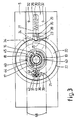
- the crank device has a drive pinion rotatably supported on a stationary hollow vertical shaft 1 and provided on its upper side with a toothing 3 in engagement with pull-push cables 68 (illustrated by a dash and dot line) comprising circumferential ribs and converting the rotation of the drive pinion 2 into a sliding movement of an actuating element for the panel.
- the stationary vertical shaft l is fixed to a horizontal plate means 4 also carrying a housing means 5.
- the plate means 4 and the housing means 5 together may be mounted to the frame of the tilt-sliding roof by means of screws or the like.
- the drive pinion 2 is connected to a hub 6 on its end facing away from the toothing 3, the hub 6 including two co-axial hub parts 7 and 8, of which the first hub part 7 being rotatably mounted on the vertical shaft l and being in engagement with the drive pinion 2, and the second hub part 8 being rotatably mounted on the first hub part 7.
- a mounting plate 70 connected to the stationary shaft 1 by means of a threaded connection 69 confines the hub part 7 and 8 radially.
- a crank arm 9 is pivotally connected to the second hub part 8 at its one end by means of a horizontal shaft 10. At the end of the crank arm facing away from the hub 6 the crank arm 9 is provided with a knob 11 to grip the crank arm 9 by hand.
- the crank arm 9 has to stable positions: an operative position illustrated by uninterupted lines, in which the crank device can be operated by means of the crank arm, and a resting position illustrated by dashed lines, in which the crank arm 9 is stowed away in a recess (not shown) in a roof lining 12 illustrated by dash and dot lines.
- crank arm 9 is arrested in said stable positions by a spring 14 clamped in between the hub part 8 and a cam 13 on the crank arm 9, the torque of the spring 14 about the shaft 10 changing between the operative position and the resting position of the cramnk arm 9.
- the crank arm 9 In an unstable central position indicated by dash and dot lines the crank arm 9 extends parallel to the roof lining 12.
- the crank device comprises a breaking means preventing a rotation of the drive pinion 2 through the panel.
- a torsion spring 15 is mounted around the stationary vertical shaft 1 and frictionally engages this shaft, said torsion spring comprising a plurality of windings and two projecting ends 16 and 17.
- the frictional force between the torsion spring 15 and the stationary shaft 1 is so strong that no rotation of the torsion spring 15 with respect to the stationary shaft 1 can take place.
- the drive pinion 2 and the hub part 7 of the hub 6 are provided with co-operating arc- shaped wall portions 18 and 19 respectively, which can engage the projecting spring ends 16, 17 or each other.
- the wall portions 18 and 19 extend such a circular arc that a free movement of approximately 60° between a drive pinion 2 and the hub part 7 is permitted.
- the wall portion 19 thereof engages a spring ends 16 or 17 respectively, whereupon the torsion spring 15 is deformed to such extent that the friction between said spring and the stationary shaft 1 becomes smaller.
- a rotation of the torsion spring 15 about the shaft 1 is possible, whereupon at the end of the free movement between the wall portions 18 and 19 the wall portion 19 at the hub part 7 can come into engagement with the wall portion 18 of the drive pinion 2, so that upon a further rotation of the hub part 7 a rotation of the drive pinion 2 is effected.
- the crank device further comprises a locking means locking the drive pinion 2 in predetermined positions of the panel, in this case the closed position of the panel between the backwardly slit position and the upwardly tilted position of the panel.
- the purpose of the locking means is to lock the drive pinion automatically in the closed position of the panel when the panel is moved from one of the opened positions to the closed position, so that the panel is always closed automatically in the right position.
- the locking means comprises a stop disc 20 formed integrally with the drive pinion 2 and disposed co-axialy therewith, as well as a co-axial retaining ring 22 rotatably connected with the drive pinion by means of a reduction transmission 21 to be described hereinafter.
- the transmission ratio of the reduction transmission 21 between the retaining ring 22 and the drive pinion 2 is chosen such that an adjustment of the panel from the extreme upwardly tilted position to the extreme backwardly slit position corresponds to a rotation of the retaining ring 22 along an angle of slightly less than 360°.
- the rotational position of the retaining ring 22 gives an indication about the position of the panel, since every position of the retaining ring 22 corresponds to a small range of positions of the panel, and in combination with the stop disc 20 an exact relationship between the position of the panel and that of the retaining ring 22/stop disc 20 is present.
- a right angled recess 23 is formed serving as stop member, and in the periphery of the retaining ring 22 a recess 24 working as releasing member is provided, said recess 22 extending in radial direction slightly further inwardly direction than the panel, and in combination with the stop disc 20 an exact relationship between the position of the panel and that of the retaining ring 22/stop disc 20 is present.
- a right angled recess 23 is formed serving as stop member
- a recess 24 working as releasing member is provided in the periphery of the retaining ring 22 .
- a rectangular cavity 26 is formed extending radially with respect to the drive pinion 2 and receiving a rectangular locking pin 27.
- a smaller locking cam 29 is provided at the end of the locking pin 27 facing the drive pinion 2 having a width permitting the nose 28 to enter the recess in the stop disc 20 and to lock the drive pinion 2 in this manner.
- the locking pin 27 has a depression 29 opening at the end of the locking pin 27 facing away from the drive pinion 2 and receiving a helical spring 30 partially, the helical spring 30 resting against the back wall of the cavity 26 and thereby loading the locking pin 27 in the direction to the retaining ring 22 and the stop disc 20 of the drive pinion 2.
- the locking pin 27 is received in the cavity 26 with play in the axial direction to the drive pinion 2, such that the locking pin 27 can be urged against the force of a leaf spring 31 in a direction facing away from the hub 6.
- a covering plate 33 mounted to the housing means 5 by screws 32 closes the cavity 26 at the lower side.
- the hub part 7 of the hub 6 is provided with a rib 34 on its side facing the drive pinion 2, the rib 34 being able to co-operate with a cam 35 formed on the locking pin 27 on the side thereof facing the hub part 7.
- the retaining ring 22 of the locking means In any open position of the panel of the tilt-sliding roof the retaining ring 22 of the locking means is rotated such, that the recess 24 thereof is spaced from the locking pin 27.
- the locking pin 27 is resting with its locking nose 28 against the outher periphery of the retaining ring 22.
- the locking nose 29 is dimensioned in axial direction of the drive pinion 2 such that is also extends along the height of the stop disc 20 in its initial position.
- the stop disc 20 rotates with the same rotational speed as the drive pinion 2, so that with each rotation of the drive pinion 2 the recess 23 passes the locking pin 27.
- the locking nose 29 of the locking pin 27 rests against the periphery of the retaining ring 22, of which the diameter is slightly larger than that of the stop disc 20, the locking pin 27 remains in its initial position each time it passes the recess 23 in the stop disc 20.
- the driver wishes to open the panel of the tilt-sliding roof again back to the same opened position or further to another opened position, he should first turn the hub 6 back along its free stroke with respect to the drive pinion 2 by means of the crank arm 9.
- the rib 34 on the hub part 7 will contact the cam 35 of the locking pin 27 lying in the path of the rib 34 in the locking position of the locking pin 27 (the cam 35 ies outwardly of the path of the rib 34 in the initial position of the locking pin 27).
- the locking nose 29 is not anymore in engagement with the recess 23 in the stop disc 20 the locking action of the stop disc 20 and thereby of the drive pinion 2 is released.
- the drive pinion 2 is allowed to be rotated by the hub 6 in both directions.
- the retaining ring 22 is also rotated to a reduced extent through the reduction transmission 21.
- one of the inclined side walls 25 of the recess 24 in the retaining ring 22 is brought into engagement with the locking nose 29 of the locking pin 27, so that the locking pin 27 is urged radially outwardly by the inclined side wall 25.
- the locking nose 28 will be displaced outwardly to such an extent that the locking nose 28 will be brought out of engagement with the side of the stop disc 20 facing away from the hub 6. Consequently, the locking pin 27 is urged back in axial direction to its initial position by the bent leaf spring 31, wherein the locking nose 29 rests against the periphery of the retaining ring 22 and also extends along the height of the stop disc 20, so that the locking pin 27 is allowed to lock the stop disc 20 when the panel reaches the closed position.
- the reduction transmission 21 comprises a toothed wheel 26 arranged radially between the drive pinion 2 and the surrounding retaining ring 22.
- This toothed wheel 36 has a pivot pin 37 extending parallel to the axis of the drive pinion 2 and being journalled in a hole 38 in the housing means 5.
- the retaining ring 22 being provided with a complete toothing 39 at its inner periphery the thooting 39 extending along the full height of the toothed wheel 36 and being constantly in engagement with the toothed wheel 36.
- the drive pinion 2 is provided at its outher periphery with only two teeth 40 with an angular spacing of 180°. When the drive pinion 2 is rotated these teeth 40 come intermittently in engagement with the toothed wheel 36 such that a continoues rotation of the drive pinion 2 is converted by the reduction transmission 21 into a discontinues rotation of the retaining ring 22.
- the toothed wheel 36 consists of two axially seperated non-rotatingly connected toothed wheel parts 41 and 42 each having the same number of teeth 43 in this case 3.
- the teeth 43 of both toothed wheel parts 41, 42 are off-set a half circular pitch with respect to each other and the teeth 43 are arranged in such a way, that the teeth 43 of both toothed wheel parts 41 and 42 together form a complete toothing, such that successively a tooth 43 of the one toothed wheel part 41 and a tooth 43 of the other toothed wheel part 42 comes into engagement with the toothing 39 of the retaining ring 22.
- a collar 44, 45 respectively extends in the circumferencial direction of the drive pinion 2, the collar having a radius substantially equal to the distance between the axis of the drive pinion 2 and the top of the teeth 40 thereof.
- Said collar 44 at one half of the drive pinion 2 extends only along the height of the one toothed wheel part 41, the collar 45 at the other half of the drive pinion 2 only extending along the height of the other toothed wheel part 42.
- the collar 44, 45 thus prevents a rotation of the toothed wheel 36 and consequently of the retaining ring 22 except for a rotation thereof by the drive pinion 2.
- the operation of the reduction transmission 21 is as follows.
- a tooth 43 of the toothed wheel part 41 is in engagement with the toothing 39 of the retaining ring 22.
- the opposite tooth 43 of the other toothed wheel part 42 extends up to the path of the teeth 40 of the drive pinion 2.
- This tooth 43 of the toothed wheel part 42 of the toothed wheel 36 also extends beyond the outer periphery of the collar 44 of the drive pinion 2, the collar 44 extending at the height of the other toothed wheel part 41. If the toothed wheel 36 would be rotated by the toothing 39 of the retaining ring 22, one of the teeth 43 of the toothed wheel part 41 will contact the collar 44 thereby preventing a further rotation of the toothed wheel 36.
- the crank device is further provided with an uncoupling means for uncoupling the crank arm 9 with respect to the drive pinion 2, so that the crank arm 9 is allowed to rotate about the axis of the drive pinion 2 without rotating this drive pinion 2.
- the purpose thereof is to be able to uncouple the crank arm 9 in every position of the drive pinion 2 and consequently every position of the panel of the tilt-sliding roof and to rotate the crank arm 9 to its resting position in a recess in the roof lining without changing the position of the panel.
- both hub parts have a plurality of axial holes 46, 47 respectively spaced about their axes, the holes 46 and 47 being aligned with each other in the coupling position of both hub parts 7 and 8.
- a coupling pin 49 serving as coupling member is slidably arranged in each hole 46 .
- These coupling pins 49 have a length which is larger than the thickness of the hub part 7 at the position of this hole 46.
- Each coupling pin 49 is loaded by a helical spring 49 at its end facing away from the hub part 8, the helical spring 49 acting upon the coupling pins 49 through a flat ring 50 and loading the coupling pins 49 in the direction to the hub part 8 if the coupling pins 48 protrude from the hub part 7 on the side thereof facing away from the hub part 8.
- the coupling pins 49 extent both through the holes 46 in the hub part 7 and into the holes 47 in the hub part 8, so that both hub parts 7 and 8 are non-rotatably connected with each other.
- the uncoupling means is further provided with an actuating means for the coupling pins 49 consisting of an actuating knob 51 being axially slidably mounted to the hub part 8 and comprising a plurality of actuating pins 52 slidably received in the holes 47 for the coupling pins 48.
- a helical spring 53 arranged between the hub part 8 and the actuating knob 51 loads the actuating knob 51 in the direction to its coupling position in which the actuating pins 52 only partially protrude into their respective holes 47 in the hub part 8.
- the actuating pins 52 extend precisely along the whole length of their respective holes 47 in the hub part 8 in the uncoupling position of the actuating knob 51.
- the actuating knob 51 further comprises a latching member latching the actuating knob 51 in its uncoupling position.
- This latching member consists of an axially extending peg 55 protruding into a cavity of the vertical stationary shaft 1 and being fixed to the actuating knob 51 at its lower end. At the other end the peg 55 is provided with two outwardly springing legs 56 and the free end of each leg being formed a latching nose 57. In the uncoupling position of the actuating knob 51, the latching noses 57 protrude from the cavity 54 in the stationary shaft 1 and engaging the end face 59 at the respective end of the stationary shaft 1, so that the actuating knob 51 is latched in this uncoupling position.
- axial faces 59 are provided on fixed pieces 60, the faces 59, which serve as releasing means, being formed on both sides of the cavity 54 in the stationary shaft 1 and extend up to the circumference thereof.
- the faces 59 of the fixed pieces 60 are positioned such that in the position of the hub part 8, in which the crank arm is below the recess in the roof lining 12, the latching noses 57 are urged inwardly by the engagement with the faces 59 of the fixed pieces 60 to such an extent that the engagement between the latching noses 57 and the end face 59 of the stationary shaft 1 is released and the peg 55 of the actuating knob 51 is allowed to be displaced to the coupling position by the helical spring 53.
- crank arm 9 By means of the crank arm 9, which is in its operative position, the drive pinion 2 is rotated and the panel of the tilt-sliding roof is moved to a desired position.
- desired position it is desirable that the crank arm 9 is stowed away in the recess in the roof lining 12, since in this stowed away resting position of the crank arm 9 there is a smaller risk of injuries of the passengers by the crank arm 9 in case of an accident.
- crank arm 9 will not be positioned precisely under the recess in the roof lining 12 when the panel is in its desired position, so that the crank arm has to be rotated about the axis of the drive pinion 2 to the right position under the recess in the roof lining 12, during which the position of the panel of the tilt-sliding roof should not be changed.
- the actuating knob 51 is depressed to its uncoupling position. The engagement between the latching noses 57 and the end face 59 of the stationary shaft 1 causes the actuating knob 51 to be latched in this uncoupling position.
- the coupling pins 48 When the actuating knob 51 and thereby the actuating pins 52 are moved to their uncoupling position, the coupling pins 48 will be maintained in their uncoupling position, since the holes 47 in the hub part 8 and the holes 46 in the hub part 7 are not aligned with each other so that the coupling pins 48 rest on the face of the hub part 8 facing the hub part 7. If the driver wishes to move the panel of the tilt- sliding roof again, the crank arm 9 first has to be moved from its resting position in the recess in the roof lining 12 to the operative position, and thereupon the crank arm 9 and the hub part 8 should be rotated about the axis of the drive pinion 2.
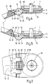
- Fig. 4-6 show an alternative embodiment of the uncoupling means of the crank device.
- the uncoupling of the crank arm 9 with respect to the drive pinion 2 takes place again by uncoupling the hub part 8 with respect to the hub part 7.
- the coupling member consists of a coupling cam 61 formed on an actuating rotary knob 62 which is rotatable about the shaft 10 between the crank arm 9 and the hub part 8.
- the coupling cam 61 thereof engages in a recess 63 in the hub part 7, and in the uncoupling position of the actuating rotary knob 62, the coupling cam 61 is moved out of engagement with the first hub part 7.
- the actuating rotary knob 62 is adapted to be rotated manually from the coupling position to the uncoupling position.
- the actuating rotary knob has a knurled surface 64.
- a knurled surface 64 Als an alternative for the curved knurled surface 64 it is also possible to provide an actuating rib 65 illustrated by a dash and dot line.
- a substantially omega-shaped spring 66 is arranged, of which the central part is placed in a notch 67 of the actuating rotaty knob 62, and both legs of the spring 66 being supported in the cam of the crank arm 9.
- the spring 66 arrests the actuating rotary knob 62 both in the coupling position (spring 66 illustrated by uninterupted lines), and in the uncoupling position (spring 66 indicated by dash and dot lines) so that, when the actuating rotary knob 62 is manually rotated, it automatically looks for the coupling or uncoupling position respectively after an unstable central position.
- the spring 66 In the collapsed resting position of the crank arm, in which the actuating rotary knob 62 is in the uncoupling position, the spring 66 is pivoted with respect to the actuating rotary knob 62 such that this spring 66 loads the actuating rotary knob 62 in a direction to its coupling position.
- the actuating rotary knob 62 can be rotated by a finger from the coupling position to an uncoupling position when the panel of the tilt-sliding roof has reached its desired position.
- the spring 66 exerts upon the actuating rotary knob 62 such a torque about the shaft 10 that the actuating rotary knob 62 is arrested in the uncoupling position. Because the coupling cam 61 is removed from the recess 63 in the hub part 7, the hub part 8 is permitted to be rotated about the axis of the vertical shaft 1 by means of the crank arm 9 without the hub part 7 being rotated.
- crank arm 9 If the right position of the crank arm 9 under the recess in the roof lining is reached, the crank arm 9 is allowed to be pivoted from its operative position to the resting position in the recess of the roof lining. In this position the crank arm 9 is arrested by the spring 14. When the crank arm 9 is pivoted from the operative position to the resting position the spring 66 is pivoted with respect to the actuating rotary knob 62 such that the torque thereof on the actuating rotary knob is reversed and the actuating rotary knob 62 is consequently loaded by the spring 66 in a direction to its coupling position.
- the invention is not restricted to the embodiments shown in the drawing by way of example, which can be varied in different ways within the scope of the invention. As an example it is possible to use the invention in other open roof constructions, such as spioler roofs.
Landscapes
- Engineering & Computer Science (AREA)
- Mechanical Engineering (AREA)
- Transmission Devices (AREA)
- Mechanical Operated Clutches (AREA)
- Liquid Crystal (AREA)
Applications Claiming Priority (2)
| Application Number | Priority Date | Filing Date | Title |
|---|---|---|---|
| NL8702494 | 1987-10-19 | ||
| NL8702494A NL8702494A (nl) | 1987-10-19 | 1987-10-19 | Slingerinrichting. |
Publications (3)
| Publication Number | Publication Date |
|---|---|
| EP0313125A2 true EP0313125A2 (fr) | 1989-04-26 |
| EP0313125A3 EP0313125A3 (en) | 1990-12-19 |
| EP0313125B1 EP0313125B1 (fr) | 1993-12-22 |
Family
ID=19850792
Family Applications (1)
| Application Number | Title | Priority Date | Filing Date |
|---|---|---|---|
| EP88202090A Expired - Lifetime EP0313125B1 (fr) | 1987-10-19 | 1988-09-26 | Dispositif de manivelle |
Country Status (4)
| Country | Link |
|---|---|
| US (2) | US4928547A (fr) |
| EP (1) | EP0313125B1 (fr) |
| DE (1) | DE3886498T2 (fr) |
| NL (1) | NL8702494A (fr) |
Cited By (1)
| Publication number | Priority date | Publication date | Assignee | Title |
|---|---|---|---|---|
| NL1006841C2 (nl) * | 1997-08-25 | 1999-02-26 | Inalfa Ind Bv | Slingerinrichting voor het aandrijven van een beweegbaar deel van een voertuig. |
Families Citing this family (21)
| Publication number | Priority date | Publication date | Assignee | Title |
|---|---|---|---|---|
| DE8909180U1 (de) * | 1989-07-28 | 1989-09-14 | Mösslacher, Hannes, 8000 München | Handkurbelbetreibbarer Notantrieb |
| US5074162A (en) * | 1990-03-14 | 1991-12-24 | Teleflex Incorporated | Local station clutch |
| DE4026754C1 (fr) * | 1990-08-24 | 1991-08-01 | Rockwell Golde Gmbh, 6000 Frankfurt, De | |
| US5168770A (en) * | 1991-08-15 | 1992-12-08 | Ellis Frederick G | Pivotal handle for a window actuator |
| KR950008931B1 (ko) * | 1992-07-22 | 1995-08-09 | 삼성전자주식회사 | 표시패널의 제조방법 |
| US5399896A (en) * | 1992-09-29 | 1995-03-21 | Mitsubishi Denki Kabushiki Kaisha | FET with a T-shaped gate of a particular structure |
| US5400473A (en) * | 1993-08-27 | 1995-03-28 | Great Lakes Window Inc. | Foldaway window crank handle with a handle retention spring |
| US5551316A (en) * | 1995-01-23 | 1996-09-03 | Blank; Jay L. | Retractable window crank |
| US5740632A (en) * | 1995-05-18 | 1998-04-21 | Andersen Corporation | Multi-position window operator handle |
| WO1997035298A2 (fr) * | 1996-03-18 | 1997-09-25 | Philips Electronics N.V. | Dispositif d'affichage |
| DE19930057A1 (de) * | 1999-06-30 | 2001-01-04 | Volkswagen Ag | Versenkbare Drehkurbel für ein Fahrzeug |
| US6753580B1 (en) * | 2000-05-05 | 2004-06-22 | International Rectifier Corporation | Diode with weak anode |
| GB2369392B (en) * | 2000-11-24 | 2003-12-17 | Louver Lite Ltd | A method and apparatus for operating a blind |
| US6592163B1 (en) | 2002-05-03 | 2003-07-15 | Michael W. Nebel | Releasable drive for a slide-out room of a recreational vehicle |
| US20040113116A1 (en) * | 2002-11-20 | 2004-06-17 | London Larry R. | Remote valve actuator |
| US6892495B2 (en) * | 2003-06-16 | 2005-05-17 | Arvinmeritor Lvs Espana, S.A. | Braking system for a vehicle manual window-lifting mechanism |
| NZ533760A (en) * | 2004-07-28 | 2007-02-23 | Assa Abloy New Zealand Ltd | A window operator handle |
| US20060260431A1 (en) * | 2005-05-17 | 2006-11-23 | Armada Toolworks Ltd. | Window handle |
| US9404302B2 (en) | 2012-07-03 | 2016-08-02 | Reflection Window Company, Llc | Systems and methods for unlocking/locking and opening/closing windows |
| US9273763B2 (en) | 2012-07-03 | 2016-03-01 | Elston Window & Wall, Llc | Systems and methods for unlocking/locking and opening/closing windows |
| US12421780B2 (en) * | 2023-10-05 | 2025-09-23 | Hoppe Holding Ag | Crank for window operator |
Family Cites Families (17)
| Publication number | Priority date | Publication date | Assignee | Title |
|---|---|---|---|---|
| DE256049C (fr) * | ||||
| US3148913A (en) * | 1961-12-30 | 1964-09-15 | Golde Hans | Manually operable device for operating a sliding roof |
| NL172277C (nl) * | 1973-07-02 | 1983-08-01 | Rockwell Golde Gmbh | Inrichting voor het begrenzen van het aantal omwentelingen van een as of dergelijke, in het bijzonder voor een draaiaandrijving van een schuifdak van een motorvoertuig. |
| DE2426765A1 (de) * | 1974-06-01 | 1975-12-11 | Webasto Werk Baier Kg W | Kurbelantrieb fuer hebe-schiebedaecher von kraftfahrzeugen |
| NL8103376A (nl) * | 1981-07-16 | 1983-02-16 | Philips Nv | Weergeefinrichting. |
| DE3213708A1 (de) * | 1982-04-14 | 1983-10-20 | Webasto-Werk W. Baier GmbH & Co, 8035 Gauting | Kurbelantrieb |
| JPS58221562A (ja) * | 1982-06-18 | 1983-12-23 | Fuji Xerox Co Ltd | 原稿読取装置 |
| DE3433600C2 (de) * | 1983-12-17 | 1987-03-19 | Webasto-Werk W. Baier GmbH & Co, 8035 Gauting | Vorrichtung zum Steuern der Verschiebe- und Ausstellbewegung des Deckels von Schiebehebedächern |
| SE448701B (sv) * | 1983-12-17 | 1987-03-16 | Webasto Werk Baier Kg W | Anordning for styrning av skjutrorelsen och uppfellningsrorelsen hos luckan vid med taklucka forsedda fordon |
| NL8400094A (nl) * | 1984-01-11 | 1985-08-01 | Vermeulen Hollandia Octrooien | Opendakconstructie voor een voertuig. |
| NL8400228A (nl) * | 1984-01-25 | 1985-08-16 | Vermeulen Hollandia Octrooien | Opendakconstructie voor een voertuig. |
| JPS60177683A (ja) * | 1984-02-23 | 1985-09-11 | Nec Corp | 薄膜形光電変換素子とその製造方法 |
| US4712872A (en) * | 1984-03-26 | 1987-12-15 | Canon Kabushiki Kaisha | Liquid crystal device |
| DE3545869A1 (de) * | 1985-03-27 | 1986-10-09 | Webasto-Werk W. Baier GmbH & Co, 8035 Gauting | Fahrzeugdach |
| JPH0438064Y2 (fr) * | 1986-03-18 | 1992-09-07 | ||
| JPS63204667A (ja) * | 1987-02-19 | 1988-08-24 | Fujitsu Ltd | 半導体装置の製造方法 |
| DE8806189U1 (de) * | 1988-05-10 | 1988-07-28 | Karosseriewerke Weinsberg Gmbh, 7102 Weinsberg | Antriebsvorrichtung für ein Kraftfahrzeug-Schiebehebedach |
-
1987
- 1987-10-19 NL NL8702494A patent/NL8702494A/nl not_active Application Discontinuation
-
1988
- 1988-09-26 DE DE3886498T patent/DE3886498T2/de not_active Expired - Fee Related
- 1988-09-26 EP EP88202090A patent/EP0313125B1/fr not_active Expired - Lifetime
- 1988-10-17 US US07/258,390 patent/US4928547A/en not_active Expired - Lifetime
-
1990
- 1990-05-09 US US07/521,052 patent/US4997788A/en not_active Expired - Fee Related
Cited By (2)
| Publication number | Priority date | Publication date | Assignee | Title |
|---|---|---|---|---|
| NL1006841C2 (nl) * | 1997-08-25 | 1999-02-26 | Inalfa Ind Bv | Slingerinrichting voor het aandrijven van een beweegbaar deel van een voertuig. |
| EP0899141A1 (fr) * | 1997-08-25 | 1999-03-03 | Inalfa Industries B.V. | Mécanisme à manivelle pour l'entrainement d'une partie mobile de véhicule |
Also Published As
| Publication number | Publication date |
|---|---|
| EP0313125B1 (fr) | 1993-12-22 |
| DE3886498D1 (de) | 1994-02-03 |
| DE3886498T2 (de) | 1994-07-28 |
| US4928547A (en) | 1990-05-29 |
| NL8702494A (nl) | 1989-05-16 |
| US4997788A (en) | 1991-03-05 |
| EP0313125A3 (en) | 1990-12-19 |
Similar Documents
| Publication | Publication Date | Title |
|---|---|---|
| EP0313125B1 (fr) | Dispositif de manivelle | |
| US5617760A (en) | Shift lever for a motor vehicle transmission | |
| US5893439A (en) | Parking mechanism for a vehicle equipped with an automatic transmission | |
| US5692589A (en) | Mechanism for controlling a rotary member by means of a pivoting handle, and seat equipped with such a mechanism | |
| US4337978A (en) | Mechanism for adjusting inclination angle of seat | |
| US5794748A (en) | Park lock mechanism for an automatic transmission | |
| US4413712A (en) | Device for locking an element in a stationary position for an automobile vehicle | |
| US20180216373A1 (en) | Motor vehicle handle | |
| US4458920A (en) | Tensionless seat belt retractor | |
| US4986143A (en) | Transmission shift control mechanism with park lock | |
| US4977789A (en) | Vehicle shift lever assembly | |
| US4082008A (en) | Positioning mechanism for automotive seat, window or similar part | |
| US3201536A (en) | Turn signal apparatus with automatic premature prevention cancelling means | |
| GB2036212A (en) | Transmission lock mechanisms | |
| JPH0452358B2 (fr) | ||
| JPS6056654B2 (ja) | 安全ベルト自動巻取装置 | |
| US3368421A (en) | Break-away shift lever | |
| EP0976606B1 (fr) | Système d'inclinaison de siège | |
| EP0154046B1 (fr) | Construction d'un toit ouvrant pour véhicules | |
| JP3289034B2 (ja) | 車両用可動ステップの駆動装置 | |
| KR960001132B1 (ko) | 자동차의 슬라이딩 루우프용 로타리 드라이브 축의 회전수 제한 기구 | |
| JPH0630528Y2 (ja) | セレクタレバー装置 | |
| NL1006841C2 (nl) | Slingerinrichting voor het aandrijven van een beweegbaar deel van een voertuig. | |
| JPH06293221A (ja) | 自動車のスライディングルーフの回転駆動シャフトの回転数を制限する装置 | |
| US4586678A (en) | Automatic locking retractor |
Legal Events
| Date | Code | Title | Description |
|---|---|---|---|
| PUAI | Public reference made under article 153(3) epc to a published international application that has entered the european phase |
Free format text: ORIGINAL CODE: 0009012 |
|
| AK | Designated contracting states |
Kind code of ref document: A2 Designated state(s): DE FR GB IT NL SE |
|
| PUAL | Search report despatched |
Free format text: ORIGINAL CODE: 0009013 |
|
| AK | Designated contracting states |
Kind code of ref document: A3 Designated state(s): DE FR GB IT NL SE |
|
| 17P | Request for examination filed |
Effective date: 19901113 |
|
| 17Q | First examination report despatched |
Effective date: 19911217 |
|
| GRAA | (expected) grant |
Free format text: ORIGINAL CODE: 0009210 |
|
| AK | Designated contracting states |
Kind code of ref document: B1 Designated state(s): DE FR GB IT NL SE |
|
| REF | Corresponds to: |
Ref document number: 3886498 Country of ref document: DE Date of ref document: 19940203 |
|
| ITF | It: translation for a ep patent filed | ||
| ET | Fr: translation filed | ||
| PLBE | No opposition filed within time limit |
Free format text: ORIGINAL CODE: 0009261 |
|
| STAA | Information on the status of an ep patent application or granted ep patent |
Free format text: STATUS: NO OPPOSITION FILED WITHIN TIME LIMIT |
|
| 26N | No opposition filed | ||
| EAL | Se: european patent in force in sweden |
Ref document number: 88202090.2 |
|
| REG | Reference to a national code |
Ref country code: GB Ref legal event code: IF02 |
|
| PGFP | Annual fee paid to national office [announced via postgrant information from national office to epo] |
Ref country code: FR Payment date: 20030829 Year of fee payment: 16 |
|
| PGFP | Annual fee paid to national office [announced via postgrant information from national office to epo] |
Ref country code: SE Payment date: 20030916 Year of fee payment: 16 |
|
| PGFP | Annual fee paid to national office [announced via postgrant information from national office to epo] |
Ref country code: GB Payment date: 20030924 Year of fee payment: 16 |
|
| PGFP | Annual fee paid to national office [announced via postgrant information from national office to epo] |
Ref country code: NL Payment date: 20030930 Year of fee payment: 16 |
|
| PGFP | Annual fee paid to national office [announced via postgrant information from national office to epo] |
Ref country code: DE Payment date: 20031031 Year of fee payment: 16 |
|
| PG25 | Lapsed in a contracting state [announced via postgrant information from national office to epo] |
Ref country code: GB Free format text: LAPSE BECAUSE OF NON-PAYMENT OF DUE FEES Effective date: 20040926 |
|
| PG25 | Lapsed in a contracting state [announced via postgrant information from national office to epo] |
Ref country code: SE Free format text: LAPSE BECAUSE OF NON-PAYMENT OF DUE FEES Effective date: 20040927 |
|
| PG25 | Lapsed in a contracting state [announced via postgrant information from national office to epo] |
Ref country code: NL Free format text: LAPSE BECAUSE OF NON-PAYMENT OF DUE FEES Effective date: 20050401 Ref country code: DE Free format text: LAPSE BECAUSE OF NON-PAYMENT OF DUE FEES Effective date: 20050401 |
|
| EUG | Se: european patent has lapsed | ||
| GBPC | Gb: european patent ceased through non-payment of renewal fee |
Effective date: 20040926 |
|
| PG25 | Lapsed in a contracting state [announced via postgrant information from national office to epo] |
Ref country code: FR Free format text: LAPSE BECAUSE OF NON-PAYMENT OF DUE FEES Effective date: 20050531 |
|
| NLV4 | Nl: lapsed or anulled due to non-payment of the annual fee |
Effective date: 20050401 |
|
| REG | Reference to a national code |
Ref country code: FR Ref legal event code: ST |
|
| PG25 | Lapsed in a contracting state [announced via postgrant information from national office to epo] |
Ref country code: IT Free format text: LAPSE BECAUSE OF NON-PAYMENT OF DUE FEES Effective date: 20050926 |