EP0313142A2 - Vorrichtung zum korrekten Zuführen kontinuierlicher Bänder mit geformter Seitenfläche zu Stanzmaschinen - Google Patents
Vorrichtung zum korrekten Zuführen kontinuierlicher Bänder mit geformter Seitenfläche zu Stanzmaschinen Download PDFInfo
- Publication number
- EP0313142A2 EP0313142A2 EP88202222A EP88202222A EP0313142A2 EP 0313142 A2 EP0313142 A2 EP 0313142A2 EP 88202222 A EP88202222 A EP 88202222A EP 88202222 A EP88202222 A EP 88202222A EP 0313142 A2 EP0313142 A2 EP 0313142A2
- Authority
- EP
- European Patent Office
- Prior art keywords
- strip
- elements
- restraint
- blanking
- continuous
- Prior art date
- Legal status (The legal status is an assumption and is not a legal conclusion. Google has not performed a legal analysis and makes no representation as to the accuracy of the status listed.)
- Granted
Links
Images


Classifications
-
- B—PERFORMING OPERATIONS; TRANSPORTING
- B30—PRESSES
- B30B—PRESSES IN GENERAL
- B30B15/00—Details of, or accessories for, presses; Auxiliary measures in connection with pressing
- B30B15/30—Feeding material to presses
-
- B—PERFORMING OPERATIONS; TRANSPORTING
- B21—MECHANICAL METAL-WORKING WITHOUT ESSENTIALLY REMOVING MATERIAL; PUNCHING METAL
- B21D—WORKING OR PROCESSING OF SHEET METAL OR METAL TUBES, RODS OR PROFILES WITHOUT ESSENTIALLY REMOVING MATERIAL; PUNCHING METAL
- B21D43/00—Feeding, positioning or storing devices combined with, or arranged in, or specially adapted for use in connection with, apparatus for working or processing sheet metal, metal tubes or metal profiles; Associations therewith of cutting devices
- B21D43/02—Advancing work in relation to the stroke of the die or tool
- B21D43/021—Control or correction devices in association with moving strips
-
- B—PERFORMING OPERATIONS; TRANSPORTING
- B21—MECHANICAL METAL-WORKING WITHOUT ESSENTIALLY REMOVING MATERIAL; PUNCHING METAL
- B21D—WORKING OR PROCESSING OF SHEET METAL OR METAL TUBES, RODS OR PROFILES WITHOUT ESSENTIALLY REMOVING MATERIAL; PUNCHING METAL
- B21D43/00—Feeding, positioning or storing devices combined with, or arranged in, or specially adapted for use in connection with, apparatus for working or processing sheet metal, metal tubes or metal profiles; Associations therewith of cutting devices
- B21D43/02—Advancing work in relation to the stroke of the die or tool
- B21D43/04—Advancing work in relation to the stroke of the die or tool by means in mechanical engagement with the work
- B21D43/08—Advancing work in relation to the stroke of the die or tool by means in mechanical engagement with the work by rollers
- B21D43/09—Advancing work in relation to the stroke of the die or tool by means in mechanical engagement with the work by rollers by one or more pairs of rollers for feeding sheet or strip material
Definitions
- the present invention relates to an apparatus for correctly feeding continuous strips having a shaped side outline to blanking machines.
- the above said strips after being obtained from a continuous band iron, and wound to form rolls, have to be fed to blanking or pressing machines, such as presses and the like, in order to obtain the end blanked or pressed material having the desired shape.
- blanking or pressing machines such as presses and the like
- Feeding apparatuses of a type known from the prior art are constituted by simple rolls, or pairs of rolls, which drive the strips of continuous material in a calender-like fashion, charging them to the blanking/pressing machines.
- the step-by-step progressing of the material is accomplished by controlling the drive motor, by means of a timer presettable as a function of the length of each individual progressing step.
- Further feeder devices known from the prior art accomplish the step-by-step progressing of the strip of continuous material by means of the action of manipulator devices, such as of pad type, which sequentially grasp the strip, advance it over the predetermined length, release it, and finally return back to their initial position, in order to be able to grasp again the strip, so as to repeat the stepwise progressing cycle.
- manipulator devices such as of pad type
- the strip is of a metal material, and has a side edge of sinusoidal configuration, and from it individual elements should be produced by blanking, which are essentially circular or oval in shape, there is the absolute need that the strip portions come under the die after each other in a perfectly trued position without any errors in positioning, in order to optimize the obtained product.
- an out-of-phase positioning in the longitudinal direction would lead to the production of a blanked element not trued relatively to the strip portion and, after a certain number of successive blanking operations, the summing up of possible errors of out-of-phase positioning could lead to the accomplishment of even portion lacking elements, in that the blanking would be carried out in correspondence of the mutually facing recesses existing on the opposide sides of the sinusoidal strip.
- a purpose of the present invention is therefore to provide an apparatus for feeding continuous strips of a material to be processed by blanking/pressing, which is capable of eliminating any progressing errors, and is therefore capable of securing an always equal and correct positioning of the portion of strip to be blanked under the downstream blanking machine.
- a further purpose is to provide a feeding apparatus which eliminates the formation of any defects on the surface of the material being progressed.
- a further, not least, purpose is that such a feeding apparatus can also operate at a high speed, without that such a high-speed operation may cause a nonconstant, and perfectly equal progressing.
- an apparatus for the correct feeding of continuous strips having a shaped side outline to blanking machines which comprises a framework, provided with a support and sliding plane for at least one continuous strip, above which a feeder unit towards said blanking machines is installed, characterized in that said feeder unit comprises a pair of rolls, coupled with, and opposite to, each other, the one of said rolls being motor-driven, and the other one thereof being freely rotatable on a respective shaft, with said pair of rolls being of such transversal dimensions as to occupy a minimum central portion of said at least one strip, that said framework comprises restraint and side guide elements for restraining and laterally guiding said at least one strip, and that in correspondence of said restraint and side guide elements sensor elements are provided, in order to detect the change occurring in said shaped side outline of said at least one strip, with said sensor elements being operatively connected to said motor-driven roll, and to said blanking machine.
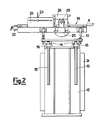
- an apparatus for correctly feeding at least one continuous strip having a shaped side outline e.g., having a sinusoidal side outline and indicated by the reference numeral 11, is installed at the inlet of a blanking or pressing machine (not shown in the figures), which receives said continuous strip 11 from an unwinding unit (not shown in the figures) on which the same strip is placed.
- the feeding apparatus comprises a framework consisting of a base 12, above which a support plane 13 is positioned, with hinge elements 14 being interposed between them.
- the support plane 13 can be tilted relatively to the base 12 thanks to the hinge elements 14, which can be respectively connected to rod elements 15, which can be moved by sliding inside respective slide and guide bushes 16 integral with the base 12, and such as to allow the rod elements 15 to slide, and to be locked in the desired position.
- rod elements 15 are provided on one side only of the apparatus, whilst on the other side the hinge elements 14 are connected to bracket elements 10 extending on the top of the base 12.
- a further support plane 17 is provided, wherein restraint and side guide elements generally indicated by the reference numeral 19, for retaining and guiding said continuous strip 11, can be positioned along cross guide slots 18.
- Said restraint and side guide elements 19 preferably have an essentially "C"-shaped cross section, are opposite to each other, and, on a lower portion thereof, are provided with a plurality of revolving elements 20, such as rollers, in order to support the opposite ends of the continous strip 11.
- the upper portion of said restraint elements has, nearly in correspondence with the vertical wall 21, a longitudinal through-slot 22, through which a sensor element 23 acts, which is suitably supported - and adjustable in position - above a vertical plate 33 integral with said restraint and side guide elements 19.
- a feed unit is positioned, which comprises a calender constituted by a lower roll 24 driven by means of a relevant motor means 25, suitably supported in 26 sideways and transversely to the further support plane 17. Coupled with, and opposite to, said lower roll 24, an upper roll 27 is positioned, which freely rotatable on a respective shaft 28, and which, at an end 29 thereof, is adjustable in height relatively to the support plane 17, and consequently relatively to the lower roll 24, so that the calibration can be changed as a function of the thickness of the continuous strip 11 being fed.
- the lower roll 24, e.g., a rubber roll, and the upper roll 27, e.g., a steel roll, constitute a pair of rolls interacting with each other, having such transversal dimensions as to occupy a minimum central portion of said continuous strip 11.
- Both the motor means 25 and the sensor elements 23 are operatively connected by means of connecting lines 30 to a monitoring and control device 31 operatively connected, through a further line 30, to the drive means of the blanking machine (not shown in the figures), so as to correlate the operation thereof.
- an invitation roller 32 for the continuous strip of material being fed is provided.
- An apparatus according to the present invention operates as follows.
- the continuous strip 11 having a shaped side outline, after being unwound and passed above the roller 32, installed at the inlet of the apparatus according to the invention, enters the restraint and side guide elements 19 supported in correspondence of longitudinal side portions by the rollers 20.
- the continuous strip 11 passes then through the pair of rolls 24 and 27, and, after exiting them, is fed to the blanking machine (not shown in the figures).
- this feed has to be carried out in a stepwise fashion, so that under the die strip portions are brought, which are perfectly trued respectively to said die.
- this stepwise progressing is carried out by means of the pair of rolls 24 and 27, or, better, by means of the actuation of the motor means 25, controlled by at least one of the sensor elements 23, such as photocells, optical fibres, and so forth, which detect a predetermined height of the sinusoid, nearly in the nearby of the crest, or of the peak of said sinusoid.
- the sensor elements 23 such as photocells, optical fibres, and so forth, which detect a predetermined height of the sinusoid, nearly in the nearby of the crest, or of the peak of said sinusoid.
- the stop command to stop the revolution of the motor-driven roll 24 is given by the first one of said sensor elements 23 which detects said preselected height, independently from the fact whether such a detection occurs in correspondence of the one side, or in correspondence of the other side, of the restraint and guide elements 19.
- the strip is not obliged to progress according to a certain direction throughout its transversal surface, and, by interacting with the vertical walls 21 of the restraint and side guide elements 19, tends to arrange itself back according to the correct axis or direction of progressing. All this occurs precisely thanks to the fact that the action of the pair of feed rolls is limited to a minimum strip portion, and gives the same strip the possibility of correctly adapting or aligning again inside the apparatus.
- the presence of the hinge elements 14, of the rod elements 15 and of the relevant slide and guide bushes 16, as well as of the bracket elements 10 makes it possible the support plane 13 to be tilted, so that an apparatus according to the present invention can be positioned at the inlet of a blanking machine operating according to an inclined arrangement, so as to operate rapidly, allowing the blanked product to exit instantaneously, and the scrap material to be wound again.
- the slotted cross guides 18 make it possible the restraint and side guide elements 19 to be moved, so as to be approached to, and spaced apart from, each other, in order that they may be adjusted and adapted in position as a function of varying maximum transversal dimensions of the continuous strip to be fed.
- an apparatus according to the present invention has to be used for processing a continuous strip having mutually parallel straight edges, a simple turning off of the sensor elements, and the prearrangement of a detector means for detecting the strip length fed in the stepwiseprogressing mode will make it possible the use change and the new operating mode of said apparatus to be accomplished immediately.
Landscapes
- Engineering & Computer Science (AREA)
- Mechanical Engineering (AREA)
- Advancing Webs (AREA)
- Registering, Tensioning, Guiding Webs, And Rollers Therefor (AREA)
- Controlling Rewinding, Feeding, Winding, Or Abnormalities Of Webs (AREA)
- Perforating, Stamping-Out Or Severing By Means Other Than Cutting (AREA)
- Specific Conveyance Elements (AREA)
- Accessories And Tools For Shearing Machines (AREA)
- Making Paper Articles (AREA)
- Press Drives And Press Lines (AREA)
- Treatment Of Fiber Materials (AREA)
- Punching Or Piercing (AREA)
- Processing And Handling Of Plastics And Other Materials For Molding In General (AREA)
- Delivering By Means Of Belts And Rollers (AREA)
- Table Devices Or Equipment (AREA)
- Distillation Of Fermentation Liquor, Processing Of Alcohols, Vinegar And Beer (AREA)
- Sheets, Magazines, And Separation Thereof (AREA)
- Finish Polishing, Edge Sharpening, And Grinding By Specific Grinding Devices (AREA)
- Details Of Cutting Devices (AREA)
- Buckles (AREA)
- Finger-Pressure Massage (AREA)
- Vessels, Lead-In Wires, Accessory Apparatuses For Cathode-Ray Tubes (AREA)
Priority Applications (1)
| Application Number | Priority Date | Filing Date | Title |
|---|---|---|---|
| AT88202222T ATE79060T1 (de) | 1987-10-19 | 1988-10-06 | Vorrichtung zum korrekten zufuehren kontinuierlicher baender mit geformter seitenflaeche zu stanzmaschinen. |
Applications Claiming Priority (2)
| Application Number | Priority Date | Filing Date | Title |
|---|---|---|---|
| IT2232687 | 1987-10-19 | ||
| IT8722326A IT1231900B (it) | 1987-10-19 | 1987-10-19 | Apparecchiatura per l'alimentazione corretta di strisce continue a profilo laterale sagomato a macchine di tranciatura |
Publications (3)
| Publication Number | Publication Date |
|---|---|
| EP0313142A2 true EP0313142A2 (de) | 1989-04-26 |
| EP0313142A3 EP0313142A3 (en) | 1989-10-18 |
| EP0313142B1 EP0313142B1 (de) | 1992-08-05 |
Family
ID=11194713
Family Applications (1)
| Application Number | Title | Priority Date | Filing Date |
|---|---|---|---|
| EP88202222A Expired - Lifetime EP0313142B1 (de) | 1987-10-19 | 1988-10-06 | Vorrichtung zum korrekten Zuführen kontinuierlicher Bänder mit geformter Seitenfläche zu Stanzmaschinen |
Country Status (25)
| Country | Link |
|---|---|
| US (1) | US4925079A (de) |
| EP (1) | EP0313142B1 (de) |
| JP (1) | JPH01148429A (de) |
| KR (1) | KR920009814B1 (de) |
| CN (1) | CN1015331B (de) |
| AT (1) | ATE79060T1 (de) |
| AU (1) | AU605369B2 (de) |
| BR (1) | BR8805385A (de) |
| CA (1) | CA1317327C (de) |
| DE (1) | DE3873475T2 (de) |
| DK (1) | DK579388A (de) |
| ES (1) | ES2034166T3 (de) |
| FI (1) | FI884786A7 (de) |
| GR (1) | GR3005544T3 (de) |
| IL (1) | IL88023A (de) |
| IT (1) | IT1231900B (de) |
| MA (1) | MA21405A1 (de) |
| MX (1) | MX169779B (de) |
| NO (1) | NO172839C (de) |
| NZ (1) | NZ226432A (de) |
| PL (1) | PL158438B1 (de) |
| RU (1) | RU1828417C (de) |
| TN (1) | TNSN88110A1 (de) |
| TR (1) | TR24103A (de) |
| ZA (1) | ZA887512B (de) |
Families Citing this family (9)
| Publication number | Priority date | Publication date | Assignee | Title |
|---|---|---|---|---|
| DE4136209C1 (de) * | 1991-11-02 | 1993-06-09 | Rieter Ingolstadt Spinnereimaschinenbau Ag, 8070 Ingolstadt, De | |
| US5488467A (en) * | 1994-06-24 | 1996-01-30 | Rjs, Inc. | Laser printer paper handling system |
| DK177820B1 (da) * | 2009-06-12 | 2014-08-18 | Skov As | Fremgangsmåde til styring af luftindtag og anvendelse |
| CN102530543A (zh) * | 2012-02-24 | 2012-07-04 | 太仓康茂电子有限公司 | 一种间歇自动送料装置 |
| KR101377499B1 (ko) * | 2012-04-26 | 2014-03-26 | 현대제철 주식회사 | 슬라브 지지장치 |
| CN102794372A (zh) * | 2012-08-13 | 2012-11-28 | 尤海江 | 一种配合冲床使用的数控自动送料机及其方法 |
| CN103447406B (zh) * | 2013-08-16 | 2016-05-25 | 广东华田电器有限公司 | 浮动式板材输送装置 |
| CN104097343B (zh) * | 2014-06-17 | 2018-10-16 | 张科 | 一种开式可倾压力机 |
| CN105033086A (zh) * | 2015-09-17 | 2015-11-11 | 成都爆米花信息技术有限公司 | 一种滚动式钢带自动送料机 |
Family Cites Families (16)
| Publication number | Priority date | Publication date | Assignee | Title |
|---|---|---|---|---|
| US2250138A (en) * | 1940-02-01 | 1941-07-22 | Morgan Construction Co | Apparatus for handling elongated material |
| US2896505A (en) * | 1955-12-21 | 1959-07-28 | Nat Electronics Distributors I | Automatic photo printing machine |
| US3026012A (en) * | 1960-05-13 | 1962-03-20 | Murray G Clay | Wire guide for spring-coiling machines |
| US3128548A (en) * | 1960-09-26 | 1964-04-14 | Peter A Zelisko | Method and means for processing coiled stock into containers |
| US3665794A (en) * | 1970-03-23 | 1972-05-30 | Littell Machine Co F J | Apparatus for positioning scroll shaped metal strips |
| US3837549A (en) * | 1970-11-27 | 1974-09-24 | K Sengewald | Dispenser for carrying bags or the like |
| US3782616A (en) * | 1972-02-18 | 1974-01-01 | Us Postage Box Co | Stamp dispensing apparatus |
| US3839934A (en) * | 1973-04-27 | 1974-10-08 | Krakower Samanowitz & Goldman | Automatic tape-feed, indexing and cutting mechanism |
| DE2407848C2 (de) * | 1974-02-19 | 1985-10-17 | Jagenberg-Werke AG, 4000 Düsseldorf | Vorrichtung zum Einebnen und ebenflächigen Weiterführen von einer oder mehreren in Papierverarbeitungsmaschinen freischwebend geführten Materialbahnen |
| US4158429A (en) * | 1977-03-28 | 1979-06-19 | Honshyuseishi Kabushiki Kaishya | Apparatus for feeding elongate sheet materials |
| US4341155A (en) * | 1980-10-03 | 1982-07-27 | Drustar, Inc. | Custom label printer |
| US4420107A (en) * | 1982-02-18 | 1983-12-13 | National Semiconductor Corp. | Lead frame advance system |
| SE435266B (sv) * | 1983-02-10 | 1984-09-17 | Tetra Pak Int | Sett att frammata en monsterforsedd materialbana samt anordning for genomforande av nemnda sett |
| GB8420343D0 (en) * | 1984-08-10 | 1984-09-12 | Workman J | Metal pressing and stamping |
| US4771928A (en) * | 1986-05-09 | 1988-09-20 | Takanori Okada | Towel fabric processing device |
| US4809188A (en) * | 1986-10-17 | 1989-02-28 | Spartanics, Ltd. | Strip feeding and control system |
-
1987
- 1987-10-19 IT IT8722326A patent/IT1231900B/it active
-
1988
- 1988-10-03 NZ NZ226432A patent/NZ226432A/xx unknown
- 1988-10-05 CA CA000579416A patent/CA1317327C/en not_active Expired - Fee Related
- 1988-10-06 AT AT88202222T patent/ATE79060T1/de not_active IP Right Cessation
- 1988-10-06 ZA ZA887512A patent/ZA887512B/xx unknown
- 1988-10-06 DE DE8888202222T patent/DE3873475T2/de not_active Expired - Fee Related
- 1988-10-06 EP EP88202222A patent/EP0313142B1/de not_active Expired - Lifetime
- 1988-10-06 ES ES198888202222T patent/ES2034166T3/es not_active Expired - Lifetime
- 1988-10-11 US US07/256,027 patent/US4925079A/en not_active Expired - Fee Related
- 1988-10-12 IL IL88023A patent/IL88023A/xx not_active IP Right Cessation
- 1988-10-14 MA MA21645A patent/MA21405A1/fr unknown
- 1988-10-14 JP JP63257380A patent/JPH01148429A/ja active Pending
- 1988-10-14 TR TR88/0714A patent/TR24103A/xx unknown
- 1988-10-17 KR KR1019880013519A patent/KR920009814B1/ko not_active Expired
- 1988-10-17 FI FI884786A patent/FI884786A7/fi not_active IP Right Cessation
- 1988-10-17 MX MX013444A patent/MX169779B/es unknown
- 1988-10-17 AU AU23909/88A patent/AU605369B2/en not_active Ceased
- 1988-10-18 BR BR8805385A patent/BR8805385A/pt not_active IP Right Cessation
- 1988-10-18 CN CN88108215A patent/CN1015331B/zh not_active Expired
- 1988-10-18 RU SU884356708A patent/RU1828417C/ru active
- 1988-10-18 NO NO884627A patent/NO172839C/no unknown
- 1988-10-18 DK DK579388A patent/DK579388A/da not_active Application Discontinuation
- 1988-10-19 PL PL1988275370A patent/PL158438B1/pl unknown
- 1988-10-19 TN TNTNSN88110A patent/TNSN88110A1/fr unknown
-
1992
- 1992-08-27 GR GR920401873T patent/GR3005544T3/el unknown
Also Published As
Similar Documents
| Publication | Publication Date | Title |
|---|---|---|
| EP0313142B1 (de) | Vorrichtung zum korrekten Zuführen kontinuierlicher Bänder mit geformter Seitenfläche zu Stanzmaschinen | |
| US4354788A (en) | Automatic system for the formation and distribution of layers of groups of sheets | |
| US5023976A (en) | Feed table of a drawframe arrangement | |
| US5673837A (en) | Apparatus for the high speed stacking of paper sheets | |
| JP2749556B2 (ja) | 金属化画像をシート要素に転写する機械における金属化ベルトの移送装置 | |
| CA2070950C (en) | Method and apparatus for making a steel joist | |
| EP1462177B1 (de) | Überführungseinrichtung für den Anfang einer Folienbahn oder eines Folienrestgitters von einer Thermoformmaschine zu einer Schneidmühle und Verfahren zum Betreiben der Überführungseinrichtung | |
| EP0538526A1 (de) | Vorrichtung zum Richten einer Kante eines rechteckigen Stück-Tuch | |
| CN113828705A (zh) | 具有钢筋自动拉直及等尺剪切功能的剪切机 | |
| GB1586546A (en) | Apparatus for forming blocks of flattened bags or stackable elements of plastics film material | |
| JP4868481B2 (ja) | 横方向切断機からシートを処理する機械へシートを搬送するための装置 | |
| CN214031145U (zh) | 一种全自动模切断张机 | |
| JPH05146911A (ja) | 格子構造体から選択可能な長さの格子片を分断するための切断設備 | |
| EP1041237A1 (de) | Verfahren und Anlage zur automatischen Krümmungsanpassung von Jalousielamelle | |
| CN113879896B (zh) | 一种切割设备 | |
| EP0934784A1 (de) | Zuführvorrichtung für Band aus Metall | |
| KR102117778B1 (ko) | 시트 요소 처리 머신에서의 이중 시트들을 검출하는 검출 시스템 및 시트 요소 처리 머신 | |
| US20060113165A1 (en) | Method and apparatus for processing printed articles | |
| CN215124747U (zh) | 一种卷材上料设备 | |
| KR100890221B1 (ko) | 전자가속기를 이용한 시트가공용 시트의 연속 공급 및권취장치 | |
| EP0781721A2 (de) | Maschine zum Auslegen von laminaren Produkten | |
| EP0201120B2 (de) | Vorrichtung zur automatischen Beschickung einer stromabwärts eines Kühlbettes angeordneten mehrspurigen Richtmaschine | |
| CN220536710U (zh) | 一种覆膜机除尘用宽幅输送装置 | |
| ITVE980006A1 (it) | Alimentatore perfezionato di nastro di lamiera | |
| CN214779754U (zh) | 收卷分切机 |
Legal Events
| Date | Code | Title | Description |
|---|---|---|---|
| PUAI | Public reference made under article 153(3) epc to a published international application that has entered the european phase |
Free format text: ORIGINAL CODE: 0009012 |
|
| AK | Designated contracting states |
Kind code of ref document: A2 Designated state(s): AT BE CH DE ES FR GB GR LI LU NL SE |
|
| PUAL | Search report despatched |
Free format text: ORIGINAL CODE: 0009013 |
|
| AK | Designated contracting states |
Kind code of ref document: A3 Designated state(s): AT BE CH DE ES FR GB GR LI LU NL SE |
|
| 17P | Request for examination filed |
Effective date: 19900223 |
|
| 17Q | First examination report despatched |
Effective date: 19910220 |
|
| RAP1 | Party data changed (applicant data changed or rights of an application transferred) |
Owner name: L.M. LAMINATI METALLICI S.P.A. |
|
| GRAA | (expected) grant |
Free format text: ORIGINAL CODE: 0009210 |
|
| AK | Designated contracting states |
Kind code of ref document: B1 Designated state(s): AT BE CH DE ES FR GB GR LI LU NL SE |
|
| REF | Corresponds to: |
Ref document number: 79060 Country of ref document: AT Date of ref document: 19920815 Kind code of ref document: T |
|
| REF | Corresponds to: |
Ref document number: 3873475 Country of ref document: DE Date of ref document: 19920910 |
|
| ET | Fr: translation filed | ||
| REG | Reference to a national code |
Ref country code: GR Ref legal event code: FG4A Free format text: 3005544 |
|
| REG | Reference to a national code |
Ref country code: ES Ref legal event code: FG2A Ref document number: 2034166 Country of ref document: ES Kind code of ref document: T3 |
|
| PLBE | No opposition filed within time limit |
Free format text: ORIGINAL CODE: 0009261 |
|
| STAA | Information on the status of an ep patent application or granted ep patent |
Free format text: STATUS: NO OPPOSITION FILED WITHIN TIME LIMIT |
|
| 26N | No opposition filed | ||
| EPTA | Lu: last paid annual fee | ||
| PGFP | Annual fee paid to national office [announced via postgrant information from national office to epo] |
Ref country code: LU Payment date: 19940901 Year of fee payment: 7 |
|
| PGFP | Annual fee paid to national office [announced via postgrant information from national office to epo] |
Ref country code: FR Payment date: 19940915 Year of fee payment: 7 |
|
| PGFP | Annual fee paid to national office [announced via postgrant information from national office to epo] |
Ref country code: CH Payment date: 19940919 Year of fee payment: 7 |
|
| PGFP | Annual fee paid to national office [announced via postgrant information from national office to epo] |
Ref country code: GR Payment date: 19940921 Year of fee payment: 7 |
|
| PGFP | Annual fee paid to national office [announced via postgrant information from national office to epo] |
Ref country code: GB Payment date: 19940927 Year of fee payment: 7 |
|
| PGFP | Annual fee paid to national office [announced via postgrant information from national office to epo] |
Ref country code: BE Payment date: 19941012 Year of fee payment: 7 |
|
| PGFP | Annual fee paid to national office [announced via postgrant information from national office to epo] |
Ref country code: ES Payment date: 19941014 Year of fee payment: 7 Ref country code: AT Payment date: 19941014 Year of fee payment: 7 |
|
| PGFP | Annual fee paid to national office [announced via postgrant information from national office to epo] |
Ref country code: SE Payment date: 19941018 Year of fee payment: 7 Ref country code: DE Payment date: 19941018 Year of fee payment: 7 |
|
| PGFP | Annual fee paid to national office [announced via postgrant information from national office to epo] |
Ref country code: NL Payment date: 19941031 Year of fee payment: 7 |
|
| EAL | Se: european patent in force in sweden |
Ref document number: 88202222.1 |
|
| PG25 | Lapsed in a contracting state [announced via postgrant information from national office to epo] |
Ref country code: LU Free format text: LAPSE BECAUSE OF NON-PAYMENT OF DUE FEES Effective date: 19951006 Ref country code: GB Effective date: 19951006 Ref country code: AT Effective date: 19951006 |
|
| PG25 | Lapsed in a contracting state [announced via postgrant information from national office to epo] |
Ref country code: SE Effective date: 19951007 Ref country code: ES Free format text: LAPSE BECAUSE OF THE APPLICANT RENOUNCES Effective date: 19951007 |
|
| PG25 | Lapsed in a contracting state [announced via postgrant information from national office to epo] |
Ref country code: LI Effective date: 19951031 Ref country code: CH Effective date: 19951031 Ref country code: BE Effective date: 19951031 |
|
| BERE | Be: lapsed |
Owner name: LAMINATI METALLICI S.P.A. LM Effective date: 19951031 |
|
| PG25 | Lapsed in a contracting state [announced via postgrant information from national office to epo] |
Ref country code: GR Free format text: THE PATENT HAS BEEN ANNULLED BY A DECISION OF A NATIONAL AUTHORITY Effective date: 19960430 |
|
| PG25 | Lapsed in a contracting state [announced via postgrant information from national office to epo] |
Ref country code: NL Effective date: 19960501 |
|
| GBPC | Gb: european patent ceased through non-payment of renewal fee |
Effective date: 19951006 |
|
| REG | Reference to a national code |
Ref country code: CH Ref legal event code: PL |
|
| PG25 | Lapsed in a contracting state [announced via postgrant information from national office to epo] |
Ref country code: FR Effective date: 19960628 |
|
| REG | Reference to a national code |
Ref country code: GR Ref legal event code: MM2A Free format text: 3005544 |
|
| EUG | Se: european patent has lapsed |
Ref document number: 88202222.1 |
|
| PG25 | Lapsed in a contracting state [announced via postgrant information from national office to epo] |
Ref country code: DE Effective date: 19960702 |
|
| NLV4 | Nl: lapsed or anulled due to non-payment of the annual fee |
Effective date: 19960501 |
|
| REG | Reference to a national code |
Ref country code: FR Ref legal event code: ST |
|
| REG | Reference to a national code |
Ref country code: ES Ref legal event code: FD2A Effective date: 19991007 |