EP0313394A2 - Verfahren und Einrichtung zur Informationsaufzeichnung und -wiedergabe - Google Patents
Verfahren und Einrichtung zur Informationsaufzeichnung und -wiedergabe Download PDFInfo
- Publication number
- EP0313394A2 EP0313394A2 EP88309931A EP88309931A EP0313394A2 EP 0313394 A2 EP0313394 A2 EP 0313394A2 EP 88309931 A EP88309931 A EP 88309931A EP 88309931 A EP88309931 A EP 88309931A EP 0313394 A2 EP0313394 A2 EP 0313394A2
- Authority
- EP
- European Patent Office
- Prior art keywords
- information
- recording
- light
- tracking
- photosensor
- Prior art date
- Legal status (The legal status is an assumption and is not a legal conclusion. Google has not performed a legal analysis and makes no representation as to the accuracy of the status listed.)
- Granted
Links
- 238000000034 method Methods 0.000 title claims abstract description 19
- 230000003287 optical effect Effects 0.000 claims abstract description 47
- 230000001678 irradiating effect Effects 0.000 claims abstract description 6
- 238000010586 diagram Methods 0.000 description 16
- 201000009310 astigmatism Diseases 0.000 description 3
- 230000015572 biosynthetic process Effects 0.000 description 3
- 230000007423 decrease Effects 0.000 description 3
- 238000003786 synthesis reaction Methods 0.000 description 3
- 230000000694 effects Effects 0.000 description 2
- 238000001579 optical reflectometry Methods 0.000 description 2
- 230000005540 biological transmission Effects 0.000 description 1
- 230000003247 decreasing effect Effects 0.000 description 1
- 238000002310 reflectometry Methods 0.000 description 1
- 239000004065 semiconductor Substances 0.000 description 1
- 238000010408 sweeping Methods 0.000 description 1
Images


Classifications
-
- G—PHYSICS
- G11—INFORMATION STORAGE
- G11B—INFORMATION STORAGE BASED ON RELATIVE MOVEMENT BETWEEN RECORD CARRIER AND TRANSDUCER
- G11B7/00—Recording or reproducing by optical means, e.g. recording using a thermal beam of optical radiation by modifying optical properties or the physical structure, reproducing using an optical beam at lower power by sensing optical properties; Record carriers therefor
- G11B7/08—Disposition or mounting of heads or light sources relatively to record carriers
- G11B7/09—Disposition or mounting of heads or light sources relatively to record carriers with provision for moving the light beam or focus plane for the purpose of maintaining alignment of the light beam relative to the record carrier during transducing operation, e.g. to compensate for surface irregularities of the latter or for track following
- G11B7/0938—Disposition or mounting of heads or light sources relatively to record carriers with provision for moving the light beam or focus plane for the purpose of maintaining alignment of the light beam relative to the record carrier during transducing operation, e.g. to compensate for surface irregularities of the latter or for track following servo format, e.g. guide tracks, pilot signals
-
- G—PHYSICS
- G11—INFORMATION STORAGE
- G11B—INFORMATION STORAGE BASED ON RELATIVE MOVEMENT BETWEEN RECORD CARRIER AND TRANSDUCER
- G11B7/00—Recording or reproducing by optical means, e.g. recording using a thermal beam of optical radiation by modifying optical properties or the physical structure, reproducing using an optical beam at lower power by sensing optical properties; Record carriers therefor
- G11B7/002—Recording, reproducing or erasing systems characterised by the shape or form of the carrier
- G11B7/0033—Recording, reproducing or erasing systems characterised by the shape or form of the carrier with cards or other card-like flat carriers, e.g. flat sheets of optical film
-
- G—PHYSICS
- G11—INFORMATION STORAGE
- G11B—INFORMATION STORAGE BASED ON RELATIVE MOVEMENT BETWEEN RECORD CARRIER AND TRANSDUCER
- G11B7/00—Recording or reproducing by optical means, e.g. recording using a thermal beam of optical radiation by modifying optical properties or the physical structure, reproducing using an optical beam at lower power by sensing optical properties; Record carriers therefor
- G11B7/12—Heads, e.g. forming of the optical beam spot or modulation of the optical beam
- G11B7/13—Optical detectors therefor
-
- G—PHYSICS
- G11—INFORMATION STORAGE
- G11B—INFORMATION STORAGE BASED ON RELATIVE MOVEMENT BETWEEN RECORD CARRIER AND TRANSDUCER
- G11B7/00—Recording or reproducing by optical means, e.g. recording using a thermal beam of optical radiation by modifying optical properties or the physical structure, reproducing using an optical beam at lower power by sensing optical properties; Record carriers therefor
- G11B7/12—Heads, e.g. forming of the optical beam spot or modulation of the optical beam
- G11B7/14—Heads, e.g. forming of the optical beam spot or modulation of the optical beam specially adapted to record on, or to reproduce from, more than one track simultaneously
Definitions
- This invention relates to a method and an apparatus for recording (writing) or reproducing (reading) information by using optical information-recording media, such as optical cards, optical disks or the like, and more particularly relates to a method and an apparatus for recording in and reproducing from card-like optical information recording media, i.e., optical cards, in which tracks for the purpose of tracking are provided.
- write-once type optical cards in which it is possible to record only once, and to reproduce a plurality of times are well known.
- information is recorded as a row of pits (information tracks) which are optically detectable, by focusing a light beam which is modulated according to the information to be recorded into a minute light spot by a lens, and by irradiating and scanning the minute light spot on an information-recording region of the optical card.
- the present invention has been accomplished in order to solve such a disadvantage. It is an object of the present invention to provide a method and an apparatus for recording on and reproducing from an optical card in which a plurality of information tracks are formed in an information-recording region thereof to increase the recording capacity.
- the present invention provides: a method for recording and reproducing information comprising irradiating a light spot for recording and reproducing information and a plurality of light spots for tracking on an information-recording region of an optical information-recording medium including tracks for guiding, projecting reflected beams from the optical information-recording medium due to said light spot for recording and reproducing information and plurality of light spots for tracking on a photosensor, and selecting two outputs from a plurality of electrical outputs for tracking from said photosensor to provide tracking-control signals; and an apparatus for recording and reproducing information comprising a light source for projecting at least three light spots for information read-out and for tracking on an optical information-recording medium including tracks for guiding, a photosensor for detecting information, plural pairs of photosensors for following tracks which are located at predetermined positions relative to the photosensor for detecting information, switching connectors to which a pair of the photosensors for following tracks are connected on one side and on another side relative to said photosensor for
- a plurality of light spots for recording and reproducing information and for tracking are irradiated on the above-described optical information-recording medium.
- Information is therefore recorded in the information tracks on the optical information-recording medium.
- On the optical information-recording medium a plurality of information tracks are formed between two tracks for guiding, the reflected light from each of these tracks is detected by a photosensor, respectively, and the information is reproduced.
- These photosensors consist of a photosensor for detecting information and plural pairs of photosensors for following tracks.
- a pair of photosensors for following tracks are selected, and tracking control is performed by using signals from the selected pair of photosensors.
- the information-recording track to be read by the photosensor for detecting information which is disposed at a predetermined position relationship relative to these pair of photosensors is automatically determined.
- the photosensor for detecting information reads out information from some other information track.
- a method for recording and reproducing information according to the present invention has a great effect such that recording capacity can be increased several times without modifying the optical cards.
- tracks for guiding are formed by means, such as exposure, development or the like by photographic technique, and hence the line width of a track itself cannot be very narrow and the variance in the line width is also large. Consequently, a write-once type optical card (briefly termed an optical card hereafter) has hitherto been formed, for example, as shown in FIG. 12.
- tracks 2 for guiding which have, for example, a reduced optical reflectivity are provided on an optical card 1, and information is to be recorded on an information-recording region 3 which is provided between the tracks 2 for guiding.
- the line width of tracks 2 for guiding is 3 ⁇ m
- the line width of the information-recording region 3 is 17 ⁇ m
- the track pitch is about 20 ⁇ m.
- FIG. 13 is an enlarged diagram of a part of FIG. 12, in which information pits 4 are recorded on a track on a center line 5 of the information-recording region 3 to form an information track 6 (a region which is placed between two dotted lines).
- the information pits 4 have dimensions with a diameter of, for example, 5 ⁇ m, and optical reflectivity thereof becomes smaller than that of other regions.
- An optical card has a feature, in general, that it has a recording capacity larger than a magnetic card or the like, but the conventional recording method as shown in FIG. 13 does not fully utilize the feature.
- the dimensions of an information pit should be small.
- making the information pits smaller is not very effective for the increase of recording capacity because of a limitation in the dimensions of a track pitch by using photographic techniques. That is, there exists a disadvantage that even when information pits are made smaller, an extremely large portion remains which is not utilized for information recording within the information-recording region 3.
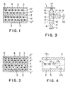
- FIGS. 1 and 2 show embodiments in which a plurality of information tracks are formed on optical cards to increase the recording capacity according to the present invention.
- FIG. 1 two information tracks 6′ and 6 ⁇ are formed on an information recording region 3, and thus the recording capacity is double that of the conventional case of using only one track.
- FIG. 2 three information tracks 6, 6′ and 6 ⁇ are formed on the information recording region 3 to increase the recording capacity three times than the conventional case.
- FIG. 3 is a diagram showing a configuration of an optical head for recording and reproducing for a plurality of information tracks used for embodying the method of the present invention.
- a light beam 8 irradiated from a light source 7, such as a semiconductor laser or the like is converted into a parallel beam 10 by a collimating lens 9 and is then projected on a diffraction grating 11 to produce a plurality of, i.e., 0-order and ⁇ n-order (n is 1, 2, 3, ----) transmitting diffraction lights.
- the plurality of transmitting diffraction lights i.e., plural beams 12 projected on a beam splitter 13, and plural beams 15 which have transmitted through a semitransparent film 14 (the ratio of the intensity of transmitting light to reflected light may be other than 1) of the beam splitter 13, are focused into plural minute light spots 17 (termed light spots hereafter) by a focusing lens 16 to irradiate upon the information-recording region 3 of the optical card 1.
- a high output-power light in which the light source 7 is modified by information signals is used for recording information, and a continuous low output-power light is used for reproducing information.
- Plural reflected beams from the optical card 1 move backward through the focusing lens 16 and become nearly parallel beams (they sometimes become slightly converging beams or diverging beams depending on focusing situation), are reflected by the semi-transparent film 14 of the beam splitter 13 to be directed towards the right, are reduced into smaller beams by a light-receiving lens 18, and then reach a photodiode 20 through a cylindrical lens 19. From the photodiode 20, information signals, focusing signals indicating focusing situations of the light spots 17 and tracking signals indicating the position of the light spots 17 relative to the tracks 2 for guiding are obtained.
- the light-receiving lens 18 is an optical unit for reducing plural reflected parallel beams into smaller beams
- the cylindrical lens 19 is an optical unit for producing astigmatism to obtain focusing-control signals.
- FIG. 4 shows three light spots 17a, 17b and 17c which are to be irradiated upon the information-recording region 3 of the optical card 1.
- the light spot 17a is due to the 0-order diffraction light of the diffraction grating 11
- the light spots 17b and 17c are due to + 1st-order diffraction light and 1st-order diffraction light of the diffraction grating 11, respectively.
- they are disposed in positions which are shifted in oblique directions for the convenience of read-out.
- the light spot 17a forms information pits 4 with a high light energy in the case of recording information, and scans the information tracks 6 with a low light energy and reads out the information pits 4 from a change in the reflectivity of light in the case of reproducing information.
- the light spots 17b and 17c are for tracking purposes. They have a light energy smaller than the light spot 17a, and partly irradiate tracks 2 for guiding, respectively.
- the light spot 17a scans the information tracks 6 (the situation is relatively the same when the optical card is moved)
- the light spot 17a usually runs off from an information track 6 due to causes, such as mechanical error or the like, and crosses many information tracks 6 to make it impossible to record and reproduce information.
- a servo-control is performed for the motor so that the light spot 17a correctly follows and scans the information track 6.
- the light spots 17b and 17c are deviated to the same direction by the same amount.
- the light spot 17a is slightly deviated to a direction of an arrow 21
- a portion of the track 2 for guiding which the light spot 17b irradiates increases, hence the intensity of reflected light is decreased
- a portion of the track 2 for guiding which the light spot 17c irradiates decreases, hence the intensity of reflected light is increased.
- the reflected beam spot 22a due to the light spot 17a is projected on the photodiode 20a, which is one of the four photodiodes divided from the photodiode 20, to produce information signals and focusing-control signals.
- FIG. 6 shows an embodiment in which the information track 6′ is recorded and reproduced in the information-recording region 3.
- the light spot 17a due to the 0-order diffraction light, the light spot 17b due to the + 1st-order diffraction light and the light spot 17e due to the - 2nd-order diffraction light of the diffraction grating 11 are irradiated.
- the light spot 17c and the like also irradiate, but the explanation thereof will be omitted because they have no direct relationship with operations in this embodiment.
- the photodiode 20 is divided into eight elements as shown in FIG. 8.
- the reflected beam spots 22b and 22e due to the light spots 17b and 17e are projected on the photodiodes 20b and 20e, respectively, and switches 23 and 24 are turned towards a terminal a.
- the light spot 17a can follow and scan the information track 6′.
- FIG. 8 shows an embodiment in which the information track 6 ⁇ is recorded and reproduced.
- the light spot 17a due to the 0-order diffraction light, the light spot 17d due to the + 2nd-order diffraction light and the light spot 17c due to the - 1st-order diffraction light or the like of the diffraction grating 11 are irradiated.
- the photodiode 20 is as already shown in FIG. 7.
- the reflected beam spots 22d and 22c due to the light spots 17d and 17c are projected on the photodiodes 20d and 20c, respectively, and the switches 23 and 24 are turned towards a terminal b.
- the light spot 17a can follow and scan the information track 6 ⁇ .
- FIG. 9 shows an embodiment in which the three information tracks 6, 6′ and 6 ⁇ are recorded and reproduced in the information-recording region 3.
- all embodiments are simultaneously shown as a whole, contrary to FIGS. 6 and 8 in which each embodiment has been shown separately.
- the light spot 17a due to the 0-order diffraction light, the light spot 17d due to the + 2nd-order diffraction light, the light spot 17e due to the - 2nd-order diffraction light or the like of the diffraction grating 11 are irradiated on the information-recording region 3.
- the photodiode 20 is divided into 10 elements as shown in FIG. 10.
- the reflected beam spots 22d and 22e due to the light spots 17d and 17e are projected on the photodiodes 20d and 20e, respectively, and the switches 23 and 24 are turned towards the terminal a.
- Ed an electrical output from the photodiode 20d
- Ee is an electrical output from the photodiode 20e.
- the light spot 17a due to the 0-order diffraction light, the light spot 17b due to the + 1st-order diffraction light, the light spot 17g due to the -3rd-order diffraction light or the like of the diffraction grating 11 are irradiated upon the information-recording region 3.
- the reflected beam spots 22b and 22g due to the light spots 17b and 17g are projected on the photodiodes 20b and 20g, respectively, and the switches 23 and 24 are turned towards the terminal b.
- the light spot 17a can follow and scan the information track 6′.
- the light spots 17a, 17f, 17c or the like due to the 0-order diffraction light, the + 3rd-order diffraction light, the - 1st-order diffraction light or the like of the diffraction grating 11, respectively, are irradiated upon the information-recording region 3.
- the reflected beam spots 22f and 22c due to the light spots 17f and 17c are projected on the photodiodes 20f and 20c, respectively, and the switches 23 and 24 are turned towards a terminal c.
- the light spot 17a can follow and scan the information track 6 ⁇ .
- the two light spots for tracking irradiate an end portion of the information-recording region 3 as well as a part of the tracks 2 for guiding
- these two light spots for tracking may be set so that they irradiate the adjacent information-recording region 3 as well as part of the tracks 2 for guiding. That is, the embodiment in FIG. 6 may be set as shown in FIG. 11.
- the light spots 17b and 17e are not on the information-recording region 3 which includes the information tracks 6′ and 6 ⁇ , but are on end portions of the adjacent information-recording regions 3′, respectively.
- the electrical output Eb from the photodiode 20b and the electrical output Ee from the photodiode 20e shown in FIG. 7 are opposite in phase compared with the embodiment in FIG. 6.
- the phase of the differential output 25 in FIG. 7 becomes reverse in phase, and it is necessary to operate an amplifier which amplifies the differential output 25 by reversing the polarity.
- the setting of irradiation of the light spots for tracking on the adjacent information-recording regions 3′ as described above is also applicable to the embodiments in FIGS. 8 and 9.
- the light spots for tracking are operated by partially irradiating a track 2 for guiding which is nearest to the light spot 17a for information, but the track 2 for guiding to be irradiated is not necessarily the nearest track for guiding; it may be an adjacent track for guiding or an adjacent track but one for guiding.
- the present invention it is possible to record and reproduce two information tracks by using the light spot 17a due to the 0-order diffraction light and the light spots 17b and 17e, 17d and 17c due to the diffraction lights of up to ⁇ 2nd-order of the diffraction grating 11, and three information tracks by using the light spots 17d and 17e, 17b and 17g, 17f and 17c due to the diffraction lights of up to ⁇ 3rd-order diffraction lights, and further four or more information tracks by using the light spots due to the diffraction lights of ⁇ 4th-order or more.
- the number of the information tracks 6 to be selected for recording and reproducing in the information-recording region 3 depends on the setting angle of the diffraction grating 11. That is, the number of the information-recording tracks 6 is determined by the light spots, forming the order which diffraction lights are to partially irradiate on the tracks 2 for guiding in order to be operated for tracking purpose, by adjusting an angle formed between a line which links the light spots 17a, 17b, 17c and the like and the tracks 2 for guiding.
- the light spot 17a is automatically guided on the information track where information is to be recorded and reproduced by a mere switching of the switches 23 and 24. This is performed as follows.
- the light spot 17 scans the information-recording region 3, it crosses the tracks 2 for guiding due to causes, such as mechanical error or the like. At the moment of crossing, two outputs from the photodiode 20 become equal, and tracking servo operates to make the point at which the outputs become equal to a stable point.
- the light spot 17 may be slightly swept in a direction perpendicular to the tracks 2 for guiding.
- the focusing lens 16 is driven in a direction perpendicular to the tracks 2 for guiding in the optical card 1 by an electromagnetic force in most cases. This method may be applied to the embodiments of the present invention.
- the differential output 25 in FIGS. 5, 7 and 10 may be properly amplified, and the output thereof may be applied to a focusing lens-driving coil of a tracking-drive system with a polarity so as to form a negative feedback loop. It will be noted that the sweeping of the light spot 17, when the light spot 17a is guided in a short period of time as described above, can be achieved by applying sweep signals to the focusing lens-driving coil.
- the configuration of the optical head shown in FIG. 3 shows an example, and hence it will be apparent that the application of the present invention is not limited to the configuration in FIG. 3.
- the kind or location of an optical unit may be modified:
- the beam splitter 13 in FIG. 3 may be modified, for example, into a combination of a polarizing prism and a 1/4 wavelength plate; or a location of the collimating lens 9 may be modified to a portion between the beam splitter 13 and the focusing lens 16.
- a method other than the astigmatism method may be used.
- a phase grating is generally used in order to decrease a loss of transmission light. It is also desirable to properly select a relationship between amplitude and phase, and to set so that the intensity of the 0-order diffraction light is large, the intensities of diffraction lights of other than 0-order are small (for example, a few fractions of the intensity of the 0-order diffraction light), and the intensities of diffraction lights of other than 0-order to be used are nearly equal in intensity to each other.
- the photodiode 20 is divided into elements the number of which differs according to the number of the information tracks 6.
- the photodiode 20 is divided into six elements when there is one information track 6, divided into eight elements when there are two information tracks 6, divided into ten elements when there are three information tracks 6 and so forth, i.e., the number of division increases by two for each increment in the number of information tracks 6.
- the switches 23 and 24 may be interlocked, and it is necessary to provide as many switching terminals as the number of information tracks 6. It is needless to say that either mechanical switches or electronic switches are applicable.
- write-once type optical cards have been exemplified and explained in detail as the optical information-recording media.
- the present invention is not limited, however, to write-once type optical cards, and is also applicable to erasable type optical cards or the like, and is further applicable to optical disks or the like.
Landscapes
- Physics & Mathematics (AREA)
- Optics & Photonics (AREA)
- Optical Recording Or Reproduction (AREA)
Applications Claiming Priority (2)
| Application Number | Priority Date | Filing Date | Title |
|---|---|---|---|
| JP62266212A JPH01125732A (ja) | 1987-10-23 | 1987-10-23 | 情報の記録再生方法および装置 |
| JP266212/87 | 1987-10-23 |
Publications (3)
| Publication Number | Publication Date |
|---|---|
| EP0313394A2 true EP0313394A2 (de) | 1989-04-26 |
| EP0313394A3 EP0313394A3 (en) | 1989-08-16 |
| EP0313394B1 EP0313394B1 (de) | 1994-04-06 |
Family
ID=17427817
Family Applications (1)
| Application Number | Title | Priority Date | Filing Date |
|---|---|---|---|
| EP88309931A Expired - Lifetime EP0313394B1 (de) | 1987-10-23 | 1988-10-21 | Verfahren und Einrichtung zur Informationsaufzeichnung und -wiedergabe |
Country Status (5)
| Country | Link |
|---|---|
| US (1) | US5184340A (de) |
| EP (1) | EP0313394B1 (de) |
| JP (1) | JPH01125732A (de) |
| CA (1) | CA1324667C (de) |
| DE (1) | DE3888915T2 (de) |
Cited By (7)
| Publication number | Priority date | Publication date | Assignee | Title |
|---|---|---|---|---|
| EP0336328A3 (de) * | 1988-04-04 | 1991-01-09 | Nippon Conlux Co., Ltd. | Gerät zur optischen Aufnahme und Wiedergabe von Information |
| EP0441435A1 (de) * | 1990-02-06 | 1991-08-14 | Koninklijke Philips Electronics N.V. | Optische Abtastvorrichtung mit mehreren Abtastflecken |
| US5754505A (en) * | 1993-04-26 | 1998-05-19 | Sony Corporation | Optical disc system with an optical disc having at least one channel of a multiple channel signal recorded on each side of a wobbling groove |
| WO2005024798A3 (en) * | 2003-09-11 | 2005-07-28 | Koninkl Philips Electronics Nv | Tracking method, recording means and a recorder for an optical disc |
| WO2006131858A1 (en) * | 2005-06-06 | 2006-12-14 | Koninklijke Philips Electronics N.V. | An optical system with 3 spot radial tracking |
| WO2007036827A1 (en) * | 2005-09-30 | 2007-04-05 | Koninklijke Philips Electronics N.V. | Optical storage disk and system comprising a disk with non-uniformly spaced tracks |
| WO2007036826A3 (en) * | 2005-09-30 | 2007-09-07 | Koninkl Philips Electronics Nv | Optical disk drive and tracking error detection method for an optical disk drive |
Families Citing this family (8)
| Publication number | Priority date | Publication date | Assignee | Title |
|---|---|---|---|---|
| JP3093363B2 (ja) * | 1991-10-14 | 2000-10-03 | パイオニア株式会社 | 光学式情報記録再生装置及び方法 |
| JPH0668515A (ja) * | 1992-08-19 | 1994-03-11 | Olympus Optical Co Ltd | 光学的情報記録再生装置 |
| US5483511A (en) * | 1993-02-17 | 1996-01-09 | Vixel Corporation | Multiple beam optical memory system with solid-state lasers |
| US5526182A (en) * | 1993-02-17 | 1996-06-11 | Vixel Corporation | Multiple beam optical memory system |
| DE19514881A1 (de) * | 1995-04-22 | 1996-10-24 | Thomson Brandt Gmbh | Kompatibles Aufzeichnungs- und/oder Wiedergabegerät |
| JP2003045051A (ja) * | 2001-07-31 | 2003-02-14 | Pioneer Electronic Corp | 情報記録再生装置 |
| JP2006012301A (ja) * | 2004-06-25 | 2006-01-12 | Sony Corp | 光記録再生方法、光ピックアップ装置、光記録再生装置、光記録媒体とその製造方法及び半導体レーザ装置 |
| JP5168493B2 (ja) * | 2008-10-16 | 2013-03-21 | コニカミノルタアドバンストレイヤー株式会社 | 光ピックアップ装置 |
Family Cites Families (9)
| Publication number | Priority date | Publication date | Assignee | Title |
|---|---|---|---|---|
| US4283777A (en) * | 1979-05-14 | 1981-08-11 | Xerox Corporation | Optical memory having a parallel read out |
| JPS59167861A (ja) * | 1983-03-14 | 1984-09-21 | Sony Corp | 光学式デイスク・プレ−ヤ−のトラツキング制御装置 |
| JPS6076036A (ja) * | 1983-09-30 | 1985-04-30 | Toshiba Corp | 光学的情報読取り装置 |
| US4787075A (en) * | 1984-12-26 | 1988-11-22 | Canon Kabushiki Kaisha | Optical information recording medium and apparatus for recording/reproducing information using the same |
| CA1258909A (en) * | 1985-03-29 | 1989-08-29 | Hideki Hosoya | Optical information recording medium and method for recording information on said medium and reproducing information therefrom |
| DE3672426D1 (de) * | 1985-09-27 | 1990-08-09 | Sharp Kk | Spurnachlaufverfahren fuer eine optische speicherplatte. |
| NL8502802A (nl) * | 1985-10-14 | 1987-05-04 | Philips Nv | Inrichting voor het uitlezen en/of inschrijven van een optische spoorvormige informatiestruktuur. |
| JPH0687313B2 (ja) * | 1986-03-28 | 1994-11-02 | 株式会社シーエスケイ | 光記録媒体の書込/読取用トラッキング装置 |
| EP0239131A3 (en) * | 1986-03-28 | 1989-05-24 | Csk Corporation | Optical recording medium and tracking method therefor |
-
1987
- 1987-10-23 JP JP62266212A patent/JPH01125732A/ja active Pending
-
1988
- 1988-10-20 US US07/260,603 patent/US5184340A/en not_active Expired - Lifetime
- 1988-10-21 CA CA000580976A patent/CA1324667C/en not_active Expired - Fee Related
- 1988-10-21 EP EP88309931A patent/EP0313394B1/de not_active Expired - Lifetime
- 1988-10-21 DE DE3888915T patent/DE3888915T2/de not_active Expired - Fee Related
Cited By (7)
| Publication number | Priority date | Publication date | Assignee | Title |
|---|---|---|---|---|
| EP0336328A3 (de) * | 1988-04-04 | 1991-01-09 | Nippon Conlux Co., Ltd. | Gerät zur optischen Aufnahme und Wiedergabe von Information |
| EP0441435A1 (de) * | 1990-02-06 | 1991-08-14 | Koninklijke Philips Electronics N.V. | Optische Abtastvorrichtung mit mehreren Abtastflecken |
| US5754505A (en) * | 1993-04-26 | 1998-05-19 | Sony Corporation | Optical disc system with an optical disc having at least one channel of a multiple channel signal recorded on each side of a wobbling groove |
| WO2005024798A3 (en) * | 2003-09-11 | 2005-07-28 | Koninkl Philips Electronics Nv | Tracking method, recording means and a recorder for an optical disc |
| WO2006131858A1 (en) * | 2005-06-06 | 2006-12-14 | Koninklijke Philips Electronics N.V. | An optical system with 3 spot radial tracking |
| WO2007036827A1 (en) * | 2005-09-30 | 2007-04-05 | Koninklijke Philips Electronics N.V. | Optical storage disk and system comprising a disk with non-uniformly spaced tracks |
| WO2007036826A3 (en) * | 2005-09-30 | 2007-09-07 | Koninkl Philips Electronics Nv | Optical disk drive and tracking error detection method for an optical disk drive |
Also Published As
| Publication number | Publication date |
|---|---|
| DE3888915T2 (de) | 1994-07-21 |
| JPH01125732A (ja) | 1989-05-18 |
| DE3888915D1 (de) | 1994-05-11 |
| US5184340A (en) | 1993-02-02 |
| EP0313394B1 (de) | 1994-04-06 |
| EP0313394A3 (en) | 1989-08-16 |
| CA1324667C (en) | 1993-11-23 |
Similar Documents
| Publication | Publication Date | Title |
|---|---|---|
| CA1251561A (en) | Optical information recording medium and apparatus for recording/reproducing information using the same | |
| US5184340A (en) | Method and apparatus for recording and reproducing information on an optical medium | |
| JP2663817B2 (ja) | 光ディスク及びそれを用いた光ディスク装置 | |
| CA1284222C (en) | Tracking system for optical disc memory | |
| JP2583273B2 (ja) | 光学的情報記録再生方法および装置 | |
| US5235583A (en) | Optical scanning for record carriers adapted for reading with differing wavelengths | |
| KR900008378B1 (ko) | 광학식 기록장치 | |
| CA1258909A (en) | Optical information recording medium and method for recording information on said medium and reproducing information therefrom | |
| US5963515A (en) | Optical pickup device for detecting a tracking error of a main spot on an optical disk | |
| EP0525896B1 (de) | Kompatible optische Abtastvorrichtung | |
| US5408452A (en) | Optical information recording/reproducing system including novel tracking system | |
| JPH07105549A (ja) | 光学的情報記録再生方法及び光学的情報記録再生装置 | |
| US5367515A (en) | Optical recording/reproducing by reducing laser power when there is a track jump | |
| JPS61158041A (ja) | カード状記録媒体の光学的情報記録再生方法 | |
| US5341355A (en) | Multibeam optical pickup and servo method thereof | |
| US5426627A (en) | Optical information recording/reproducing apparatus | |
| US5199016A (en) | Method and apparatus for processing data | |
| US5350910A (en) | Optical card processing apparatus with means for determining a relative position between head and card | |
| JP2536875B2 (ja) | 情報記録再生装置 | |
| JP2815111B2 (ja) | 光学的情報記録再生装置 | |
| JPH08338904A (ja) | 光学素子及び光学的情報記録再生装置 | |
| JPH01146138A (ja) | 光学的情報記録再生装置 | |
| JPS63117324A (ja) | 光情報装置 | |
| JPH0514969B2 (de) | ||
| JPS61243970A (ja) | 光学的情報記録媒体 |
Legal Events
| Date | Code | Title | Description |
|---|---|---|---|
| PUAI | Public reference made under article 153(3) epc to a published international application that has entered the european phase |
Free format text: ORIGINAL CODE: 0009012 |
|
| 17P | Request for examination filed |
Effective date: 19881110 |
|
| AK | Designated contracting states |
Kind code of ref document: A2 Designated state(s): CH DE FR GB IT LI |
|
| PUAL | Search report despatched |
Free format text: ORIGINAL CODE: 0009013 |
|
| AK | Designated contracting states |
Kind code of ref document: A3 Designated state(s): CH DE FR GB IT LI |
|
| 17Q | First examination report despatched |
Effective date: 19910226 |
|
| GRAA | (expected) grant |
Free format text: ORIGINAL CODE: 0009210 |
|
| AK | Designated contracting states |
Kind code of ref document: B1 Designated state(s): CH DE FR GB IT LI |
|
| REF | Corresponds to: |
Ref document number: 3888915 Country of ref document: DE Date of ref document: 19940511 |
|
| ITF | It: translation for a ep patent filed | ||
| ET | Fr: translation filed | ||
| PLBE | No opposition filed within time limit |
Free format text: ORIGINAL CODE: 0009261 |
|
| STAA | Information on the status of an ep patent application or granted ep patent |
Free format text: STATUS: NO OPPOSITION FILED WITHIN TIME LIMIT |
|
| 26N | No opposition filed | ||
| PGFP | Annual fee paid to national office [announced via postgrant information from national office to epo] |
Ref country code: GB Payment date: 19971013 Year of fee payment: 10 |
|
| PGFP | Annual fee paid to national office [announced via postgrant information from national office to epo] |
Ref country code: FR Payment date: 19971020 Year of fee payment: 10 |
|
| PGFP | Annual fee paid to national office [announced via postgrant information from national office to epo] |
Ref country code: DE Payment date: 19971224 Year of fee payment: 10 |
|
| PGFP | Annual fee paid to national office [announced via postgrant information from national office to epo] |
Ref country code: CH Payment date: 19980130 Year of fee payment: 10 |
|
| PG25 | Lapsed in a contracting state [announced via postgrant information from national office to epo] |
Ref country code: GB Free format text: LAPSE BECAUSE OF NON-PAYMENT OF DUE FEES Effective date: 19981021 |
|
| PG25 | Lapsed in a contracting state [announced via postgrant information from national office to epo] |
Ref country code: LI Free format text: LAPSE BECAUSE OF NON-PAYMENT OF DUE FEES Effective date: 19981031 Ref country code: CH Free format text: LAPSE BECAUSE OF NON-PAYMENT OF DUE FEES Effective date: 19981031 |
|
| GBPC | Gb: european patent ceased through non-payment of renewal fee |
Effective date: 19981021 |
|
| REG | Reference to a national code |
Ref country code: CH Ref legal event code: PL |
|
| PG25 | Lapsed in a contracting state [announced via postgrant information from national office to epo] |
Ref country code: FR Free format text: LAPSE BECAUSE OF NON-PAYMENT OF DUE FEES Effective date: 19990630 |
|
| REG | Reference to a national code |
Ref country code: FR Ref legal event code: ST |
|
| PG25 | Lapsed in a contracting state [announced via postgrant information from national office to epo] |
Ref country code: DE Free format text: LAPSE BECAUSE OF NON-PAYMENT OF DUE FEES Effective date: 19990803 |
|
| PG25 | Lapsed in a contracting state [announced via postgrant information from national office to epo] |
Ref country code: IT Free format text: LAPSE BECAUSE OF NON-PAYMENT OF DUE FEES;WARNING: LAPSES OF ITALIAN PATENTS WITH EFFECTIVE DATE BEFORE 2007 MAY HAVE OCCURRED AT ANY TIME BEFORE 2007. THE CORRECT EFFECTIVE DATE MAY BE DIFFERENT FROM THE ONE RECORDED. Effective date: 20051021 |