EP0313938A1 - Dispositif de stabilisation et de séchage des paquets en forme de parallélépipède rectangle - Google Patents
Dispositif de stabilisation et de séchage des paquets en forme de parallélépipède rectangle Download PDFInfo
- Publication number
- EP0313938A1 EP0313938A1 EP88117108A EP88117108A EP0313938A1 EP 0313938 A1 EP0313938 A1 EP 0313938A1 EP 88117108 A EP88117108 A EP 88117108A EP 88117108 A EP88117108 A EP 88117108A EP 0313938 A1 EP0313938 A1 EP 0313938A1
- Authority
- EP
- European Patent Office
- Prior art keywords
- packs
- pockets
- pack
- platform
- Prior art date
- Legal status (The legal status is an assumption and is not a legal conclusion. Google has not performed a legal analysis and makes no representation as to the accuracy of the status listed.)
- Granted
Links
- 238000001035 drying Methods 0.000 title claims abstract description 40
- 230000000087 stabilizing effect Effects 0.000 title claims description 3
- 235000019504 cigarettes Nutrition 0.000 claims abstract description 4
- 238000003780 insertion Methods 0.000 claims description 8
- 230000037431 insertion Effects 0.000 claims description 8
- 238000010438 heat treatment Methods 0.000 claims description 4
- 238000012856 packing Methods 0.000 claims 1
- 238000004026 adhesive bonding Methods 0.000 abstract description 3
- 238000004519 manufacturing process Methods 0.000 abstract description 3
- 230000006641 stabilisation Effects 0.000 abstract description 3
- 238000004806 packaging method and process Methods 0.000 description 5
- 210000000078 claw Anatomy 0.000 description 3
- 210000000056 organ Anatomy 0.000 description 3
- 230000006835 compression Effects 0.000 description 2
- 238000007906 compression Methods 0.000 description 2
- 230000008878 coupling Effects 0.000 description 2
- 238000010168 coupling process Methods 0.000 description 2
- 238000005859 coupling reaction Methods 0.000 description 2
- 238000011105 stabilization Methods 0.000 description 2
- 244000023431 Proboscidea parviflora Species 0.000 description 1
- 235000019096 Proboscidea parviflora Nutrition 0.000 description 1
- 238000006073 displacement reaction Methods 0.000 description 1
- 230000000694 effects Effects 0.000 description 1
- 230000005611 electricity Effects 0.000 description 1
- 230000002349 favourable effect Effects 0.000 description 1
- 239000003292 glue Substances 0.000 description 1
- 238000000227 grinding Methods 0.000 description 1
- VNWKTOKETHGBQD-UHFFFAOYSA-N methane Chemical compound C VNWKTOKETHGBQD-UHFFFAOYSA-N 0.000 description 1
- 238000000034 method Methods 0.000 description 1
- 230000000284 resting effect Effects 0.000 description 1
- 125000006850 spacer group Chemical group 0.000 description 1
Images


Classifications
-
- B—PERFORMING OPERATIONS; TRANSPORTING
- B65—CONVEYING; PACKING; STORING; HANDLING THIN OR FILAMENTARY MATERIAL
- B65B—MACHINES, APPARATUS OR DEVICES FOR, OR METHODS OF, PACKAGING ARTICLES OR MATERIALS; UNPACKING
- B65B61/00—Auxiliary devices, not otherwise provided for, for operating on sheets, blanks, webs, binding material, containers or packages
- B65B61/28—Auxiliary devices, not otherwise provided for, for operating on sheets, blanks, webs, binding material, containers or packages for discharging completed packages from machines
-
- B—PERFORMING OPERATIONS; TRANSPORTING
- B65—CONVEYING; PACKING; STORING; HANDLING THIN OR FILAMENTARY MATERIAL
- B65B—MACHINES, APPARATUS OR DEVICES FOR, OR METHODS OF, PACKAGING ARTICLES OR MATERIALS; UNPACKING
- B65B61/00—Auxiliary devices, not otherwise provided for, for operating on sheets, blanks, webs, binding material, containers or packages
- B65B61/002—Auxiliary devices, not otherwise provided for, for operating on sheets, blanks, webs, binding material, containers or packages for drying glued or sealed packages
Definitions
- the invention relates to a device for stabilizing the shape and drying of cuboid packs which have glued-together folding flaps, in particular folding boxes for cigarettes, with a (dry) revolver which has a plurality of pockets (pocket ring) arranged along a concentric circular path, each for receiving a pack.
- the invention is based on a dry turret of the aforementioned or similar design.
- the object on which the invention is based is to increase the performance, that is to say the capacity, of such a stabilization and drying station while at the same time treating the packs gently.
- the device according to the invention is characterized in that the drying revolver has at least two concentric pocket rings made of pockets.
- the capacity of the drying revolver is practically doubled by the two concentric rows of pockets. This makes the drying turret particularly suitable for two-lane packaging machines, in which two packs are finished at the same time.
- the drying turret according to the invention is therefore set up for the simultaneous loading and emptying of two pockets arranged side by side in the radial direction.
- each pocket is equipped with pocket walls resiliently resting on a (side) surface of the packs, the resilient pocket wall of the outer pockets being arranged on the radially outer side and the inner pockets on the radially inner side. This allows access to the elastic pocket walls in order to pull them back from the outside in the area of an insertion station and an extension station, in order to ensure trouble-free insertion and removal of the packs.
- the almost one full turn of the folding turret in the packs stored in this way are transferred to a (horizontal) conveyor after they have been pushed out, in an upright position with the side surfaces facing downwards and upwards.
- the procedure according to the invention is such that one of the two packs which are ejected at the same time is passed directly to an intermediate conveyor, but the second pack is first placed on a conveyor platform and is then also transferred from this to the intermediate conveyor.
- the device shown in the drawings is part of a packaging machine, in particular for the production of cuboid packs 10, 11 (folding boxes) for cigarettes.
- the packaging machine can otherwise be designed as in DE-A-24 40 006.
- the device shown is particularly suitable for two-track packaging machines, that is to say for the simultaneous production of two packs 10, 11.
- the cuboid packs 10, 11 have folding tabs which are connected to one another by adhesive bonding.
- folding tabs of this type namely side tabs, which are glued to one another, are located in the region of elongated side walls 12, 13 of the pack 10, 11.
- the packs 10, 11 are inserted into a drying turret 14 after completion.
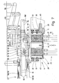
- the drying revolver 14 is set up for the simultaneous reception of two packs 10, 11 and is equipped for this purpose with two series of pockets 15, 16, each for receiving a pack 10, 11.
- the pockets 15, 16 are arranged in circular, concentric paths as pocket wreaths 17 and 18.
- the arrangement thereof or the relative position of the pockets 15, 16 is such that two pockets 15 and 16 of the pocket wreaths 7, 18 are arranged in radial alignment with one another.
- Shaped spacers 19, 20 of different sizes arranged so that the pockets 15 of the pocket ring 17 have a greater distance from one another than the pockets 16 of the pocket ring 18th
- the pockets 15, 16 are arranged and dimensioned such that the packs with the side walls 12, 13 are accommodated in the pockets 15, 16 in the radial direction pointing outwards or inwards.
- the dimensions of the pockets 15, 16 correspond to those of the packs 10, 11, so that their exact cuboid shape is produced or stabilized in the pockets 15, 16.
- the pockets 15, 16 are open on one side and closed on the back by a rear wall 21 - except for through openings 22, 23.
- the packs 10, 11 are introduced into the pockets 15, 16 in the axial direction via the open side opposite the rear wall 21 and pushed out in the opposite direction.
- the pockets 15, 16 are each assigned a double tappet 25, 26 in the region of an extension station 24.
- the two double plungers 25 and 26 are connected to one another and are actuated simultaneously.
- Tappets 27 pass through the openings 22, 23 of the rear wall 21 into the pockets 15, 16 and push the packs 10, 11 out over an end wall (top wall or bottom).
- the outer pockets 15 of the pocket ring 17 are equipped on the radially outer side and the inner pockets 16 of the inner pocket ring 18 on the radially inner side with a movable, elastically mounted pocket wall 28 or 29. This is accordingly on the respective outer or inner side wall 12 or 13 of the pack 10, namely under prestress due to compression springs 30, which are supported on the pocket walls 28, 29 on the one hand and an outer wall 31 or inner wall on the other. Tension pins surrounded by the compression springs 30 33 pass outwards through the outer wall 31 or through the inner wall 32.
- each holding heads 34 are attached, which are approximately T-shaped in cross section and which can be gripped by a tool, via the tie pins 33 connected to the pocket walls 28, 29, the pocket walls 28, 29 out of contact with the packs 10, 11 to move.
- the pocket walls 28, 29 are retracted radially outward or inward in the manner described, in order to enable the packs 10, 11 to be pushed in and pushed out.
- the pockets 15 and 16 are heated by an electrical resistance heater.
- the dry turret 14 is provided with two concentric slip rings 37, 38 adjacent to a turret hub 36. Fixed grinding electrodes 39, 40 (carbon electrodes) lie against these. These are supplied with electricity. Electrical lines 41, 42 lead from the slip rings 37, 38 to concentric heating tapes 43, 44 and 45. These are arranged in the region of the annular outer wall 31 as well as the inner wall 32 and an intermediate wall 46. The heating bands 43, 44 and 45 run around and thus heat all the pockets 15, 16.
- lift levers which are arranged in a fixed manner on the outside and inside of the drying revolver 14, namely outside lift levers 47 and 48 and inside lift levers 49 and 50, serve to lift the pocket walls 28 and 29 via the spring-loaded tension pins 33.
- 50 are provided with claws 51 at their ends.
- the holding heads 34 of the tension pins 33 move into these as a result of the rotary movement of the drying turret 14 in the extension station 24 and the insertion station 35.
- the claws 51 By designing the claws 51, the holding heads 34 are positively gripped in these stations.
- the claw 51 is designed to grip the two holding heads 34 per pocket wall 28, 29 with a corresponding width or as a double claw, as can be seen in FIG. 4.
- a special feature with regard to the actuation of the lift levers 47..50 is that the outer lift levers 47, 48 as well as the inner lift levers 49, 50 are each connected to one another in a geared manner.
- the outer lift lever 47 is designed in the present case as an angle lever and is connected to the second outer lift lever 48 via a pivot bearing 52. The latter is fixed in a pivot bearing 53.
- the free leg of the outer lift lever 47 is connected to a reciprocating crank arm 54. Its pivoting movements are thus transmitted to the outer lift lever 47 and from the same to the outer lift lever 48.
- the outer lift lever 47 is assigned to the insertion station 35 and the outer lift lever 48 to the extension station 24.
- the inner lift levers 49, 50 are designed in an analogous manner (FIG. 1).
- the inner lift lever 49 assigned to the extension station 24 is driven by a crank arm 55 which can be moved back and forth.
- the pivoting movements of the inner lift lever 49 are transmitted via a coupling 56 to the inner lift lever 50 assigned to the insertion station 35.
- the ejection station 24 is located in a radial plane below the (imaginary) horizontal center plane of the drying turret 14 rotating in an upright plane.
- the packs 10, 11 are transferred to a discharge conveyor 57, which consists of an upper and lower conveyor belt with a horizontal upper run 58 and lower run 59. Between the upper run 58 and lower run 59, the packs 10, 11 are spaced apart conveyed from each other, in an upright position, such that the side walls 12, 13 abut the upper run 58 and lower run 59.
- the packs 10, 11 are transferred to an intermediate conveyor 60 after exiting the drying turret 14, which transfers the packs 10, 11 individually to the discharge conveyor 57 along an arcuate conveyor path.
- the packs 10, 11 are brought from the flat lying position into the upright position during the transport in the intermediate conveyor 60.
- the intermediate conveyor 60 is designed as a continuously rotating conveyor wheel with elongated driver arms 62.
- the conveyor wheel 61 is designed in the manner of a spool of thread, as a result of which two driver arms 62 arranged at a distance from each other for gripping a pack 10, 11 in each area from the front or back wall.
- the intermediate conveyor 60 is fixed, namely in the region of the ejection station 24, next to the outer circumference of the drying turret 14, in such a way that the packs 10 ejected from the radially outer pockets 15 each reach a driving arm 62 of the conveyor wheel 61.
- the movements are coordinated with one another in such a way that the pack 10 is in a receiving position for the intermediate conveyor 60 when a driving arm 62 comes into this area from below as a result of the rotation of the feed wheel 61.
- the pack 10 in question is then conveyed approximately along a quarter circle and then enters the entry side of the discharge conveyor 57.
- the transfer of the packs 10, 11 from the conveyor wheel 61 to the discharge conveyor 57 is facilitated by the fact that this consists of two adjacent conveyor belts, that is to say also in the region of the upper run 58 and lower run 59.
- the intermediate conveyor 60 extends with a partial area between the conveyor belts. As a result, the packs can be conveyed into a position between upper run 58 and lower run 59 which is favorable for transport.
- a platform 63 is arranged in the region of the ejection station 24 in the ejection direction of the packs 10, 11 next to the drying turret 14. This extends as a tongue-like support member for the two packs 10, 11 into the region of the feed wheel 61. With an extension piece 64 of smaller width, the platform 63 projects between the two parts of the driving arms 62 of the feed wheel 61.
- the outer pack 10 is placed directly on this area of the platform 63 when it is ejected from the drying turret 10.
- the second pack 11 is then displaced on the platform 63 in the direction of the feed wheel 61, specifically by means of a slide member 65 which can be moved back and forth from the underside.
- This essentially consists of four connected by a U-frame 66 to form a unit upright drive pins 67, 68, which grip the pack 11 on the rear side wall 12 with respect to the conveying direction and on the lead opposite side wall 13 so that the pack 11 is moved exactly and positionally.
- the driver pins 67 and 68 are spaced from each other such that they extend to both sides of the platform 63 and can also be moved into a position on both sides of the conveyor wheel 61.
- the slide member 65 is arranged below the platform 63, is moved upward to take a pack 11 with it, and is then moved in a straight line (radial) therewith.
- the driver element 65 is lowered and returned to the starting position below the platform 63.
- the D-shaped movement curve 69 is shown in FIG. 6.
- crank arm 70 which is driven to swing back and forth in a plane parallel to the plane of the drying turret 14.
- the crank arm 70 contains two swing arms 71 and 72, which are articulated with the free ends on the slide member 65 and are attached with the other ends to a pivotably mounted coupling arm 73.
- the crank arm 70 is driven by a crank 74 (FIG. 5), which engages the swing arm 71.
- the platform 63 which extends in the area of the extension station 24 next to the drying turret 14, has a radially outward slope.
- further holding and guiding members are provided in order to place the packs 10, 11 on the platform 63 in an exact relative position and to feed them to the intermediate conveyor 60.
- the platform 63 which has a smaller width than the dimensions of the packs 8ö 10, 11, extends laterally - facing the drying turret 14 - an underpass 75 for the packs 11, 12 at a distance from the platform 63, so that the drivers pins 67, 68 between platform 63 and underpass 75 can be moved.
- the underpass 75 is provided in partial areas, namely in the area between the packs 10, 11 pushed out simultaneously, with an angularly adjoining side guide 76.
- the package 11, which is pushed out radially on the inside, is moved past this when it is fed to the intermediate conveyor 60.
- An upper guide 77 with an angular outline becomes effective in the area of the pack 11 during and after the ejection (s) from the dry turret 14.
- the upper guide 77 consists of a horizontal or in the plane of the top of the pack 11 itself Extending tongue 78 which is pivotally mounted laterally, namely on a pivot arm 79 which is mounted at a distance above the platform 63 and which carries further organs.
- An axis of rotation 80 of the upper guide 77 extends parallel to the conveying direction of the pack 11 on the platform 63.
- the upper guide 77 or its tongue 78 rests on the pack 11 under its own weight and thereby stabilizes its exact position on the platform 63.
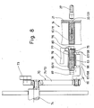
- a common pickup 81 is assigned to both packs. This consists of an angular pick-up arm 82, which is moved towards the packs 10, 11 at the start of the ejection movement (FIG. 8). The extension movement is then continued under contact with the pick-up arm 82, the pick-up arm 82 returning to the starting position (FIG. 7) with the same movement as the packs 10, 11.
- the pick-up arm 82 is attached to a parallelogram linkage 83 which is fixed in position with the free ends and is driven to swing back and forth by a push rod 84.
- an outer guide 85 is formed on the swivel arm 79 already mentioned. This is designed in the form of a circular arc and limits the outer movement path of the packs 10, 11 during transport by the conveyor wheel 61. As can be seen from FIG. 6, the outer guide 85 remains at a short distance from the packs 10, 11. Only come outward when there are displacements the packs 10, 11 during transport through the conveying wheel 61 to bear against the outer guide 85. As shown, this is designed as part or as an end region of the swivel arm 79. The swivel arm 79 in turn extends above the platform 63.
- a side guide piece 86 is attached to the swivel arm 79 or to the part forming the outer guide 85. This forms a lateral guide for the packs 10, 11 during transport through the conveyor wheel 61, specifically on the side facing the drying turret 14.
- the side guide piece 86 is a counterpart to the pick-up 81. The side guide piece 86 prevents the packs 10, 11 from being displaced on the driving arms 62 in the axial direction of the feed wheel 61.
- the outer guide 85 and the side guide piece 86 can be moved by the arrangement of the swivel arm 79.
- the pivot arm 79 is designed as a two-armed lever and can be pivoted about a lever bearing 87.
- a free end of the swivel arm 79 rests against a fixed stop 88, specifically as a result of the action of a tension spring 89.
- the swivel arm 79 is accordingly pulled against the stop 88 by the tension spring 89.
- the swivel arm 79 is pivoted clockwise against the load of the tension spring 89 (FIG. 5), so that the organs in question dodge and avoid breakage.
Landscapes
- Engineering & Computer Science (AREA)
- Mechanical Engineering (AREA)
- Wrapping Of Specific Fragile Articles (AREA)
Priority Applications (1)
| Application Number | Priority Date | Filing Date | Title |
|---|---|---|---|
| EP92117697A EP0529689B2 (fr) | 1987-10-28 | 1988-10-14 | Dispositif pour transférer des paquets parallelépipédiques |
Applications Claiming Priority (2)
| Application Number | Priority Date | Filing Date | Title |
|---|---|---|---|
| DE3736403 | 1987-10-28 | ||
| DE19873736403 DE3736403A1 (de) | 1987-10-28 | 1987-10-28 | Vorrichtung zum stabilisieren und trocknen von quaderfoermigen packungen |
Related Child Applications (2)
| Application Number | Title | Priority Date | Filing Date |
|---|---|---|---|
| EP92117697A Division EP0529689B2 (fr) | 1987-10-28 | 1988-10-14 | Dispositif pour transférer des paquets parallelépipédiques |
| EP92117697.0 Division-Into | 1992-10-16 |
Publications (2)
| Publication Number | Publication Date |
|---|---|
| EP0313938A1 true EP0313938A1 (fr) | 1989-05-03 |
| EP0313938B1 EP0313938B1 (fr) | 1993-09-29 |
Family
ID=6339208
Family Applications (2)
| Application Number | Title | Priority Date | Filing Date |
|---|---|---|---|
| EP92117697A Expired - Lifetime EP0529689B2 (fr) | 1987-10-28 | 1988-10-14 | Dispositif pour transférer des paquets parallelépipédiques |
| EP88117108A Expired - Lifetime EP0313938B1 (fr) | 1987-10-28 | 1988-10-14 | Dispositif de stabilisation et de séchage des paquets en forme de parallélépipède rectangle |
Family Applications Before (1)
| Application Number | Title | Priority Date | Filing Date |
|---|---|---|---|
| EP92117697A Expired - Lifetime EP0529689B2 (fr) | 1987-10-28 | 1988-10-14 | Dispositif pour transférer des paquets parallelépipédiques |
Country Status (6)
| Country | Link |
|---|---|
| US (1) | US4942715A (fr) |
| EP (2) | EP0529689B2 (fr) |
| JP (2) | JP2685248B2 (fr) |
| BR (1) | BR8805533A (fr) |
| CA (1) | CA1328637C (fr) |
| DE (3) | DE3736403A1 (fr) |
Cited By (2)
| Publication number | Priority date | Publication date | Assignee | Title |
|---|---|---|---|---|
| EP0529689A1 (fr) | 1987-10-28 | 1993-03-03 | Focke & Co. (GmbH & Co.) | Dispositif pour transférer des paquets parallelépipédiques |
| EP2093146A1 (fr) * | 2008-02-21 | 2009-08-26 | Focke & Co. (GmbH & Co. KG) | Procédé et dispositif de fabrication d'emballages pour cigarettes de type boîte en carton à couvercle rabattable |
Families Citing this family (17)
| Publication number | Priority date | Publication date | Assignee | Title |
|---|---|---|---|---|
| DE4037692C2 (de) * | 1990-11-27 | 1996-06-13 | Focke & Co | Vorrichtung zur Formgebung von Klappschachteln für Zigaretten |
| IT1252459B (it) * | 1991-07-29 | 1995-06-16 | Gd Spa | Unita' convogliatrice di uscita per macchine condizionatrici di sigarette in pacchetti rigidi a coperchio incernierato |
| DE4300149A1 (de) * | 1993-01-08 | 1994-07-14 | Focke & Co | Vorrichtung zum Herstellen von Zigaretten-Packungen |
| IT1306254B1 (it) * | 1995-05-05 | 2001-06-04 | Gd Spa | Metodo e macchina per l'impacchettamento di prodotti |
| DE19532092A1 (de) * | 1995-08-30 | 1997-03-06 | Focke & Co | Vorrichtung zum Fördern von Packungen |
| DE19641151A1 (de) * | 1996-10-07 | 1998-04-09 | Focke & Co | Weichbecher-Verpackung sowie Verfahren und Vorrichtung zum Herstellen derselben und anderer Verpackungen |
| DE19712937A1 (de) * | 1997-03-27 | 1998-10-01 | Topack Verpacktech Gmbh | Taschenrad zur Formfixierung von Klappdeckelpackungen der tabakverarbeitenden Industrie |
| GB9706984D0 (en) * | 1997-04-05 | 1997-05-21 | Molins Plc | Article handling apparatus |
| IT1299323B1 (it) * | 1998-01-27 | 2000-03-16 | Gd Spa | Macchina condizionatrice per pacchetti di sigarette. |
| WO2000044621A2 (fr) * | 1999-01-28 | 2000-08-03 | Molins Plc | Machine a empaqueter |
| DE10004022A1 (de) | 2000-01-31 | 2001-08-02 | Focke & Co | Verfahren und Vorrichtung zum Anbringen von Codierungen an (Zigaretten-)Packungen |
| ITFI20030012A1 (it) * | 2003-01-15 | 2004-07-16 | Giuseppe Piemontese | Un procedimento di sigillatura di capsule ed un'attrezzatura |
| DE102006059238A1 (de) * | 2006-12-13 | 2008-06-19 | Focke & Co.(Gmbh & Co. Kg) | Trockenrevolver für Zigarettenpackungen |
| DE102009050035A1 (de) * | 2009-10-20 | 2011-04-21 | Focke & Co.(Gmbh & Co. Kg) | Vorrichtung zum Speichern von (Zigaretten-)Packungen |
| DE102014012968A1 (de) * | 2014-09-08 | 2016-03-10 | Focke & Co. (Gmbh & Co. Kg) | Verfahren und Vorrichtung zur Formstabilisierung von Packungen |
| CN106347777B (zh) * | 2016-09-09 | 2018-12-21 | 湖北中烟工业有限责任公司 | 一种用于gdx包装机的熨烫装置 |
| CN110092025B (zh) * | 2019-05-31 | 2024-08-30 | 福建烟草机械有限公司 | 一种细支烟七号轮总成 |
Citations (6)
| Publication number | Priority date | Publication date | Assignee | Title |
|---|---|---|---|---|
| FR1123063A (fr) * | 1954-04-21 | 1956-09-17 | S I B Sa | Machine automatique multiple rotative pour empaqueter les cigarettes |
| US3590556A (en) * | 1968-01-05 | 1971-07-06 | Heinz Focke | Machine for packing of cigarettes in soft packets |
| US4179864A (en) * | 1976-07-22 | 1979-12-25 | Focke & Pfuhl | Apparatus for setting and shaping glued cigarette packs |
| DE3400650A1 (de) * | 1984-01-11 | 1985-07-18 | Focke & Co, 2810 Verden | Verpackungsmaschine fuer packungen mit durch klebung verbundenen faltlappen |
| EP0233470A2 (fr) * | 1986-02-19 | 1987-08-26 | Focke & Co. (GmbH & Co.) | Dispositif pour stocker des paquets (de cigarettes) |
| EP0275886A2 (fr) * | 1987-01-22 | 1988-07-27 | Focke & Co. (GmbH & Co.) | Machine d'emballage avec revolver de séchage |
Family Cites Families (11)
| Publication number | Priority date | Publication date | Assignee | Title |
|---|---|---|---|---|
| US2913864A (en) * | 1950-05-20 | 1959-11-24 | Redington Co F B | Package stacking and sealing mechanism |
| GB768525A (en) * | 1954-04-21 | 1957-02-20 | S I B S P A Scipione Innocenti | Improvements in or relating to rotary automatic cigarette packing machines |
| DE1586046B1 (de) * | 1967-01-07 | 1972-03-09 | Heinz Focke | Vorrichtung zum Verpacken von Zigaretten in Weichpackungen |
| IT1005326B (it) * | 1974-04-17 | 1976-08-20 | Gd Spa | Macchina per la formazione e l in carto di singoli pezzi come cara melle ed altri prodotti simili a partire da un cordone continuo di materiale plastico |
| DE2440006C2 (de) † | 1974-08-21 | 1984-06-28 | Focke & Co, 2810 Verden | Verfahren und Vorrichtung zum Herstellen von (quaderförmigen) Klappschachteln |
| DE2632968C2 (de) * | 1976-07-22 | 1985-04-18 | Focke & Pfuhl, 2810 Verden | Vorrichtung zur Formgebung bzw. Formverbesserung von quaderförmigen Packungen |
| JPS5918246A (ja) * | 1982-07-20 | 1984-01-30 | Japanese National Railways<Jnr> | デイ−ゼル機関の燃料噴射制御方法 |
| JPS6241922A (ja) * | 1985-08-20 | 1987-02-23 | Mazda Motor Corp | V型エンジンの吸気装置 |
| DE3613482C2 (de) * | 1986-04-22 | 1996-05-30 | Focke & Co | Vorrichtung zum formstabilisierenden Speichern von quaderförmigen Packungen |
| IT1192041B (it) * | 1986-05-27 | 1988-03-31 | Gd Spa | Dispositivo di uscita di una linea di impacchettamento |
| DE3736403A1 (de) † | 1987-10-28 | 1989-05-11 | Focke & Co | Vorrichtung zum stabilisieren und trocknen von quaderfoermigen packungen |
-
1987
- 1987-10-28 DE DE19873736403 patent/DE3736403A1/de not_active Withdrawn
-
1988
- 1988-10-05 CA CA000579337A patent/CA1328637C/fr not_active Expired - Fee Related
- 1988-10-14 EP EP92117697A patent/EP0529689B2/fr not_active Expired - Lifetime
- 1988-10-14 EP EP88117108A patent/EP0313938B1/fr not_active Expired - Lifetime
- 1988-10-14 DE DE3854439T patent/DE3854439D1/de not_active Expired - Fee Related
- 1988-10-14 DE DE88117108T patent/DE3884552D1/de not_active Expired - Fee Related
- 1988-10-18 JP JP63260690A patent/JP2685248B2/ja not_active Expired - Fee Related
- 1988-10-27 BR BR8805533A patent/BR8805533A/pt not_active IP Right Cessation
- 1988-10-27 US US07/263,574 patent/US4942715A/en not_active Expired - Lifetime
-
1997
- 1997-05-20 JP JP9129986A patent/JP2774095B2/ja not_active Expired - Fee Related
Patent Citations (6)
| Publication number | Priority date | Publication date | Assignee | Title |
|---|---|---|---|---|
| FR1123063A (fr) * | 1954-04-21 | 1956-09-17 | S I B Sa | Machine automatique multiple rotative pour empaqueter les cigarettes |
| US3590556A (en) * | 1968-01-05 | 1971-07-06 | Heinz Focke | Machine for packing of cigarettes in soft packets |
| US4179864A (en) * | 1976-07-22 | 1979-12-25 | Focke & Pfuhl | Apparatus for setting and shaping glued cigarette packs |
| DE3400650A1 (de) * | 1984-01-11 | 1985-07-18 | Focke & Co, 2810 Verden | Verpackungsmaschine fuer packungen mit durch klebung verbundenen faltlappen |
| EP0233470A2 (fr) * | 1986-02-19 | 1987-08-26 | Focke & Co. (GmbH & Co.) | Dispositif pour stocker des paquets (de cigarettes) |
| EP0275886A2 (fr) * | 1987-01-22 | 1988-07-27 | Focke & Co. (GmbH & Co.) | Machine d'emballage avec revolver de séchage |
Cited By (3)
| Publication number | Priority date | Publication date | Assignee | Title |
|---|---|---|---|---|
| EP0529689A1 (fr) | 1987-10-28 | 1993-03-03 | Focke & Co. (GmbH & Co.) | Dispositif pour transférer des paquets parallelépipédiques |
| EP0529689B2 (fr) † | 1987-10-28 | 1998-08-05 | Focke & Co. (GmbH & Co.) | Dispositif pour transférer des paquets parallelépipédiques |
| EP2093146A1 (fr) * | 2008-02-21 | 2009-08-26 | Focke & Co. (GmbH & Co. KG) | Procédé et dispositif de fabrication d'emballages pour cigarettes de type boîte en carton à couvercle rabattable |
Also Published As
| Publication number | Publication date |
|---|---|
| JP2685248B2 (ja) | 1997-12-03 |
| JP2774095B2 (ja) | 1998-07-09 |
| EP0529689B1 (fr) | 1995-09-06 |
| BR8805533A (pt) | 1989-07-04 |
| CA1328637C (fr) | 1994-04-19 |
| JPH1045108A (ja) | 1998-02-17 |
| EP0313938B1 (fr) | 1993-09-29 |
| DE3736403A1 (de) | 1989-05-11 |
| DE3854439D1 (de) | 1995-10-12 |
| EP0529689B2 (fr) | 1998-08-05 |
| US4942715A (en) | 1990-07-24 |
| JPH01139314A (ja) | 1989-05-31 |
| DE3884552D1 (de) | 1993-11-04 |
| EP0529689A1 (fr) | 1993-03-03 |
Similar Documents
| Publication | Publication Date | Title |
|---|---|---|
| EP0313938B1 (fr) | Dispositif de stabilisation et de séchage des paquets en forme de parallélépipède rectangle | |
| EP0258597B1 (fr) | Dispositif pour alimenter en ébauches une machine d'emballage | |
| EP2212204B1 (fr) | Dispositif pour remplir et fermer des sachets de tabac | |
| EP0034377B2 (fr) | Procédé et dispositif pour amener des objets, notamment des paquets, dans le trajet de circulation d'un convoyeur sans fin | |
| DE3046065C2 (de) | Bodenfaltungspacker | |
| EP0275481B2 (fr) | Procédé et dispositif pour emballer des mouchoirs en papier | |
| EP0275886B1 (fr) | Machine d'emballage avec revolver de séchage | |
| EP0113899B1 (fr) | Procédé et dispositif pour la fermeture de cartons | |
| DE2439565A1 (de) | Vorrichtung und verfahren zum automatischen beladen von kartons | |
| DE2254659C3 (de) | Bonboneinwickelmaschine | |
| DE3736868A1 (de) | Stapelvorrichtung an verpackungsmaschinen fuer beutel od. dgl. | |
| DE2407311A1 (de) | Verpackungsmaschine | |
| EP1448443A1 (fr) | Procede et dispositif de production d'emballages rigides pour des cigarettes | |
| DE3613482C2 (de) | Vorrichtung zum formstabilisierenden Speichern von quaderförmigen Packungen | |
| EP1125843B1 (fr) | Dispositif pour manipuler des flans, spécialement des banderoles d'emballages pour cigarettes | |
| DE2361545C2 (fr) | ||
| EP2490948B1 (fr) | Dispositif de stockage de paquets (de cigarettes) | |
| DE69411063T2 (de) | Verpackungsmaschine, insbesondere Maschine zum Verpacken von Zigaretten oder dergleichen | |
| EP0418687B1 (fr) | Machine d'emballage pour pliage des extrémités de l'enveloppe | |
| DE3441633C2 (de) | Verpackungsmaschine für quaderförmige Gegenstände | |
| EP2030896B1 (fr) | Procédé et dispositif de fabrication de paquets de cigarettes à couvercle articulé | |
| EP0233470B1 (fr) | Dispositif pour stocker des paquets (de cigarettes) | |
| DE2858074C2 (de) | Vorrichtung zur Übergabe von eingehüllten Zigarettengruppen an einen umlaufenden Revolver | |
| DE3815557A1 (de) | Verbundmaschine zum automatischen verpacken von packgut in faltschachteln | |
| DE1806663B2 (de) | Verpackungseinrichtung |
Legal Events
| Date | Code | Title | Description |
|---|---|---|---|
| PUAI | Public reference made under article 153(3) epc to a published international application that has entered the european phase |
Free format text: ORIGINAL CODE: 0009012 |
|
| AK | Designated contracting states |
Kind code of ref document: A1 Designated state(s): DE FR GB IT |
|
| 17P | Request for examination filed |
Effective date: 19891018 |
|
| 17Q | First examination report despatched |
Effective date: 19911119 |
|
| GRAA | (expected) grant |
Free format text: ORIGINAL CODE: 0009210 |
|
| AK | Designated contracting states |
Kind code of ref document: B1 Designated state(s): DE FR GB IT |
|
| XX | Miscellaneous (additional remarks) |
Free format text: TEILANMELDUNG 92117697.0 EINGEREICHT AM 14/10/88. |
|
| REF | Corresponds to: |
Ref document number: 3884552 Country of ref document: DE Date of ref document: 19931104 |
|
| GBT | Gb: translation of ep patent filed (gb section 77(6)(a)/1977) |
Effective date: 19931029 |
|
| ITF | It: translation for a ep patent filed | ||
| ET | Fr: translation filed | ||
| PLBE | No opposition filed within time limit |
Free format text: ORIGINAL CODE: 0009261 |
|
| STAA | Information on the status of an ep patent application or granted ep patent |
Free format text: STATUS: NO OPPOSITION FILED WITHIN TIME LIMIT |
|
| 26N | No opposition filed | ||
| PGFP | Annual fee paid to national office [announced via postgrant information from national office to epo] |
Ref country code: FR Payment date: 19991026 Year of fee payment: 12 |
|
| PG25 | Lapsed in a contracting state [announced via postgrant information from national office to epo] |
Ref country code: FR Free format text: LAPSE BECAUSE OF NON-PAYMENT OF DUE FEES Effective date: 20010629 |
|
| REG | Reference to a national code |
Ref country code: FR Ref legal event code: ST |
|
| REG | Reference to a national code |
Ref country code: GB Ref legal event code: IF02 |
|
| PGFP | Annual fee paid to national office [announced via postgrant information from national office to epo] |
Ref country code: GB Payment date: 20051012 Year of fee payment: 18 |
|
| PGFP | Annual fee paid to national office [announced via postgrant information from national office to epo] |
Ref country code: DE Payment date: 20051026 Year of fee payment: 18 |
|
| PGFP | Annual fee paid to national office [announced via postgrant information from national office to epo] |
Ref country code: IT Payment date: 20061031 Year of fee payment: 19 |
|
| PG25 | Lapsed in a contracting state [announced via postgrant information from national office to epo] |
Ref country code: DE Free format text: LAPSE BECAUSE OF NON-PAYMENT OF DUE FEES Effective date: 20070501 |
|
| GBPC | Gb: european patent ceased through non-payment of renewal fee |
Effective date: 20061014 |
|
| PG25 | Lapsed in a contracting state [announced via postgrant information from national office to epo] |
Ref country code: GB Free format text: LAPSE BECAUSE OF NON-PAYMENT OF DUE FEES Effective date: 20061014 |
|
| PG25 | Lapsed in a contracting state [announced via postgrant information from national office to epo] |
Ref country code: IT Free format text: LAPSE BECAUSE OF NON-PAYMENT OF DUE FEES Effective date: 20071014 |