EP0313958A2 - Spritz- oder Sprühpistole - Google Patents
Spritz- oder Sprühpistole Download PDFInfo
- Publication number
- EP0313958A2 EP0313958A2 EP88117291A EP88117291A EP0313958A2 EP 0313958 A2 EP0313958 A2 EP 0313958A2 EP 88117291 A EP88117291 A EP 88117291A EP 88117291 A EP88117291 A EP 88117291A EP 0313958 A2 EP0313958 A2 EP 0313958A2
- Authority
- EP
- European Patent Office
- Prior art keywords
- spray
- locking element
- handle
- spray gun
- gun according
- Prior art date
- Legal status (The legal status is an assumption and is not a legal conclusion. Google has not performed a legal analysis and makes no representation as to the accuracy of the status listed.)
- Granted
Links
Images

Classifications
-
- B—PERFORMING OPERATIONS; TRANSPORTING
- B05—SPRAYING OR ATOMISING IN GENERAL; APPLYING FLUENT MATERIALS TO SURFACES, IN GENERAL
- B05B—SPRAYING APPARATUS; ATOMISING APPARATUS; NOZZLES
- B05B15/00—Details of spraying plant or spraying apparatus not otherwise provided for; Accessories
-
- B—PERFORMING OPERATIONS; TRANSPORTING
- B05—SPRAYING OR ATOMISING IN GENERAL; APPLYING FLUENT MATERIALS TO SURFACES, IN GENERAL
- B05B—SPRAYING APPARATUS; ATOMISING APPARATUS; NOZZLES
- B05B12/00—Arrangements for controlling delivery; Arrangements for controlling the spray area
- B05B12/002—Manually-actuated controlling means, e.g. push buttons, levers or triggers
- B05B12/0022—Manually-actuated controlling means, e.g. push buttons, levers or triggers associated with means for restricting their movement
- B05B12/0024—Manually-actuated controlling means, e.g. push buttons, levers or triggers associated with means for restricting their movement to a single position
- B05B12/0026—Manually-actuated controlling means, e.g. push buttons, levers or triggers associated with means for restricting their movement to a single position to inhibit delivery
Definitions
- the invention relates to a spray gun with a handle, a trigger for pistol actuation and a locking element for the trigger.
- Such spray guns are widely known. They serve to apply powdery or liquid materials, such as paint or varnish, to an object to be coated.
- the pistol is actuated by moving the trigger lever with the index finger of the hand gripping the handle.
- the trigger must be secured against unintentional triggering. If such a locking element is present, the trigger must first go through an idle stroke before the actuated valve or the like can be actuated.
- the idle stroke takes into account the play in the area of the locking element and certain manufacturing and Material tolerances. If the idle stroke is too small, control can take place due to the instability of the components. If a sufficient idle stroke is selected, the actual working stroke can be shortened so much that the maximum amount of material is no longer ejected.
- the invention has for its object to provide a spray or spray gun of the type described above, in which the attachment of the locking device does not lead to an annoying shortening of the working stroke.
- the locking element is arranged at the lower end of a trigger lever rotatably mounted near its upper end and is displaceable from a release position outside the path of the lower end of the trigger lever into a locking position in this path.
- the idle stroke required at the actuation point of the valve or the like is reduced compared to the idle stroke in the area of the locking element to a value reduced in the ratio of the lever arms.
- the effective working stroke is only slightly reduced, so that it is always possible to achieve the maximum material output.
- the locking element is preferably loaded by a spring in the direction of the locking position. If no special measures are taken, the locking element returns to the locking position after the trigger is released.
- the trigger lever is gripped by a projection attached to the lower part of the handle and the locking element is accommodated in this projection. This is a particularly simple way to accommodate essential parts of the locking device so that they can engage at the lower end of the trigger.
- the projection can be designed as a removable handle insert. This makes assembly easier because the handle insert with its installation parts can be completed before the gun is assembled.
- the trigger lever carries at the lower end a rearward extension on which the locking element engages.
- the extension engages so far into the handle that it makes it easy to accommodate the locking element there.
- the locking element has an axially displaceable bolt.
- the bolt can engage directly or with an attached head in the movement path of the trigger.
- the surfaces guiding the bolt absorb the forces transmitted to the trigger lever in the locking position.
- the locking element is displaceable by an actuating element near the upper end of the handle. There the locking element can be easily reached by the other hand. There is also the option of actuation by the thumb of the hand gripping the handle, so that there is one-hand operation.
- the actuating element acts on an actuating rod axially displaceable in the handle on a pressure surface connected to the locking element. This results in a particularly simple construction.
- the locking element can be displaced by an actuating element near the lower end of the handle.
- This actuator can also be comfortably gripped by the other hand.
- the actuating element can, for example, be an axially movable button coupled to the locking element outside the handle. It is pulled out to release the trigger and remains in this position as long as the trigger is operated.
- the knob can also be rotatable and can be supported in at least one predetermined rotational angle position in an axial position corresponding to the release position of the locking element.
- the mode of operation just mentioned is then possible, but also a fixing of the locking element in the release position.
- the actuating element is a slide which can be moved transversely to the center plane of the pistol and which can be partially pushed out of the handle in both directions and has a control cam for engaging the locking element or a part coupled therewith. At the position Such an actuating element can be easily recognized whether the locking element is in the locking or in the release position. In addition, actuation with a finger of the hand holding the handle is also possible.
- control curve can be formed by two grooves of different depths which are connected to one another via two ramps of opposite inclination. Under the force of the spring acting on the locking element, the slide maintains its predetermined position.
- the actuating element is formed by the handle insert which can be displaced in the longitudinal direction of the gun against the force of a spring and which adjusts the locking element by means of a control cam.
- the trigger is released automatically when the handle is gripped by hand.
- control cam can be firmly connected to the displaceable handle insert and act on a cross pin connected to the locking element. This results in a simple structure.
- a rear gun body 1 has a handle 2, which can be gripped by one hand.
- a trigger 3 is rotatably held at its upper end in a bearing 4 on the rear gun part 1.
- a support plate 6 connected to an actuating rod 5 rests under the influence of a spring 7 near the bearing 4 on the trigger lever 3. With the actuating rod 5, for example, a material valve and / or an air valve can be actuated.
- the valve arrangement opens into its end position.
- a handle insert 8 is attached to the front of the lower part of the handle.
- a locking element 9 is guided in the form of a bolt, which is connected via a coupling rod 10 to a button-shaped actuating element 11 and is loaded by a spring 12.
- the locking element 9 engages in the path of movement at the bottom Provided end of the trigger, rearward extension 13, so that the trigger 3 can be moved at most by the small amount of angle that is required to insert the locking element 9 in the illustrated position.
- the actuating element 11 In order to be able to actuate the pistol, the actuating element 11 must be pulled into the dashed position. Then the trigger 3 can be pivoted into the working position shown in dashed lines, in which the actuated valve is fully open.
- the actuating element 111 is also rotatable. At its top, it is connected in one piece to a support element 14, which has a rectangular cross section, is supported in the illustrated position on the underside of the handle insert 108 and, after a rotation of 90 °, can engage in the transverse groove 15 under the force of the spring 12.
- the locking element 9 is therefore locked in the position of the actuating element 111 shown in FIG. 2 in the release position.
- the coupling rod 10 is connected to a pin 17 via a clamping device 16. This lies against the control curve 18 of a slide 19 which extends transversely to the center plane of the pistol and has a greater length than the width of the handle insert 208.
- the control curve 18 consists of two grooves 20 and 21 of different depths, which are connected to one another via two ramps 22 and 23 of different inclinations.
- the locking element 9 assumes the release position. If the pin 17 is in the groove 21, the locking element 9 assumes the locking position. In the release position, the right end 24 of the slide 19 protrudes laterally from the handle 208; in the locked position, the left end 25 of the slide 19 protrudes from the handle insert 208 on the opposite side. In both cases, pressure can be applied to the outer end of the slide in each case.
- the handle insert 308 can be moved against the force of a spring 26 from the fully extended position to the position shown in dashed lines.
- the handle insert has a guide element 27 which engages in a corresponding guide 28 of the handle 302.
- the coupling rod 10 is guided in the handle 302. It is firmly connected to a transverse pin 29 which engages in a control cam 30 formed in the handle insert 308.
- the locking element 9 is pulled down into the release position because of the shape of the control cam 30, so that the trigger lever 3 can be operated freely.
- all parts immediately return to the locked position.
- the locking element 409 is designed as the head of a bolt 410 which has a pressure surface 31 points.
- An actuating rod 32 acts on it, which can be axially adjusted by a slide 19, as illustrated in FIG. 4. This slide can be operated at least in one direction of actuation by the thumb of the hand holding the handle.
- the bottoms of the two grooves 20 and 21 of the slide 19 can be connected to one another by a ramp.
- the locking element would automatically return to the locking position when the trigger is released.
- the support device for the actuating element 111 in FIG. 2 can also be designed in such a way that run-up ramps are provided on the handle insert 106, onto which a narrow actuating element runs during the rotational movement.
Landscapes
- Nozzles (AREA)
- Coating By Spraying Or Casting (AREA)
- Particle Formation And Scattering Control In Inkjet Printers (AREA)
- Reciprocating Pumps (AREA)
- Containers And Packaging Bodies Having A Special Means To Remove Contents (AREA)
Abstract
Description
- Die Erfindung bezieht sich auf eine Spritz- oder Sprühpistole met einem Griffstück, einem Abzugshebel zur Pistolenbetätigung und einem Verriegelungselement für den Abzugshebel.
- Derartige Spritz- oder Sprühpistolen sind in weitem Umfang bekannt. Sie dienen dazu, pulverförmige Materialien oder flüssige Materialien, wie Farbe oder Lacke, auf einen zu beschichtenden Gegenstand aufzubringen. Durch Verlagerung des Abzugshebels mit Hilfe des Zeigefingers der das Griffstück umgreifenden Hand wird die Pistole betätigt. Je nach Aufbau der Pistole werden eine oder mehrere Materialventile, ein oder mehrere Luftventile, ein Schalter zur Hochspannungsversorgung einer elektrostatischen Zusatzeinrichtung u. dgl. betätigt. Aufgrund einer Richtlinie der Berufsgenossenschaft muß der Abzugshebel gegen unbeabsichtigtes Auslösen gesichert sein. Beim Vorhandensein eines solchen Verriegelungselements muß der Abzug zunächst einen Leerhub durchlaufen, ehe das angesteuerte Ventil o. dgl. betätigt werden darf. Der Leerhub berücksichtigt das Spiel im Bereich des Verriegelungselements und gewisse Fertigungs- und Materialtoleranzen. Ist der Leerhub zu klein, kann durch eine Labilität der Bauteile doch eine Ansteuerung erfolgen. Wird ein ausreichender Leerhub gewählt, kann der eigentliche Arbeitshub so stark verkürzt werden, daß nicht mehr die maximale Materialmenge ausgestoßen wird.
- Der Erfindung liegt die Aufgabe zugrunde, eine Spritz- oder Sprühpistole der eingangs beschriebenen Art anzugeben, bei der die Anbringung der Verriegelungsvorrichtung nicht zu einer störenden Verkürzung des Arbeitshubes führt.
- Diese Aufgabe wird erfindungsgemäß dadurch gelöst, daß das Verriegelungselement am unteren Ende eines nahe seinem oberen Ende drehbar gelagerten Abzugshebels angeordnet ist und aus einer Freigabestellung außerhalb der Bahn des unteren Endes des Abzugshebels in eine Verriegelungsstellung in dieser Bahn verlagerbar ist.
- Durch den Angriff des Verriegelungselements am freien Ende des Abzugshebels reduziert sich der an der Betätigungsstelle des Ventils o. dgl. erforderliche Leerhub gegenüber dem Leerhub im Bereich des Verriegelungselements auf einen im Verhältnis der Hebelarme verkleinerten Wert. Infolgedessen ist der wirksame Arbeitshub nur wenig verkleinert, so daß es immer möglich ist, den maximalen Materialausstoß zu erreichen.
- Vorzugsweise ist das Verriegelungselement durch eine Feder in Richtung der Verriegelungsstellung belastet. Wenn keine besonderen Maßnahmen getroffen sind, geht das Verriegelungselement jeweils nach Freigabe des Abzugshebels wieder in die Verriegelungsstellung zurück.
- Bei einer bevorzugten Ausführungsform ist der Abzugshebel durch einen am unteren Teil des Griffstücks angebrachten Vorsprung untergriffen und das Verriegelungselement ist in diesem Vorsprung untergebracht. Dies stellt eine besonders einfache Möglichkeit dar, wesentliche Teile der Verriegelungsvorrichtung so unterzubringen, daß sie am unteren Ende des Abzugshebels angreifen können.
- Insbesondere kann der Vorsprung als abnehmbarer Griffeinsatz ausgebildet sein. Dies erleichtert die Montage, weil der Griffeinsatz mit seinen Einbauteilen bereits vor dem Zusammenbau der Pistole fertiggestellt werden kann.
- Günstig ist es auch, daß der Abzugshebel am unteren Ende einen nach hinten gerichteten Fortsatz trägt, an dem das Verriegelungselement angreift. Der Fortsatz greift so weit in das Griffstück hinein, daß es keine Schwierigkeiten macht, dort das Verriegelungselement unterzubringen.
- Im einfachsten Fall weist das Verriegelungselement einen axial verschiebbaren Bolzen auf. Der Bolzen kann direkt oder mit einem angesetzten Kopf in die Bewegungsbahn des Abzugshebels greifen.
- Wenn sich der Bolzen etwa in Längsrichtung des Griffstücks erstreckt, nehmen die den Bolzen führenden Flächen die in der Verriegelungsstellung auf den Abzugshebel übertragenen Kräfte auf.
- Bei einer bevorzugten Ausführungsform ist das Verriegelungselement durch ein Betätigungselement nahe dem oberen Ende des Griffstücks verlagerbar. Dort kann das Verriegelungselement leicht durch die andere Hand erreicht werden. Darüber hinaus besteht die Möglichkeit der Betäti gung durch den Daumen der das Griffstück umgreifenden Hand, so daß sich eine Ein-Hand-Bedienung ergibt.
- In diesem Fall empfiehlt es sich, daß das Betätigungselement über eine im Griffstück axial verlagerbare Betätigungsstange auf eine mit dem Verriegelungselement verbundene Druckfläche wirkt. Dies ergibt eine besonders einfache Konstruktion.
- Bei einer Alternative ist das Verriegelungselement durch ein Betätigungselement nahe dem unteren Ende des Griffstücks verlagerbar. Auch diese Betätigungselement kann bequem durch die andere Hand ergriffen werden. Darüber hinaus besteht die Möglichkeit der Betätigung durch den kleinen Finger der das Griffstück umfassenden Hand, so daß sich wiederum eine Ein-Hand-Bedienung ergibt.
- Das Betätigungselement kann beispielsweise ein mit dem Verriegelungselement gekuppelter, axial bewegbarer Knopf außerhalb des Griffstücks sein. Er wird zur Freigabe des Abzugshebels herausgezogen und bleibt in dieser Stellung, solange der Abzugshebel betätigt ist.
- Der Knopf kann aber auch drehbar und in mindestens einer vorgegebenen Drehwinkellage in einer der Freigabestellung des Verriegelungselements entsprechenden Axiallage abstützbar sein. Es ist dann die soeben erwähnte Betriebsweise möglich, aber auch eine Festlegung des Verriegelungselements in der Freigabestellung.
- Besonders gute Ergebnisse erzielt man dadurch, daß das Betätigungselement ein quer zur Pistolenmittelebene bewegbarer Schieber ist, der in beiden Richtungen teilweise aus dem Griffstück herausschiebbar ist und eine Steuerkurve zur Anlage des Verriegelungselements oder eines damit gekuppelten Teiles aufweist. An der Stellung eines solchen Betätigungselements läßt sich leicht erkennen, ob das Verriegelungselement in der Verriegelungs- oder in der Freigabestellung steht. Außerdem ist auch eine Betätigung mit einem Finger der den Griff haltenden Hand möglich.
- Insbesondere kann die Steuerkurve durch zwei unterschiedlich tiefe Nuten gebildet sein, die über zwei Rampen entgegengesetzter Neigung miteinander verbunden sind. Unter der Kraft der auf das Verriegelungselement wirkenden Feder behält der Schieber seine jeweils vorgegebene Position bei.
- Eine andere Möglichkeit besteht darin, daß das Betätigungselement durch den Griffeinsatz gebildet ist, der in Längsrichtung der Pistole gegen die Kraft einer Feder verlagerbar ist und mittels einer Steuerkurve das Verriegelungselement verstellt. Hier erfolgt eine automatische Freigabe des Abzugshebels, wenn das Griffstück mit der Hand erfaßt wird.
- Insbesondere kann hierbei Steuerkurve mit dem verlagerbaren Griffeinsatz fest verbunden sein und auf einen mit dem Verriegelungselement verbundenen Querstift wirken. Dies ergibt einen einfachen Aufbau.
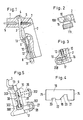
- Die Erfindung wird nachstehend anhand in der Zeichnung dargestellter, bevorzugter Ausführungsbeispiele näher erläutert. Es zeigen:
- Fig. 1 eine Seitenansicht, teilweise im Schnitt, des hinteren Teils einer Spritz- oder Sprühpistole,
- Fig. 2 in Seitenansicht, teilweise im Schnitt, den unteren Teil des Griffstücks einer abgewandelten Ausführungsform,
- Fig. 3 im Schnitt den unteren Teil eines Griffstücks einer weiteren Ausführungsform,
- Fig. 4 die Vorderansicht eines in Fig. 3 verwendeten Schiebers,
- Fig. 5 die schematische Darstellung eines verstellbaren Griffeinsatzes in Verbindung mit dem Verriegelungselement und
- Fig. 6 eine Seitenansicht, teilweise im Schnitt, eines hinteren Teils einer Spritz- oder Sprühpistole in einer weiteren Ausführungsform.
- In Fig. 1 besitzt ein hinterer Pistolenkörper 1 ein Griffstück 2, das von einer Hand umfaßt werden kann. Ein Abzugshebel 3 ist an seinem oberen Ende in einem Lager 4 drehbar am hinteren Pistolenteil 1 gehalten. Ein mit einer Betätigungsstange 5 verbundener Stützteller 6 liegt unter dem Einfluß einer Feder 7 nahe dem Lager 4 am Abzugshebel 3 an. Mit der Betätigungsstange 5 kann beispielsweise ein Materialventil und/oder ein Luftventil betätigt werden. Wenn der Abzugshebel 3 aus seiner vollausgezogenen Stellung in die gestrichelt gezeichnete Stellung verschwenkt wird, öffnet sich die Ventilanordnung bis in ihre Endstellung.
- Am unteren Teil des Griffstücks ist vorn ein Griffeinsatz 8 angebracht. In diesem ist ein Verriegelungselement 9 in der Form eines Bolzens geführt, das über eine Kupplungsstange 10 mit einem knopfförmigen Betätigungselement 11 verbunden und durch eine Feder 12 belastet ist.
- In der veranschaulichten Stellung greift das Verriegelungselement 9 in die Bewegungsbahn eines am unteren Ende des Abzugshebels vorgesehen, nach hinten gerichteten Fortsatzes 13, so daß der Abzugshebel 3 höchstens um den kleinen Winkelbetrag bewegt werden kann, der zum Einschieben des Verriegelungselements 9 in die veranschaulichte Stellung erforderlich ist. Um die Pistole betätigen zu können, muß das Betätigungselement 11 in die gestrichelte Stellung gezogen werden. Dann kann der Abzugshebel 3 in die gestrichelt gezeichnete Arbeitsstellung verschwenkt werden, in der das betätigte Ventil voll geöffnet ist.
- Bei der Abwandlung nach Fig. 2 werden für identische Teile dieselben und für entsprechende Teile um 100 erhöhte Bezugszeichen verwendet. Hier ist das Betätigungselement 111 auch drehbar. An seiner Oberseite ist es einstückig mit einem Stützelement 14 verbunden, das rechteckigen Querschnitt hat, sich in der veranschaulichten Stellung auf der Unterseite des Griffeinsatzes 108 abstützt und nach einer Drehung um 90° unter der Kraft der Feder 12 in die Quernut 15 eingreifen kann. Das Verriegelungselement 9 ist daher in der in Fig. 2 dargestellten Lage des Betätigungselementes 111 in der Freigabestellung arretiert.
- Bei der Ausführungsform der Fig. 3 und 4, in der für entsprechende Teile um 200 erhöhte Bezugszeichen verwendet werden, ist die Kupplungsstange 10 über eine Klemmvorrichtung 16 mit einem Stift 17 verbunden. Dieser liegt an der Steuerkurve 18 eines Schiebers 19 an, welcher sich quer zur Pistolenmittelebene erstreckt und eine größere Länge als die Breite des Griffeinsatzes 208 hat. Die Steuerkurve 18 besteht aus zwei unterschiedlich tiefen Nuten 20 und 21, die über zwei Rampen 22 und 23 unterschiedlicher Neigung miteinander verbunden sind.
- Wenn sich der Stift 17 in der Nut 20 befindet, nimmt das Verriegelungselement 9 die Freigabestellung ein. Befindet sich der Stift 17 in der Nut 21, nimmt das Verriegelungselement 9 die Verriegelungsstellung ein. In der Freigabestellung ragt das rechte Ende 24 des Schiebers 19 seitlich aus dem Griffstück 208; in der Verriegelungsstellung ragt das linke Ende 25 des Schiebers 19 auf der gegenüberliegenden Seite aus dem Griffeinsatz 208. In beiden Fällen kann durch einen Druck auf das jeweils außen befindliche Ende des Schiebers ein Umschalten erfolgen.
- Bei der Ausführungsform nach Fig. 5, bei der für entsprechende Teile um 300 erhöhte Bezugszeichen verwendet werden, sind nur bruchstückhafte Teile des Griffstücks 302 dargestellt. Der Griffeinsatz 308 ist gegen die Kraft einer Feder 26 aus der vollausgezogenen Stellung in die gestrichelt gezeichnete Stellung verlagerbar. Hierbei besitzt der Griffeinsatz ein Führungselement 27, das in eine entsprechende Führung 28 des Griffstücks 302 eingreift. Die Kupplungsstange 10 ist im Griffstück 302 geführt. Sie ist mit einem Querstift 29 fest verbunden, der in eine im Griffeinsatz 308 ausgebildeten Steuerkurve 30 greift. Wird die Pistole aufgenommen, drücken die dritten bis fünften Finger der Hand den Griffeinsatz 308 nach hinten. Hierdurch wird das Verriegelungselement 9 wegen der Form der Steuerkurve 30 nach unten in die Freigabestellung gezogen, so daß der Abzugshebel 3 frei betätigt werden kann. Beim Loslassen des Griffstücks kehren alle Teile sofort in die Verriegelungsstellung zurück.
- Bei der Ausführungsform nach Fig. 6, bei der für entsprechende Teile um 400 erhöhte Bezugszeichen verwendet werden, ist das Verriegelungselement 409 als Kopf eines Bolzens 410 ausgebildet, der eine Druckfläche 31 auf weist. Auf sie wirkt eine Betätigungsstange 32, die durch einen Schieber 19, wie er in Fig. 4 veranschaulicht ist, axial verstellt werden kann. Dieser Schieber kann zumindest in der einen Betätigungsrichtung durch den Daumen der das Griffstück haltenden Hand betätigt werden.
- Von den dargestellten Ausführungsformen kann in vielerlei Hinsicht abgewichen werden, ohne den Grundgedanken der Neuerung zu verlassen. Beispielsweise können die Böden der beiden Nuten 20 und 21 des Schiebers 19 durch eine Rampe miteinander verbunden werden. In diesem Fall würde das Verriegelungselement selbsttätig in die Verriegelungsstellung zurückkehren, wenn der Abzugshebel freigegeben wird. Die Stützvorrichtung für das Betätigungselement 111 in Fig. 2 kann auch so ausgeführt werden, daß auf dem Griffeinsatz 106 Auflauframpen vorgesehen sind, auf die ein schmales Betätigungselement bei der Drehbewegung aufläuft.
Claims (16)
Priority Applications (1)
| Application Number | Priority Date | Filing Date | Title |
|---|---|---|---|
| AT88117291T ATE70470T1 (de) | 1987-10-27 | 1988-10-18 | Spritz- oder spruehpistole. |
Applications Claiming Priority (2)
| Application Number | Priority Date | Filing Date | Title |
|---|---|---|---|
| DE8714271U | 1987-10-27 | ||
| DE8714271U DE8714271U1 (de) | 1987-10-27 | 1987-10-27 | Spritz- oder Sprühpistole |
Publications (3)
| Publication Number | Publication Date |
|---|---|
| EP0313958A2 true EP0313958A2 (de) | 1989-05-03 |
| EP0313958A3 EP0313958A3 (en) | 1990-01-17 |
| EP0313958B1 EP0313958B1 (de) | 1991-12-18 |
Family
ID=6813431
Family Applications (1)
| Application Number | Title | Priority Date | Filing Date |
|---|---|---|---|
| EP88117291A Expired - Lifetime EP0313958B1 (de) | 1987-10-27 | 1988-10-18 | Spritz- oder Sprühpistole |
Country Status (3)
| Country | Link |
|---|---|
| EP (1) | EP0313958B1 (de) |
| AT (1) | ATE70470T1 (de) |
| DE (2) | DE8714271U1 (de) |
Cited By (14)
| Publication number | Priority date | Publication date | Assignee | Title |
|---|---|---|---|---|
| EP0715827A3 (de) * | 1994-12-08 | 1996-10-02 | Kaercher Gmbh & Co Alfred | Handstück für ein Dampfreinigungsgerät |
| USD835235S1 (en) | 2014-07-31 | 2018-12-04 | Sata Gmbh & Co. Kg | Paint spray gun |
| US10189037B2 (en) | 2011-06-30 | 2019-01-29 | Sata Gmbh & Co. Kg | Easy-to-clean spray gun, accessories therefor, and mounting and dismounting methods |
| US10464076B2 (en) | 2015-12-21 | 2019-11-05 | Sata Gmbh & Co. Kg | Air cap and nozzle assembly for a spray gun, and spray gun |
| US10471449B2 (en) | 2016-08-19 | 2019-11-12 | Sata Gmbh & Co. Kg | Air cap arrangement and spray gun |
| US10702879B2 (en) | 2014-07-31 | 2020-07-07 | Sata Gmbh & Co. Kg | Spray gun manufacturing method, spray gun, spray gun body and cover |
| US10835911B2 (en) | 2016-08-19 | 2020-11-17 | Sata Gmbh & Co. Kg | Trigger for a spray gun and spray gun having same |
| US11141747B2 (en) | 2015-05-22 | 2021-10-12 | Sata Gmbh & Co. Kg | Nozzle arrangement for a spray gun |
| US11801521B2 (en) | 2018-08-01 | 2023-10-31 | Sata Gmbh & Co. Kg | Main body for a spray gun, spray guns, spray gun set, method for producing a main body for a spray gun and method for converting a spray gun |
| US11826771B2 (en) | 2018-08-01 | 2023-11-28 | Sata Gmbh & Co. Kg | Set of nozzles for a spray gun, spray gun system, method for embodying a nozzle module, method for selecting a nozzle module from a set of nozzles for a paint job, selection system and computer program product |
| US11865558B2 (en) | 2018-08-01 | 2024-01-09 | Sata Gmbh & Co. Kg | Nozzle for a spray gun, nozzle set for a spray gun, spray guns and methods for producing a nozzle for a spray gun |
| US12097519B2 (en) | 2020-09-11 | 2024-09-24 | Sata Gmbh & Co. Kg | Sealing element for sealing a transition between a spray gun body and an attachment of a spray gun, attachment, in particular a paint nozzle arrangement for a spray gun and a spray gun, in particular a paint spray gun |
| US12515230B2 (en) | 2018-09-10 | 2026-01-06 | Sata Gmbh & Co. Kg | Paint gun, material application system, and method for operating same |
| US12594566B2 (en) | 2020-03-06 | 2026-04-07 | Sata Gmbh & Co. Kg | Spray gun, in particular a pressurized air atomization paint spray gun, in particular a hand-held pressurized air atomization paint spray gun |
Families Citing this family (7)
| Publication number | Priority date | Publication date | Assignee | Title |
|---|---|---|---|---|
| US5069391A (en) * | 1990-03-22 | 1991-12-03 | Shop Vac Corporation | Dual-activator safety switch for liquid sprayer |
| DE9320260U1 (de) * | 1993-12-09 | 1995-04-06 | OSU-Maschinenbau GmbH, 44577 Castrop-Rauxel | Spritzpistole mit Totmannschaltung |
| DE102013212672A1 (de) * | 2013-06-28 | 2014-12-31 | Robert Bosch Gmbh | Elektrowerkzeugmaschinenschaltvorrichtung |
| CN104475285A (zh) * | 2014-12-02 | 2015-04-01 | 国网青海省电力公司海东供电公司 | 一种输电线路色标喷刷器 |
| DE202016005029U1 (de) | 2016-08-19 | 2016-10-06 | Sata Gmbh & Co. Kg | Spritzpistole mit Abzugssperre und Abzugssperre für eine Spritzpistole |
| DE102016009957A1 (de) | 2016-08-19 | 2018-02-22 | Sata Gmbh & Co. Kg | Spritzpistole mit Abzugssperre, Abzugssperre für eine Spritzpistole und Verfahren zum Anbringen, zum Aktivieren und zum Deaktivieren einer Abzugssperre |
| DE102019126493A1 (de) * | 2019-10-01 | 2021-04-01 | Steinel Gmbh | Elektrisches, pistolenartiges Handgerät |
Family Cites Families (5)
| Publication number | Priority date | Publication date | Assignee | Title |
|---|---|---|---|---|
| US3633828A (en) * | 1970-01-19 | 1972-01-11 | Graco Inc | Spray gun |
| DE2345504C3 (de) * | 1973-09-08 | 1981-12-03 | Kränzle, Josef, 7918 Illertissen | Halte- und Betätigungsvorrichtung für Spritzeinrichtungen für Waschanlagen |
| US4166579A (en) * | 1976-09-07 | 1979-09-04 | Stewart-Warner Corporation | Paint sprayer safety interlock |
| US4225087A (en) * | 1977-02-22 | 1980-09-30 | The Sherwin-Williams Company | Lock-off means for airless sprayer |
| DE3407744C2 (de) * | 1984-03-02 | 1986-01-23 | Alfred Kärcher GmbH & Co, 7057 Winnenden | Handspritzpistole für ein Hochdruckreinigungsgerät |
-
1987
- 1987-10-27 DE DE8714271U patent/DE8714271U1/de not_active Expired
-
1988
- 1988-10-18 EP EP88117291A patent/EP0313958B1/de not_active Expired - Lifetime
- 1988-10-18 AT AT88117291T patent/ATE70470T1/de not_active IP Right Cessation
- 1988-10-18 DE DE8888117291T patent/DE3867031D1/de not_active Expired - Fee Related
Cited By (14)
| Publication number | Priority date | Publication date | Assignee | Title |
|---|---|---|---|---|
| EP0715827A3 (de) * | 1994-12-08 | 1996-10-02 | Kaercher Gmbh & Co Alfred | Handstück für ein Dampfreinigungsgerät |
| US10189037B2 (en) | 2011-06-30 | 2019-01-29 | Sata Gmbh & Co. Kg | Easy-to-clean spray gun, accessories therefor, and mounting and dismounting methods |
| USD835235S1 (en) | 2014-07-31 | 2018-12-04 | Sata Gmbh & Co. Kg | Paint spray gun |
| US10702879B2 (en) | 2014-07-31 | 2020-07-07 | Sata Gmbh & Co. Kg | Spray gun manufacturing method, spray gun, spray gun body and cover |
| US11141747B2 (en) | 2015-05-22 | 2021-10-12 | Sata Gmbh & Co. Kg | Nozzle arrangement for a spray gun |
| US10464076B2 (en) | 2015-12-21 | 2019-11-05 | Sata Gmbh & Co. Kg | Air cap and nozzle assembly for a spray gun, and spray gun |
| US10835911B2 (en) | 2016-08-19 | 2020-11-17 | Sata Gmbh & Co. Kg | Trigger for a spray gun and spray gun having same |
| US10471449B2 (en) | 2016-08-19 | 2019-11-12 | Sata Gmbh & Co. Kg | Air cap arrangement and spray gun |
| US11801521B2 (en) | 2018-08-01 | 2023-10-31 | Sata Gmbh & Co. Kg | Main body for a spray gun, spray guns, spray gun set, method for producing a main body for a spray gun and method for converting a spray gun |
| US11826771B2 (en) | 2018-08-01 | 2023-11-28 | Sata Gmbh & Co. Kg | Set of nozzles for a spray gun, spray gun system, method for embodying a nozzle module, method for selecting a nozzle module from a set of nozzles for a paint job, selection system and computer program product |
| US11865558B2 (en) | 2018-08-01 | 2024-01-09 | Sata Gmbh & Co. Kg | Nozzle for a spray gun, nozzle set for a spray gun, spray guns and methods for producing a nozzle for a spray gun |
| US12515230B2 (en) | 2018-09-10 | 2026-01-06 | Sata Gmbh & Co. Kg | Paint gun, material application system, and method for operating same |
| US12594566B2 (en) | 2020-03-06 | 2026-04-07 | Sata Gmbh & Co. Kg | Spray gun, in particular a pressurized air atomization paint spray gun, in particular a hand-held pressurized air atomization paint spray gun |
| US12097519B2 (en) | 2020-09-11 | 2024-09-24 | Sata Gmbh & Co. Kg | Sealing element for sealing a transition between a spray gun body and an attachment of a spray gun, attachment, in particular a paint nozzle arrangement for a spray gun and a spray gun, in particular a paint spray gun |
Also Published As
| Publication number | Publication date |
|---|---|
| DE8714271U1 (de) | 1987-12-17 |
| EP0313958B1 (de) | 1991-12-18 |
| ATE70470T1 (de) | 1992-01-15 |
| DE3867031D1 (de) | 1992-01-30 |
| EP0313958A3 (en) | 1990-01-17 |
Similar Documents
| Publication | Publication Date | Title |
|---|---|---|
| EP0313958B1 (de) | Spritz- oder Sprühpistole | |
| DE1563788C3 (de) | Handbetätigtes Stellglied zur stufenlosen Drehzahlsteuerung eines Elektrowerkzeuges | |
| DE2315841C3 (de) | Im Handgriff einer elektromotorisch angetriebenen Handwerkzeugmaschine angeordnete Betätigungsvorrichtung | |
| DE2335972C3 (de) | Schalter, insbesondere für ein elektrisches Handwerkzeug | |
| DE69312151T2 (de) | Pipettiervorrichtung mit einem Abwerfer für Pipettenspitzen | |
| DE2915041C2 (de) | Spritzpistole | |
| DE2935552A1 (de) | Markierungsgeraet | |
| DE3204178A1 (de) | Pipettiervorrichtung | |
| DE2549477A1 (de) | Pipettiervorrichtung | |
| DE19508437A1 (de) | Einstellvorrichtung zum Einstellen der Tiefe, bis zu der ein Nagelgerät Nägel in ein Werkstück eintreibt | |
| DE1552426B2 (de) | Schaltvorrichtung im griff eines tragbaren arbeitsgeraetes | |
| DE2603784A1 (de) | Sicherheitslufteinlass-ventilsteuerung fuer ein druckluftbetriebenes handwerkzeug | |
| EP3858486A1 (de) | Pipette und verfahren zum einstellen eines zu pipettierenden volumens einer pipette | |
| DE3120486C2 (de) | ||
| DE2811339B1 (de) | Ausloesesicherung an einem Druckluftnagler | |
| DE10038013B4 (de) | Steuergerät für eine Vakuum-Hebevorrichtung | |
| DE2450577A1 (de) | Schalter fuer elektro-handwerkzeuge | |
| DE3100703C2 (de) | Sicherheitsvorrichtung für einen pneumatisch oder elektrisch betriebenen Nagler | |
| DE102006050430A1 (de) | Handgeführtes Arbeitsgerät | |
| DE3147886A1 (de) | Elektrische abzugsvorrichtung fuer schusswaffen | |
| DE102012109701B4 (de) | Magazin für ein Repetiergewehr und Repetiergewehr mit einem derartigen Magazin | |
| DE3543374A1 (de) | Tacker mit kraftantrieb und einer freischusssicherung | |
| DE3604147A1 (de) | Spritzpistole | |
| DE3518492A1 (de) | Spritzpistole | |
| DE10321993B4 (de) | Handfeuerwaffe mit beidseitig betätigbarer Magazinhalterung |
Legal Events
| Date | Code | Title | Description |
|---|---|---|---|
| PUAI | Public reference made under article 153(3) epc to a published international application that has entered the european phase |
Free format text: ORIGINAL CODE: 0009012 |
|
| AK | Designated contracting states |
Kind code of ref document: A2 Designated state(s): AT BE DE FR GB IT NL SE |
|
| PUAL | Search report despatched |
Free format text: ORIGINAL CODE: 0009013 |
|
| AK | Designated contracting states |
Kind code of ref document: A3 Designated state(s): AT BE DE FR GB IT NL SE |
|
| 17P | Request for examination filed |
Effective date: 19900305 |
|
| RAP1 | Party data changed (applicant data changed or rights of an application transferred) |
Owner name: BOELLHOFF VERFAHRENSTECHNIK GMBH & CO. KG |
|
| 17Q | First examination report despatched |
Effective date: 19901206 |
|
| GRAA | (expected) grant |
Free format text: ORIGINAL CODE: 0009210 |
|
| AK | Designated contracting states |
Kind code of ref document: B1 Designated state(s): AT BE DE FR GB IT NL SE |
|
| REF | Corresponds to: |
Ref document number: 70470 Country of ref document: AT Date of ref document: 19920115 Kind code of ref document: T |
|
| ITF | It: translation for a ep patent filed | ||
| REF | Corresponds to: |
Ref document number: 3867031 Country of ref document: DE Date of ref document: 19920130 |
|
| ET | Fr: translation filed | ||
| GBT | Gb: translation of ep patent filed (gb section 77(6)(a)/1977) | ||
| PLBE | No opposition filed within time limit |
Free format text: ORIGINAL CODE: 0009261 |
|
| STAA | Information on the status of an ep patent application or granted ep patent |
Free format text: STATUS: NO OPPOSITION FILED WITHIN TIME LIMIT |
|
| 26N | No opposition filed | ||
| PGFP | Annual fee paid to national office [announced via postgrant information from national office to epo] |
Ref country code: SE Payment date: 19931011 Year of fee payment: 6 |
|
| PGFP | Annual fee paid to national office [announced via postgrant information from national office to epo] |
Ref country code: GB Payment date: 19931013 Year of fee payment: 6 |
|
| PGFP | Annual fee paid to national office [announced via postgrant information from national office to epo] |
Ref country code: BE Payment date: 19931020 Year of fee payment: 6 |
|
| PGFP | Annual fee paid to national office [announced via postgrant information from national office to epo] |
Ref country code: FR Payment date: 19931021 Year of fee payment: 6 |
|
| PGFP | Annual fee paid to national office [announced via postgrant information from national office to epo] |
Ref country code: AT Payment date: 19931029 Year of fee payment: 6 |
|
| PGFP | Annual fee paid to national office [announced via postgrant information from national office to epo] |
Ref country code: NL Payment date: 19931031 Year of fee payment: 6 |
|
| PG25 | Lapsed in a contracting state [announced via postgrant information from national office to epo] |
Ref country code: GB Effective date: 19941018 Ref country code: AT Effective date: 19941018 |
|
| PG25 | Lapsed in a contracting state [announced via postgrant information from national office to epo] |
Ref country code: SE Effective date: 19941019 |
|
| PG25 | Lapsed in a contracting state [announced via postgrant information from national office to epo] |
Ref country code: BE Effective date: 19941031 |
|
| EAL | Se: european patent in force in sweden |
Ref document number: 88117291.0 |
|
| BERE | Be: lapsed |
Owner name: BOLLHOFF VERFAHRENSTECHNIK G.M.B.H. & CO. K.G. Effective date: 19941031 |
|
| PG25 | Lapsed in a contracting state [announced via postgrant information from national office to epo] |
Ref country code: NL Effective date: 19950501 |
|
| GBPC | Gb: european patent ceased through non-payment of renewal fee |
Effective date: 19941018 |
|
| NLV4 | Nl: lapsed or anulled due to non-payment of the annual fee | ||
| PG25 | Lapsed in a contracting state [announced via postgrant information from national office to epo] |
Ref country code: FR Effective date: 19950630 |
|
| EUG | Se: european patent has lapsed |
Ref document number: 88117291.0 |
|
| REG | Reference to a national code |
Ref country code: FR Ref legal event code: ST |
|
| PGFP | Annual fee paid to national office [announced via postgrant information from national office to epo] |
Ref country code: DE Payment date: 19951019 Year of fee payment: 8 |
|
| PG25 | Lapsed in a contracting state [announced via postgrant information from national office to epo] |
Ref country code: DE Effective date: 19970701 |
|
| PG25 | Lapsed in a contracting state [announced via postgrant information from national office to epo] |
Ref country code: IT Free format text: LAPSE BECAUSE OF NON-PAYMENT OF DUE FEES Effective date: 20051018 |