EP0314103A2 - Procédé et dispositif pour l'entraînement sans contact d'un interféromètre à pendule double - Google Patents
Procédé et dispositif pour l'entraînement sans contact d'un interféromètre à pendule double Download PDFInfo
- Publication number
- EP0314103A2 EP0314103A2 EP88117841A EP88117841A EP0314103A2 EP 0314103 A2 EP0314103 A2 EP 0314103A2 EP 88117841 A EP88117841 A EP 88117841A EP 88117841 A EP88117841 A EP 88117841A EP 0314103 A2 EP0314103 A2 EP 0314103A2
- Authority
- EP
- European Patent Office
- Prior art keywords
- double pendulum
- interferometer
- laser
- pendulum
- electromagnetic system
- Prior art date
- Legal status (The legal status is an assumption and is not a legal conclusion. Google has not performed a legal analysis and makes no representation as to the accuracy of the status listed.)
- Withdrawn
Links
- 238000000034 method Methods 0.000 title claims description 14
- 230000003287 optical effect Effects 0.000 claims abstract description 56
- 230000005855 radiation Effects 0.000 claims abstract description 24
- 230000033001 locomotion Effects 0.000 claims abstract description 21
- 230000001133 acceleration Effects 0.000 claims description 5
- 230000002123 temporal effect Effects 0.000 claims description 5
- 230000010355 oscillation Effects 0.000 claims description 4
- 230000033228 biological regulation Effects 0.000 claims description 3
- 238000006243 chemical reaction Methods 0.000 claims description 3
- 238000001514 detection method Methods 0.000 claims description 2
- 238000001914 filtration Methods 0.000 claims description 2
- 238000004611 spectroscopical analysis Methods 0.000 abstract description 4
- 230000003760 hair shine Effects 0.000 abstract 1
- 238000005259 measurement Methods 0.000 description 8
- 238000010586 diagram Methods 0.000 description 6
- 230000000694 effects Effects 0.000 description 4
- 238000011156 evaluation Methods 0.000 description 2
- 230000015572 biosynthetic process Effects 0.000 description 1
- 230000007423 decrease Effects 0.000 description 1
- 230000003595 spectral effect Effects 0.000 description 1
- 238000001228 spectrum Methods 0.000 description 1
Images



Classifications
-
- G—PHYSICS
- G01—MEASURING; TESTING
- G01J—MEASUREMENT OF INTENSITY, VELOCITY, SPECTRAL CONTENT, POLARISATION, PHASE OR PULSE CHARACTERISTICS OF INFRARED, VISIBLE OR ULTRAVIOLET LIGHT; COLORIMETRY; RADIATION PYROMETRY
- G01J3/00—Spectrometry; Spectrophotometry; Monochromators; Measuring colours
- G01J3/28—Investigating the spectrum
- G01J3/45—Interferometric spectrometry
- G01J3/453—Interferometric spectrometry by correlation of the amplitudes
- G01J3/4532—Devices of compact or symmetric construction
Definitions
- the invention relates to a method for the contactless drive of a double pendulum interferometer, the two movable reflector systems are fastened to a common rigid double pendulum, this double pendulum being set into a pendulum motion by the force of an electromagnetic system.
- the invention further relates to a corresponding device for the contactless drive of such a double pendulum interferometer, which has an electromagnetic system, the force effect of which causes the double pendulum to oscillate.
- the basic structure of a double pendulum interferometer is known from DE-PS 30 05 520 by the same applicant. It is a two-beam interferometer for Fourier spectroscopy, as is used in particular for radiation measurement in cryostats on board spacecraft.
- the measuring radiation to be examined is divided into two partial beams by means of a beam splitter arranged in the measuring beam path, both of which are reflected in themselves after passing through two optical systems and, after passing through the beam splitter again, which is designed as a semi-transparent mirror, come into interference with one another.
- the resulting interferogram is sent to a detector for spectroscopic evaluation.
- the two optical systems each consist of a combination of a retroreflector with a retro-reflecting fixed mirror.
- the two retroreflectors are attached to the rigid arms of a common double pendulum. Can be driven by one or more electromagnets without contact swing the double pendulum around its equilibrium position on both sides within predetermined tolerance limits. Due to the precisely known movement profile of the moving reflector systems, it is possible to determine the unknown spectrum of the measuring radiation guided into the interferometer.
- the movement of the double pendulum is controlled so that with a length of the two pendulum arms of, for example, 20 cm, the reflector systems attached to it cover a distance of several centimeters.
- the electromagnets can be provided with springs that elastically cushion the double pendulum at the reversal points of the pendulum movement.
- the reflector systems move along a slightly curved guide line and not on a straight line, as in conventional interferometers, in which the moving reflector is given a linear feed movement along one or more guide rails, for example by means of a spindle .
- the due to the geometry of the Circular movement, unavoidable, clear deviation from the linear movement is consciously accepted in the double pendulum interferometer, since the optical feed speed at the ends of the two arms of the double pendulum deviates only relatively little from the linear movement desired per se.
- double pendulum interferometer lies in the simple pendulum bearing with only extremely low bearing friction, which generally has advantages for field measurements and makes its use for fast-scanning, high-resolution measurements on board spacecraft in a cryostatic environment possible at a reasonable cost.
- double-pendulum interferometers can be made smaller in comparison to conventional two-beam interferometers with a linear feed of the reflector system, which is of particular importance when used in spacecraft.
- the object of the present invention is therefore to propose a method for the contactless drive of a double pendulum interferometer of the type in question, in which the geometrically caused deviation of the optical feed rate of the moving reflector systems from the ideal linear feed rate is compensated for, as are disturbances, for example due to bearing friction.
- a corresponding drive device for a double pendulum interferometer is also to be created.
- the solution to this technical problem is based on a method for the contactless drive of a double pendulum interferometer, as stated at the beginning.
- the object is achieved in that a laser beam is radiated into the interferometer parallel to the measuring radiation, that the laser interferogram arising in the interferometer is detected and converted into a corresponding electrical signal, that the frequency of this electrical signal, which is directly proportional to the optical feed rate of the Is with a reflector system predetermined target frequency is compared, and in that the magnetizing currents supplied to the electromagnetic system are controlled so that the optical feed rate is constant during the measuring phase.
- the object aimed at specifying a corresponding device is achieved according to the characterizing part of the fourth patent claim by an auxiliary laser, the laser beam of which radiates parallel to the measuring radiation into the interferometer, by a laser detector for detecting the laser interferogram arising in the interferometer and converting the same into a corresponding electrical signal, and by the provision of an electronic control unit which compares the frequency of the electrical signal obtained with a predetermined target frequency and regulates the magnetizing currents supplied to the electromagnetic system so that the optical feed rate is constant during the measuring phase.
- the invention is essentially based on the knowledge that the controlled variable for the contactless drive can be derived from a laser interferogram, provided that the laser beam irradiated into the interferogram passes through exactly the same optical path as the actual measuring radiation.
- the frequency f of the electrical signal obtained from the laser interferogram can be used as control parameters for controlling the drive to a constant optical feed speed. It is sufficient if the regulation takes place during the measurement phase, that is to say during the actual recording time for an interferogram of the unknown measurement radiation. Since the frequency of the electrical signal obtained from the laser interferogram indicates the actual optical feed rate at every moment, interference caused by bearing friction or any vibrations that occur is also automatically taken into account and corrected.
- the use of the drive method according to the invention or the correspondingly designed drive device in a double pendulum interferometer ensures an extraordinarily high constancy and repeatability of the optical feed rate of the moving reflector systems, so that spectroscopic analyzes of unknown measuring radiation can be carried out in a quality and accuracy not previously possible.
- the temporal course of the optical feed rate of the reflector systems is stored in the memory of a microcomputer during a few oscillation periods of the double pendulum, a program is then calculated which determines the strength of the magnetizing currents required for the controlled acceleration and deceleration of the Double pendulums are required, set at different, predetermined times, and the electromagnetic system is controlled according to the calculated program regardless of the actual course of the optical feed rate. It is assumed that the temporal course of the optical feed rate is the same for each of the successive pendulum movements and that any disturbances introduced to the system from the outside are negligible due to the fundamental insensitivity to vibrations of the double pendulum interferometer.
- the oscillating double pendulum is accelerated or braked exactly as much as is necessary to compensate for the speed curve.
- the course of the optical feed rate over time is thus imprinted on the system.
- the control unit of the drive device it is necessary for the control unit of the drive device to contain a microcomputer which calculates the program for controlling the electromagnetic system from the signal emitted by the detector.
- Frequency filtering of the electrical signal obtained from the laser interferogram using a bandpass improves the signal-to-noise ratio, which further increases the linearity of the feed movement.
- the control unit contains a frequency / voltage converter which converts the frequency signal emitted by the detector into a voltage signal.
- the previously analog signal can then be converted into a digital signal by an analog / digital converter and evaluated by the microcomputer.
- the control unit can also contain one or more power output stages, which are controlled by the microcomputer and deliver the required magnetizing currents for the electromagnetic system.
- the electromagnetic system comprises two electromagnets, one of which deflects the double pendulum in one of the two directions of movement from the equilibrium position.
- the electromagnets have coils through which current flows, into each of which a magnetic core is immersed.
- the coils can be stationary and the magnetic cores rigidly connected to the double pendulum or vice versa, i.e. the cores are stationary and the coils are moved with the double pendulum.
- the electromagnetic system is formed by a permanent magnet which is rigidly connected to the double pendulum and a stationary flat coil which is immersed in a slot in the permanent magnet which is arranged at right angles to the axis of rotation.
- the flat coil is preferably fastened horizontally to a holder. This embodiment manages with only a single current-carrying coil.
- the double pendulum pushes against the fixed flat coil in one or the other direction of rotation, which can escape laterally from the slot of the permanent magnet when deflected.
- the permanent magnet and the bottle coil are expediently arranged symmetrically to the axis of rotation of the double pendulum.
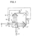
- the measuring radiation to be analyzed strikes a beam splitter 1 and is divided there into two partial radiations.
- a beam splitter 1 On the two arms of a double pendulum 2, which can oscillate freely about its axis of rotation 3, two reflector systems 4 and 4 'are attached, both of which are designed as retroreflectors insensitive to both spatial tilting and transverse offset.
- the two movable refector systems 4, 4 'each have a fixed mirror 5 and 5' opposite.
- the two partial radiations of the measuring radiation are reflected in themselves and after renewed passage through the semi-transparent beam splitter 1 to each other Interference.
- the resulting interferogram is focused in a converging lens 6 onto a detector system 7.
- the output of the detector system 7 is connected to an electronic evaluation device (not shown) in which the interferogram of the unknown measuring radiation is evaluated spectroscopically.
- the two arms of the double pendulum 2 are each an electromagnet 8 and 8 'in short distance opposite, the force effect of the double pendulum 2 in a pendulum movement, whereby the relative distance of the moving reflector systems 4, 4 'to the opposite fixed mirrors 5, 5' and also the fixed beam splitter 1 fluctuates periodically.
- the difference in the path lengths to be traversed by the two partial beams caused by this leads to the formation of an interferogram of the measuring radiation radiated into the interferometer after the two partial beams have been superimposed.
- Fig. 2 illustrates the relationship of the mechanical feed speed of the two moving reflector systems 4 and 4 ', which move when deflecting the double pendulum 2 about its axis of rotation 3 by an angle ⁇ on a circular path.
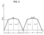
- Fig. 3 illustrates the time course of the optical feed rate over a complete pendulum phase in a conventional double pendulum interferometer.
- the electromagnet 8 (cf. Fig. 1) swings the double pendulum 2 from one side, the optical feed rate increasing steadily during this acceleration phase A.
- the electromagnet 8 is simply switched off, the double pendulum 2 retains its angular speed reached up to that point, which leads to a further increase in the optical feed speed of the moving reflector systems 4, 4 '.
- the optical feed speed reaches its maximum value, ie the deviation from the desired optical speed is greatest.
- the optical feed speed is reduced again to the desired target speed.
- the interferogram of the measuring radiation to be analyzed is recorded in a double pendulum interferometer with such an uncontrolled drive during the phase of free oscillation of the double pendulum 2 - so-called measuring phase.
- the double pendulum is braked by switching on the other electromagnet 8 'to a standstill at the reversal point U, the speed of which decreases linearly during this braking phase B.
- the double pendulum 2 is accelerated in the opposite direction due to the force of the electromagnet 8 'which is switched on until it has reached its setpoint speed M again at the beginning of the second measurement phase M.
- a laser 9 is now provided according to FIG. 1, the laser beam of which radiates into the interferometer parallel to the measurement radiation.
- This laser beam passes through the beam splitter 1, the two moving reflector systems 4, 4 'and the associated fixed mirrors 5, 5' in exactly the same optical way as the measuring radiation to be analyzed.
- a laser interferogram is produced which is masked out of the beam path by means of a small additional mirror 10 and is focused on a laser detector 11. After conversion of the optical laser interferogram into a corresponding electrical signal, the latter is fed to an electronic control unit 12. On the output side, the control unit 12 is connected to the electromagnets 8, 8 'driving the double pendulum 2'.
- the frequency of the electrical signal obtained from the laser interferogram is, as already explained above using equation (1), directly proportional to the optical feed speed V O of the reflector systems 4, 4 '.
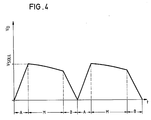
- the control unit 12 regulates it the two electromagnets 8, 8 'supplied magnetizing currents so that the deviations resulting from the circular orbit geometry and the bearing friction are completely compensated for and the optical feed rate is kept constant during the measuring phase (see FIG. 3).
- the control unit 12 contains an amplifier 13 for amplifying the interferogram signal emitted by the laser detector 11.
- a bandpass filter 14 is connected downstream to improve the signal-to-noise ratio.
- the electrical signal then passes through a frequency voltage converter 15 and an analog / digital converter 16.
- the core of the control unit 12 is a microcomputer 17, which calculates a program for controlling the electromagnets 8, 8 'from the signal emitted by the laser detector 11.
- the temporal course of the optical feed rate during a few oscillation periods of the double pendulum 2 is first stored in the memory of the microcomputer 17 and then, using the formulaic relationship between the mechanical feed rate V M and the optical feed rate V O according to equation (2) above, a program for the strength of the Magnetizing currents calculated, which are required for the controlled acceleration and deceleration of the double pendulum 2.
- the electromagnets 8, 8' are controlled.
- the frequency of the laser interferogram emitted by the laser detector 11 represents the actual optical feed rate of the moving reflector systems 4, 4 'at each point in time. This enables the in the Control unit 12 included microcomputer 17 a complete compensation of all deviations from the desired linear course of the optical feed rate of the two moving reflector systems 4, 4 ', regardless of the cause. Even with a large optical stroke or relatively slow running of the double pendulum 2, perfect spectroscopic recordings of the measuring radiation to be analyzed can thus be carried out.
- Fig. 6a shows another possibility of arranging the electromagnets 8, 8 'with respect to the double pendulum 2.
- the coils 19, 19 ' are fixed in place on the (not shown) base plate of the interferometer.
- either the magnetic core 20 or the opposite magnetic core 20 ' is more or less immersed in the coil 19 or 19'.
- the double pendulum 2 is set into the desired pendulum motion by the magnetic fields acting in the air gaps. Regardless of how far the double pendulum 2 is deflected from its rest position, the air gaps 22 between the coils 19, 19 'and the magnetic cores 20, 20' remain constant.
- Fig. 6b shows an embodiment in which the coils 23, 23 'are rigidly connected to the double pendulum 2, while the associated magnetic cores 24, 24' are stationary.
- the further embodiment of the electromagnetic system shown in FIG. 7a comprises a permanent magnet 25 which is rigidly connected to the free end of the double pendulum 2.
- this permanent magnet 25 there is a horizontal slot 26 open on both sides into which a flat coil 27 through which current flows is immersed.
- the flat coil 27 is also fastened horizontally to a holder 28. If a magnetizing current flows through the flat coil 27, the permanent magnet 25 with the double pendulum 2 rigidly attached to it rotates about the axis of rotation 3 which is stationary with respect to the base plate 29 due to the magnetic repulsion with respect to the fixed flat coil 27. When the magnetizing current in the flat coil 27 is reversed, this becomes Double pendulum 2 rotated in the opposite direction.
- FIG. 7b The vertical section shown in FIG. 7b through the plane of the rotary axis 3 (see FIG. 7a) illustrates the horizontal and mutually parallel arrangement of the double pendulum 2, permanent magnet 25 and the flat coil 27 immersing in the slot 26 thereof.
- a holder 28 is used for connection to a Base plate 29, which also carries the axis of rotation 3 of the double pendulum 2.
Landscapes
- Physics & Mathematics (AREA)
- Spectroscopy & Molecular Physics (AREA)
- General Physics & Mathematics (AREA)
- Spectrometry And Color Measurement (AREA)
Applications Claiming Priority (2)
| Application Number | Priority Date | Filing Date | Title |
|---|---|---|---|
| DE19873736694 DE3736694A1 (de) | 1987-10-29 | 1987-10-29 | Verfahren und vorrichtung zum beruehrungslosen antrieb eines doppelpendel-interferometers |
| DE3736694 | 1987-10-29 |
Publications (2)
| Publication Number | Publication Date |
|---|---|
| EP0314103A2 true EP0314103A2 (fr) | 1989-05-03 |
| EP0314103A3 EP0314103A3 (fr) | 1990-03-14 |
Family
ID=6339367
Family Applications (1)
| Application Number | Title | Priority Date | Filing Date |
|---|---|---|---|
| EP88117841A Withdrawn EP0314103A3 (fr) | 1987-10-29 | 1988-10-26 | Procédé et dispositif pour l'entraínement sans contact d'un interféromètre à pendule double |
Country Status (2)
| Country | Link |
|---|---|
| EP (1) | EP0314103A3 (fr) |
| DE (1) | DE3736694A1 (fr) |
Cited By (14)
| Publication number | Priority date | Publication date | Assignee | Title |
|---|---|---|---|---|
| DE4107549A1 (de) * | 1991-03-08 | 1992-09-10 | Deutsche Forsch Luft Raumfahrt | Verfahren zur triggerung der digitalisierung von interferogrammen und zur wellenzahlkalibrierung von interferometern nach michelson und einrichtung zu dessen durchfuehrung |
| WO1995024619A1 (fr) * | 1994-03-10 | 1995-09-14 | Opsis Ab | Interferometre et spectrometre de transformee de fourier |
| EP0702205A3 (fr) * | 1994-09-16 | 1997-01-08 | Queensgate Instr Ltd | Interféromètre |
| DE4016731C3 (de) * | 1990-05-24 | 2001-04-26 | Bruker Analytik Gmbh | Fourierspektrometer |
| WO2003078946A1 (fr) * | 2002-03-20 | 2003-09-25 | Noveltech Solutions Ltd | Interferometre |
| EP1273895A3 (fr) * | 2001-07-04 | 2005-01-19 | Leica Microsystems Semiconductor GmbH | Appareil de mesure interférométrique pour le calibrage de longueurs d'onde |
| WO2008083492A1 (fr) * | 2007-01-12 | 2008-07-17 | Abb Bomem Inc. | Interféromètre à deux faisceaux pour une spectroscopie par transformée de fourier avec un mécanisme de balayage à double pivot |
| CN102221433A (zh) * | 2011-05-31 | 2011-10-19 | 哈尔滨工业大学 | 多普勒振镜正弦调制多光束激光外差二次谐波测量微冲量的方法 |
| CN102564587A (zh) * | 2012-01-11 | 2012-07-11 | 天津港东科技发展股份有限公司 | 旋转式倍光程干涉仪 |
| CN104457988A (zh) * | 2014-12-18 | 2015-03-25 | 武汉宇虹环保产业发展有限公司 | 一种红外光谱测量装置 |
| CN104568152A (zh) * | 2014-12-29 | 2015-04-29 | 中国科学院西安光学精密机械研究所 | 横向剪切干涉扫描傅里叶变换成像光谱仪 |
| CN105318969A (zh) * | 2015-10-13 | 2016-02-10 | 西安应用光学研究所 | 基于双平面直角反射镜的红外干涉成像光谱仪 |
| CN115389445A (zh) * | 2022-10-27 | 2022-11-25 | 杭州泽天春来科技有限公司 | 傅里叶红外干涉仪的控制方法、系统及可读存储介质 |
| CZ309439B6 (cs) * | 2009-04-30 | 2023-01-18 | Český metrologický institut | Fourierova spektroskopie s rozlišením zubů frekvenčního hřebene |
Families Citing this family (8)
| Publication number | Priority date | Publication date | Assignee | Title |
|---|---|---|---|---|
| US5159405A (en) * | 1989-10-28 | 1992-10-27 | Horiba, Ltd. | Multibeam interferometer for use in a fourier transform spectrometer and a driving device for moving the mirrors used therein |
| DE59100331D1 (de) * | 1990-02-21 | 1993-10-07 | Deutsche Forsch Luft Raumfahrt | Interferometer nach Michelson zur Erzeugung optischer Wegunterschiede. |
| CA2038880C (fr) * | 1990-09-29 | 2001-01-02 | Osamu Yoshikawa | Interferometre a deux faisceaux |
| FI107358B (fi) * | 1993-06-17 | 2001-07-13 | Temet Instr Oy | Fokusoiva interferometri |
| FI107357B (fi) * | 1993-06-17 | 2001-07-13 | Temet Instr Oy | Pyyhkäisevä interferometri |
| FI102011B1 (fi) * | 1994-10-10 | 1998-09-30 | Jyrki Kauppinen | Interferometri |
| DE102006037967B3 (de) * | 2006-08-14 | 2007-08-23 | Siemens Ag | Michelson-Interferometer |
| CN114397018B (zh) * | 2021-12-30 | 2023-08-01 | 杭州春来科技有限公司 | 可调的光谱纠正系统及方法 |
Family Cites Families (4)
| Publication number | Priority date | Publication date | Assignee | Title |
|---|---|---|---|---|
| US3809481A (en) * | 1972-12-01 | 1974-05-07 | Nasa | Single reflector interference spectrometer and drive system therefor |
| US4193693A (en) * | 1978-02-24 | 1980-03-18 | Nasa | Velocity servo for continuous scan Fourier interference spectrometer |
| DE3005520C2 (de) * | 1980-02-14 | 1983-05-05 | Kayser-Threde GmbH, 8000 München | Zweistrahl-Interferometer zur Fourierspektroskopie |
| US4575246A (en) * | 1984-03-05 | 1986-03-11 | Japan Spectroscopic Co., Ltd. | Michelson interferometer |
-
1987
- 1987-10-29 DE DE19873736694 patent/DE3736694A1/de not_active Ceased
-
1988
- 1988-10-26 EP EP88117841A patent/EP0314103A3/fr not_active Withdrawn
Cited By (19)
| Publication number | Priority date | Publication date | Assignee | Title |
|---|---|---|---|---|
| DE4016731C3 (de) * | 1990-05-24 | 2001-04-26 | Bruker Analytik Gmbh | Fourierspektrometer |
| DE4107549A1 (de) * | 1991-03-08 | 1992-09-10 | Deutsche Forsch Luft Raumfahrt | Verfahren zur triggerung der digitalisierung von interferogrammen und zur wellenzahlkalibrierung von interferometern nach michelson und einrichtung zu dessen durchfuehrung |
| WO1995024619A1 (fr) * | 1994-03-10 | 1995-09-14 | Opsis Ab | Interferometre et spectrometre de transformee de fourier |
| US5650848A (en) * | 1994-03-10 | 1997-07-22 | Opsis Ab | Interferometer compensation for displacement inaccuracies during path length difference altering, method therefor, and fourier transform spectrometer using the same |
| EP0702205A3 (fr) * | 1994-09-16 | 1997-01-08 | Queensgate Instr Ltd | Interféromètre |
| EP1273895A3 (fr) * | 2001-07-04 | 2005-01-19 | Leica Microsystems Semiconductor GmbH | Appareil de mesure interférométrique pour le calibrage de longueurs d'onde |
| WO2003078946A1 (fr) * | 2002-03-20 | 2003-09-25 | Noveltech Solutions Ltd | Interferometre |
| US7280217B2 (en) | 2002-03-20 | 2007-10-09 | Noveltech Solutions Ltd. | Interferometer utilizing a rotating rigid structure |
| WO2008083492A1 (fr) * | 2007-01-12 | 2008-07-17 | Abb Bomem Inc. | Interféromètre à deux faisceaux pour une spectroscopie par transformée de fourier avec un mécanisme de balayage à double pivot |
| CZ309439B6 (cs) * | 2009-04-30 | 2023-01-18 | Český metrologický institut | Fourierova spektroskopie s rozlišením zubů frekvenčního hřebene |
| CN102221433A (zh) * | 2011-05-31 | 2011-10-19 | 哈尔滨工业大学 | 多普勒振镜正弦调制多光束激光外差二次谐波测量微冲量的方法 |
| CN102221433B (zh) * | 2011-05-31 | 2013-02-13 | 哈尔滨工业大学 | 多普勒振镜正弦调制多光束激光外差二次谐波测量微冲量的方法 |
| CN102564587A (zh) * | 2012-01-11 | 2012-07-11 | 天津港东科技发展股份有限公司 | 旋转式倍光程干涉仪 |
| CN102564587B (zh) * | 2012-01-11 | 2013-08-28 | 天津港东科技发展股份有限公司 | 旋转式倍光程干涉仪 |
| CN104457988A (zh) * | 2014-12-18 | 2015-03-25 | 武汉宇虹环保产业发展有限公司 | 一种红外光谱测量装置 |
| CN104568152A (zh) * | 2014-12-29 | 2015-04-29 | 中国科学院西安光学精密机械研究所 | 横向剪切干涉扫描傅里叶变换成像光谱仪 |
| CN104568152B (zh) * | 2014-12-29 | 2017-02-22 | 中国科学院西安光学精密机械研究所 | 横向剪切干涉扫描傅里叶变换成像光谱仪 |
| CN105318969A (zh) * | 2015-10-13 | 2016-02-10 | 西安应用光学研究所 | 基于双平面直角反射镜的红外干涉成像光谱仪 |
| CN115389445A (zh) * | 2022-10-27 | 2022-11-25 | 杭州泽天春来科技有限公司 | 傅里叶红外干涉仪的控制方法、系统及可读存储介质 |
Also Published As
| Publication number | Publication date |
|---|---|
| DE3736694A1 (de) | 1989-06-01 |
| EP0314103A3 (fr) | 1990-03-14 |
Similar Documents
| Publication | Publication Date | Title |
|---|---|---|
| DE3736694A1 (de) | Verfahren und vorrichtung zum beruehrungslosen antrieb eines doppelpendel-interferometers | |
| DE69302749T2 (de) | Verfahren zum Justieren einer kontinuierlich abstimmbaren Lichtquelle | |
| EP0242407A2 (fr) | Dispositif pour la mesure de petites longueurs | |
| DE2407042A1 (de) | Verfahren und vorrichtung zum messen des durchmessers, der unrundheit oder von schwingungen eines gegenstandes | |
| EP0229243A1 (fr) | Dispositif de mesure de la forme d'une surface le long d'une ligne de palpation | |
| DE2828160B2 (de) | Elektromagnetische Rühreinrichtung für Stranggießanlagen | |
| EP0236777A1 (fr) | Appareil de mesure et de positionnement | |
| DE2847716A1 (de) | Rotierkopf zum pruefen von langgestrecktem ferromagnetischem pruefgut | |
| DE2528293A1 (de) | Geradlauf-regeleinrichtung | |
| DE2704320B2 (de) | Einrichtung zur Bestimmung des Torsionswinkels eines Rotationsviskosimeters | |
| DE2746279B2 (de) | Schwingungsmeßgerät | |
| DE1755720C3 (de) | Einrichtung an fahrbaren Maschinen zur Anzeige, Aufnahme und/oder Korrektur der Lage eines Gleises | |
| DE4132724C2 (de) | Vorschubgerät | |
| DD150111A1 (de) | Einrichtung zur weg-kraft-koordinierung an antastsystemen | |
| DE69222011T2 (de) | Röntgenanalysegerät | |
| DE2800340C2 (de) | Einstellvorrichtung, insbesondere für optische Messungen | |
| DE3432842A1 (de) | X-y-flaechenantrieb mit begrenzter (phi)-drehung und z-verschiebung | |
| DE2604666A1 (de) | Monochromator zur nutzung zweier wellenlaengen | |
| DE2446936A1 (de) | Regelanordnung zur dynamischen entkopplung eines schienengebundenen fahrzeuges, das gegenueber seinen schienen mit hilfe von magneten in einem abstand gefuehrt ist | |
| DE19952389B4 (de) | Verfahren zur Bestimmung der Parameter und/oder Strom-Weg-Kennlinie eines elektrisch angetriebenen Motorsystems | |
| DD288872A5 (de) | Einkoordinatenmessgeraet | |
| DE19519929C2 (de) | Verfahren und Vorrichtung zum Ausrichten einer Drahtelektrode in einer Funkenerosionsmaschine | |
| EP0512356A2 (fr) | Système de mesure | |
| DE639212C (de) | Registrierendes Spektralphotometer | |
| DE4027321A1 (de) | Dreikoordinatenmessgeraet |
Legal Events
| Date | Code | Title | Description |
|---|---|---|---|
| PUAI | Public reference made under article 153(3) epc to a published international application that has entered the european phase |
Free format text: ORIGINAL CODE: 0009012 |
|
| AK | Designated contracting states |
Kind code of ref document: A2 Designated state(s): AT BE CH DE ES FR GB GR IT LI LU NL SE |
|
| RAP1 | Party data changed (applicant data changed or rights of an application transferred) |
Owner name: ERWIN KAYSER-THREDE GMBH |
|
| PUAL | Search report despatched |
Free format text: ORIGINAL CODE: 0009013 |
|
| AK | Designated contracting states |
Kind code of ref document: A3 Designated state(s): AT BE CH DE ES FR GB GR IT LI LU NL SE |
|
| STAA | Information on the status of an ep patent application or granted ep patent |
Free format text: STATUS: THE APPLICATION HAS BEEN WITHDRAWN |
|
| 18W | Application withdrawn |
Withdrawal date: 19900523 |