EP0314177A2 - Transmetteur pour système de commande à distance et méthode pour commander à distance plusieurs opérations à plusieurs appareils électroniques - Google Patents
Transmetteur pour système de commande à distance et méthode pour commander à distance plusieurs opérations à plusieurs appareils électroniques Download PDFInfo
- Publication number
- EP0314177A2 EP0314177A2 EP88118032A EP88118032A EP0314177A2 EP 0314177 A2 EP0314177 A2 EP 0314177A2 EP 88118032 A EP88118032 A EP 88118032A EP 88118032 A EP88118032 A EP 88118032A EP 0314177 A2 EP0314177 A2 EP 0314177A2
- Authority
- EP
- European Patent Office
- Prior art keywords
- signal
- transmitter
- key
- response
- display
- Prior art date
- Legal status (The legal status is an assumption and is not a legal conclusion. Google has not performed a legal analysis and makes no representation as to the accuracy of the status listed.)
- Withdrawn
Links
- 238000000034 method Methods 0.000 title claims description 23
- 230000005540 biological transmission Effects 0.000 claims abstract description 29
- 230000004044 response Effects 0.000 claims abstract description 14
- 230000003287 optical effect Effects 0.000 claims description 6
- 238000010586 diagram Methods 0.000 description 9
- 230000008569 process Effects 0.000 description 7
- 230000008859 change Effects 0.000 description 5
- 230000004048 modification Effects 0.000 description 3
- 238000012986 modification Methods 0.000 description 3
- 230000001419 dependent effect Effects 0.000 description 2
- 238000003491 array Methods 0.000 description 1
- 238000010276 construction Methods 0.000 description 1
- 230000007423 decrease Effects 0.000 description 1
- 230000007547 defect Effects 0.000 description 1
- 239000004973 liquid crystal related substance Substances 0.000 description 1
- 238000004519 manufacturing process Methods 0.000 description 1
- 238000005070 sampling Methods 0.000 description 1
- 238000007493 shaping process Methods 0.000 description 1
Images


Classifications
-
- H—ELECTRICITY
- H04—ELECTRIC COMMUNICATION TECHNIQUE
- H04B—TRANSMISSION
- H04B1/00—Details of transmission systems, not covered by a single one of groups H04B3/00 - H04B13/00; Details of transmission systems not characterised by the medium used for transmission
- H04B1/06—Receivers
- H04B1/16—Circuits
- H04B1/20—Circuits for coupling gramophone pick-up, recorder output, or microphone to receiver
- H04B1/202—Circuits for coupling gramophone pick-up, recorder output, or microphone to receiver by remote control
-
- G—PHYSICS
- G08—SIGNALLING
- G08C—TRANSMISSION SYSTEMS FOR MEASURED VALUES, CONTROL OR SIMILAR SIGNALS
- G08C2201/00—Transmission systems of control signals via wireless link
- G08C2201/20—Binding and programming of remote control devices
-
- G—PHYSICS
- G08—SIGNALLING
- G08C—TRANSMISSION SYSTEMS FOR MEASURED VALUES, CONTROL OR SIMILAR SIGNALS
- G08C2201/00—Transmission systems of control signals via wireless link
- G08C2201/90—Additional features
- G08C2201/92—Universal remote control
Definitions
- the present invention generally relates to a transmitter of a remote control system for use with a TV receiver, a video tape recorder and other associated apparatuses, and more particularly, to a transmitter of a remote control system wherein the user is allowed to modify an array of operation keys for easier operation thereof, as well as to a method of remotely controlling a plurality of operations on a plurality of electronic devices.
- the remote control system includes a transmitter for manual use.
- the receiver of the remote control system is incorporated into the above-described electronic devices.
- an optical signal corresponding to the manipulation is sent from the transmitter, to the receiver.
- a power source, a channel selection unit, a sound volume unit and other adjusting units are adjustably controlled.
- the transmitter of such a remote control system is typically composed of operation keys, a transmission code generating means for generating the transmission codes of information corresponding to the operation keys by pushing down the keys and outputting means for outputting the transmission codes from the transmission code generating means to the outside.
- the thus constructed remote control systems are provided to exhibit one-to-one correspondence to the above-described electronic devices. For instance, if there are three units such as, a TV receiver, a video tape recorder and a laser disc player, three remote control systems are needed correspondingly.
- the arrangement, which requires as many as three transmitters, is inconvenient for the user who has to operate each of transmitters by holding them one after another.
- a transmitter of a first remote control system having an arrangement such that transmission data of the transmitter of a second remote control system can be stored thereon after effecting a sampling process, so that the transmission data of the second system as well as the transmission data of the first remote control system can be transmitted.
- transmission data to be transmitted is confined to the data of the operation keys provided in the first transmitter so that it is impossible to transmit data of other operation keys designed for other transmitters.
- the arrays of the operation keys are all determined on the part of the markers so that it is impossible to modify the array of keys in accordance with the user's choice.
- the present invention provides a transmitter of a remote control system, including: transmission code generating means for generating transmission codes of information corresponding to operation keys said codes being generated by pushing down the operation keys; and outputting means for outputting the transmission code from the transmission code generating means to the outside; a correspondence table for making a physical position of the operation key correspond to the information of the operation keys in the physical position; signal processing means for imparting both the physical position when pushing down the operation keys and the information of the operation keys which has been obtained from the correspondence table to the transmission code generating means as operation key correspondence information; and program mode processing means for modifying a correspondence relation of the correspondence table on the basis of data transmitted from an external inputting unit including the operation keys in a predetermined program mode provided in conformity with a command from a command inputting unit for issuing a program mode command.
- the operation keys when transmitting a normal control signal, the operation keys are first pushed down.
- the information corresponding to the operation keys, which is obtained from the correspondence table, is imparted to the signal processing means.
- the program mode processing means is set in the associated program mode by the program mode command from the command inputting unit.
- the data on the modification of key position or on the modification of key information is inputted from the external inputting unit including the operation keys, whereby a correspondence relation of the correspondence table can be varied on the basis of the thus inputted data.
- the program mode processing means is set in the associated program mode by issuing a program mode command from the command inputting unit.
- the subsequent step is to modify the operation key correspondence information within the correspondence table which corresponds to the single operation key by inputting the control data for controlling a variety of apparatuses from the external inputting unit including the operation keys.
- the user is allowed to modify the array of operation keys for easier operation thereof, and the plurality of electronic units can be controlled by a single operation key.
- this facilitates the use of the transmitter and contributes to the miniaturization in configuration of the transmitter in spite of the fact that a plurality of electronic units can be controlled. Further details and advantages of the transmitter of the invention will become evident from the following description of the enclosed drawings.
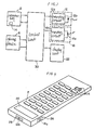
- the transmitter in the embodiment depicted in of FIG. 1 includes a storage device 6 for storing a correspondence table stores information which corresponds to the position of operation keys 2.
- a signal processing means 8 outputs, as a portion of operation key correspondence information S DD , both information SF regarding physical position of the operation keys 2 and a piece of information S D corresponding to this physical position of the operation keys 2 which is obtained from the correspondence table 4 of the storage device 6.
- Transmission code generating means 10 generates transmission codes of the operation key correspondence information S DD outputted from the signal processing means 8.
- Output unit 12 outputs the transmission codes coming from the transmission codes generating means 10 to the outside.
- a command input unit 14 issues a program mode command.
- An external input unit 18 which includes the operation keys 2 and a data input circuit 16 is set in a predetermined program mode provided in conformity with the command issued from the command input unit 14.
- Program mode processing means 20 modifies the correspondence relation of the correspondence table 4 on the basis of data sent from the external input unit 18.
- a display unit 22 is display-controlled by the signal processing means 8 and the program mode processing means 20.
- a control unit 30 includes the signal processing means 8, the transmission code generating means 10 and program mode processing means 20.
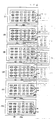
- the correspondence table 4 employed in the transmitter of the remote control system is, as illustrated in FIG. 2, formed of key position information addresses 4a having one-to-one correspondence to the physical positions (defined by, e.g., a column M of keys and a row N of keys) of the operation keys 2 and of pieces of coded information S D of the operation keys 2 which are to be stored in sequence, corresponding to the key position information addresses 4a.
- the transmitter of the remote control system is constructed in the following manner.
- the operation keys 2 are connected to the control unit 30 to which the data inputting circuit is linked.
- the operation keys 2 and the data input circuit 16 are combined to constitute external input unit 18.
- the data input circuit 16 includes an input circuit 16b for receiving a signal from a light receiving diode 16a and shaping a waveform thereof to obtain a predetermined signal.
- This input circuit 16b further supplies this signal to the control unit 30 to which the output means 12 is connected.
- the output means 12 is so arranged that a light emitting diode 12b is caused to emit infrared-rays in response to a signal transmitted from an output circuit 12a for amplifying and output the transmission codes sent from the control unit 30, thereby output an optical signal.
- the control unit 30 is further connected to the display unit 22 and to the storage device 6. Stored in this storage device 6 is a program for permitting a CPU of the control unit to function.
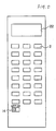
- the transmitter of the remote control system has a thin rectangular configuration and has its surface provided with the operations keys, the display unit 22 and a switch of the command inputting unit 14.
- One side surface of the transmitter is formed with a window 26 for admitting the optical signal to the light receiving diode 16a of the data input circuit 16 and with a window 28 for output the optical signal from the light emitting diode 12b of the output means 12 to the outside.
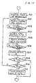
- the control unit 30 determines whether the command input unit 14 is turned ON or OFF (100). If input unit 14 is turned OFF, no processing is performed and the processing comes to an end. If turned ON, however, the processing moves to a subsequent step 101, wherein the control unit 30 makes a decision to select and execute the specific processing corresponding to a given key 2 which has been pushed. If no key 2 is pushed even after a predetermined time has passed, the operations of a plurality of electronic units are controlled by manipulating a single operation key among the operation keys 2. If the given key among the operation keys 2 is pushed before the predetermined time passes, there are performed functions to modify the key array depending on the type of key pushed (steps 103 and 104).
- Any one of program modes is selected by executing the above-described operations.
- the control units works, and the program mode processing means 20 is actuated.
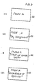
- the program mode processing means 20 causes the display unit 22 to display the one key operation setting mode (200). Then, as illustrated in FIG. 8(I), the one key operation setting mode "A" is displayed. This display continues with no change till this mode is varied. Subsequently, the program mode processing means 20 causes the display unit 22 to display "key assignment" to determine the specific key by which a plurality of electronic units are controlled (201). As depicted in FIG. 8(II), "key assignment" is displayed on the display unit 22. A subsequent step is to wait for key inputting (202).
- the program mode processing means 20 further causes the display unit 22 to display "control data inputting” in order to input the control data of a transmitting destination device (204). As a result, "control data inputting” is, as illustrated in FIG. 8(III), displayed on the display unit 22. Then, the program mode processing means 20 waits for data to be input (205).
- the inputting of control data involves (1) a method of effecting the inputting process in the form of code by employing the operation keys 2, (2) a method of effecting the inputting process in terms of function by using the operation keys 2 and (3) a method of inputting the control data sent from the transmitter of other remote control system through the light receiving diode 16a of the data inputting circuit 16. Therefore, after the control data is input in the step 205, the control data is stored in a predetermined area of the correspondence table 4 of the storage device 6 by the program mode processing means 20 (206). It is then determined whether the command inputting unit 14 is turned OFF or ON (207). If turned ON, the processing moves to a step (208). If turned OFF, the processing is terminated.
- the program mode processing means 20 determines whether a predetermined storage area of the correspondence table 4 of the storage device 6 is full of data. If full, the processing proceeds to a step 209. If not, the processing returns to the step 205 to set the control data of the next apparatus. In a step 209, the program mode processing means 20 causes the display unit 22 to display, as illustrated in FIG. 8(IV), "incapable of setting", thus terminating the processing.
- the command inputting unit 14 is turned 0FF, and the transmitter of the remote control system is used. At this time, it is possible to control the first, second and third electronic units simply by pushing down any one of operation keys 2.
- the control unit 30 functions, and the program mode processing means 2 for the key array modifying operation 1 is also actuated.
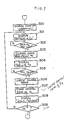
- the program mode processing means 20 first causes the display unit 22 to indicate that the mode is an operation mode of the key array modifying operation 1 (300).
- an operation mode "B" of the key array modifying operation 1 is displayed. The display continues with no change till the mode is varied.
- the program mode processing means 20 makes the display unit 22 display "setting of key K1".
- the processing waits for key-inputting of the key K1 (302).
- the key K1 is assigned, the physical position 'of the key K1 is determined.
- the control data is read from the area in the storage position of the correspondence table 4 which corresponds to the physical position thereof (303).
- the program mode processing means 20 makes the display unit 22 display "setting of key position K2" indicating that the key position K2 is to be set (304). As shown in FIG. 10(III), "setting of key position K2" is displayed thereon. Next the processing waits for key-inputting of the key position K2 (305). When the key position K2 is inputted, the program mode processing means 20 reads the control data that has stored so far, of the correspondence table 4 in the key position K2. Subsequently, the program mode processing means 20 writes the control data (306) read in the step 303. Upon completion of this writing process, the control data red from the key position K2 is stored in the storage area in the key position K1 of the correspondence table 4 (307). The program mode processing means 20 causes the display unit 22 to indicate that the setting has ended (308). Then, as shown in FIG. 10(IV), "end of setting" is displayed on the display unit 22.
- the next step is to determine whether the command inputting unit 14 is turned OFF or ON (309). If turned OFF, the processing comes to an end. If turned ON, the processing goes back to step 301.
- the operations are thus carried out, and hence the specific key K1 can be changed over to the position K2.
- the key is in the position K1 before being shifted.
- the control unit 30 works, and the program mode processing means 20 of the key array modifying operation 2 is also actuated.
- the program mode processing means 20 makes the display unit 22 indicate that the mode is an operation mode of the key array modifying operation 2 (400).
- an operation mode "C" of the key array modifying operation 2 is displayed. This display continues without being changed till this mode is varied.
- the program mode processing means 20 causes the display unit 22 to display "setting of key K” indicating that the key K is to be set (401). Then, as illustrated in FIG. 12(II), "setting of key K” is displayed on the display unit 22. A subsequent step is to wait for key-inputting of the key K (402).
- the program mode processing mean 20 functions to make the display unit 22 indicate "inputting of control data” showing that the control data of the key to be modified is inputted (403).
- a subsequent step is to judge whether the command inputting unit 14 is turned OFF or ON 407). If turned OFF, the processing is terminated. If turned ON, the processing returns to the step 401.
- a liquid crystal display plate 22a is provided as the display unit 22 beneath the touch panel 2a; and side surfaces thereof are formed with windows 26 and 28, though these windows are not shown in the Figure.
- the control unit 30 works, and the program mode processing means 20 for setting the key operation is also actuated.
- the program mode processing means 20 causes the display unit 22 to indicate that the mode is a key operation setting mode (501) (see Fig. 15). As shown in FIG. 16(I), a key operation setting mode "P1" is flash-displayed. The on-and-off display continues with no change till this mode is varied.
- the program mode processing means 20 causes the display unit 22 to flash-display all the keys at a different cycles excluding the keys P1 to P4.
- the next step is to wait for the key inputting (503).
- a physical position of the key 2 is judged preparatory to the step of storing in table 4 data which corresponds to this physical position (504).
- the assigned key alone is, as shown in FIG. 16(III), flash-displayed.
- the program mode processing means 20 causes the display unit 22 to flash-display the key P4 together with the P1 among the operation keys 2 (505). Consequently, both the key P1 and the key P4 are, as illustrated in FIG. 16(III), flash-displayed. Then the program mode processing means 20 waits for the data-inputting (506).
- the inputting of the control data is the same as that in the first embodiment, and hence the description is omitted.
- the control data is stored in a predetermined area of the correspondence table 4 of the storage device 6 by use of the program mode processing means 20 (507). A subsequent step is to judge whether the command inputting unit 14 is turned OFF or ON.
- the processing moves to a step 509. If turned OFF, the processing comes to an end (508).
- the program mode processing means 20 judges whether a predetermined storage area of the correspondence table 4 of the storage device 6 is full of data or not. If full, the processing proceeds to a step 510. If not, the processing returns to step 502 to set the control data of the next apparatus.
- the program mode processing means 20 causes the display unit 22 to flash-display all the keys P1 to P4 among the operation keys 2, thus finishing the processing.
- the present area of the correspondence table 4 shown in FIG. 2 is stored consecutively with the control data of the first, second and third electronic devices in sequence of input.
- the first, second and third electronic devices can be controlled simply by pushing down any one of the operation keys 2.
- the control unit 30 functions, and the program mode processing means 20 of the key array modifying operation is also actuated.
- the program mode processing means 20 at first makes the display unit 22 indicate that the mode is an operation mode of the key array modifying operation 1 (600). As is shown in FIG. 18(I), the key P2 among the operation keys 2 in the operation mode of the key array modifying operation 1 is flash-displayed. The display remains as it is without being changed till the mode is varied.
- program mode processing means 20 causes the display unit 22 to flash-display all the keys excluding the keys P1 through P4 among the operation keys 2-at a different cycle from that of the key P2 (601). All the keys except the keys P1 through P4 among the operation keys 2 are, as depicted in FIG. 18(II), flash-displayed on the display unit 22 and it follows that the program mode processing means 20 waits for key-inputting of the key K1 (602).
- the key K1 is assigned, the physical position of the key K1 is judged.
- the control data is read from an area in the storage position of the correspondence table 4 which corresponds to the physical position.
- the key K1 is indicated by e.g., a black-off character, and the on-and-off display of the operation keys 2 ceases (603). Then the appearance on the display unit 22 is depicted in FIG. 18(III).
- the program mode processing means 20 causes the display unit 22 to flash-display all the keys excluding the keys P1 to P4 and also the key K1 indicated by the black-off character among the operation keys 2 at a different cycle from that of the key P2 (604). As shown in FIG. 18(IV), the display unit 22 then flash-displays all the keys except the keys P1 to P4 and the key K1 drawn with the black-off character among the operation keys 2 at the different cycle from that of the key P2. The program mode processing means 20 waits for the inputting of the key in the key position K2 (605).
- the program mode processing means 20 reads the control data which has been stored so far in the storage area of the correspondence table 4 which corresponds to the key position K2, then writes the control data read in the step 603 to the storage area of the correspondence table 4. Simultaneously, the on-and-off display of the operation keys 2 and the black-off display of the key K1 are stopped. Instead, the key position K2 is displayed with the black-off character (606). After these processes have been done, the control data read from the key position K2 is stored in the storage area in the position of the K1 of the correspondence table 4 (607). The program mode processing means 20 makes the display unit 22 indicate that the setting has been finished (608). As depicted in FIG.
- the display unit 22 flash-displays all the keys P1 through P4 among the operation keys 2 at a different cycle from that when the setting is unpracticable during a given period. After the on-and-off display has come to an end, the black-off display of the key position K2 is halted. Then there is given the information that the setting has been finished.
- the key array modifying operation 2 (operation of step 104) can be attained on the basis of the on-and-off display described above.
- FIG. 19 there is illustrated still another embodiment.
- the inputting unit 18 is composed simply of the operation keys 2.
- the number of manufacturing processes decreases, the construction is facilitated by of eliminating the processing means, although it is unfeasible to directly fetch and set the transmission codes from the transmitter of other remote control system.
- the transmitter can advantageously be provided at a low cost.
- the command inputting unit 14 is set by pushing down the specific key among the operation keys 2 in cooperation with the program mode switch.
- the arrangement is not limited to this one.
- the program mode switches may be provided, corresponding to the program mode to be processed; or alternatively the program mode display on the display unit 22 may be varied by continuously pushing down the single program mode switch.
- the user is allowed to modify the array of operation keys for easier operation thereof, and the plurality of electronic devices can be controlled by the single key.
- the operation of the transmitter can be remarkably facilitated, the transmitter can be miniaturized in outer configuration despite the plurality of electronic devices to be controlled.
- the user can modify the array of operation keys to obtain easier manipulation.
- the plurality of electronic devices can be controlled by the single key, thereby considerably facilitating the use of transmitter.
- the transmitter can be smaller in spite of the fact that the plurality of electronic devices can be controlled.
Landscapes
- Engineering & Computer Science (AREA)
- Computer Networks & Wireless Communication (AREA)
- Signal Processing (AREA)
- Selective Calling Equipment (AREA)
Applications Claiming Priority (2)
| Application Number | Priority Date | Filing Date | Title |
|---|---|---|---|
| JP27535587A JPH01117595A (ja) | 1987-10-30 | 1987-10-30 | 遠隔制御装置の送信機 |
| JP275355/87 | 1987-10-30 |
Publications (2)
| Publication Number | Publication Date |
|---|---|
| EP0314177A2 true EP0314177A2 (fr) | 1989-05-03 |
| EP0314177A3 EP0314177A3 (fr) | 1990-12-19 |
Family
ID=17554318
Family Applications (1)
| Application Number | Title | Priority Date | Filing Date |
|---|---|---|---|
| EP19880118032 Withdrawn EP0314177A3 (fr) | 1987-10-30 | 1988-10-28 | Transmetteur pour système de commande à distance et méthode pour commander à distance plusieurs opérations à plusieurs appareils électroniques |
Country Status (2)
| Country | Link |
|---|---|
| EP (1) | EP0314177A3 (fr) |
| JP (1) | JPH01117595A (fr) |
Cited By (12)
| Publication number | Priority date | Publication date | Assignee | Title |
|---|---|---|---|---|
| DE4024733A1 (de) * | 1989-08-04 | 1991-02-07 | Futaba Denshi Kogyo Kk | Kommandosender |
| FR2674353A1 (fr) * | 1991-03-19 | 1992-09-25 | Pioneer Electronic Corp | Systeme de commande a distance pour un systeme audio/video. |
| EP0566516A1 (fr) * | 1992-04-13 | 1993-10-20 | International Business Machines Corporation | Appareil de télécommande multimode avec désignations des touches de clavier modifiable électriquement |
| EP0577267A1 (fr) * | 1992-06-18 | 1994-01-05 | Sony Corporation | Contrôleur de télécommande et méthodes pour régler sélectivement des signaux de télécommande |
| US5287210A (en) * | 1992-01-13 | 1994-02-15 | Siavash Sefidvash | Smart infrared controller |
| EP0613606A4 (fr) * | 1991-11-19 | 1995-05-10 | Scientific Atlanta | Procede et appareil de communication de signaux de donnees de programme par l'intermediaire d'une unite de commande a distance. |
| EP0697689A3 (fr) * | 1994-08-11 | 1996-07-24 | Int Computers Ltd | Ordinateur et télévision intégrés |
| US5552917A (en) * | 1987-10-14 | 1996-09-03 | Universal Electronics Inc. | Remote control |
| EP0616456A3 (en) * | 1993-02-19 | 1997-02-26 | Canon Kk | Multimedia communication system, transmitter and receiver therefor. |
| US6587067B2 (en) | 1987-10-14 | 2003-07-01 | Universal Electronics Inc. | Universal remote control with macro command capabilities |
| WO2005043484A1 (fr) * | 2003-11-04 | 2005-05-12 | Koninklijke Philips Electronics N.V. | Dispositif de telecommande universelle a ecran tactile |
| US7370532B2 (en) | 2002-01-11 | 2008-05-13 | Lockheed Martin Corporation | RF communications method and system for laser ultrasonic testing |
Families Citing this family (1)
| Publication number | Priority date | Publication date | Assignee | Title |
|---|---|---|---|---|
| JP4919705B2 (ja) * | 2006-06-01 | 2012-04-18 | 三洋電機株式会社 | デジタルテレビ放送受信機 |
Family Cites Families (2)
| Publication number | Priority date | Publication date | Assignee | Title |
|---|---|---|---|---|
| US4623887A (en) * | 1984-05-15 | 1986-11-18 | General Electric Company | Reconfigurable remote control |
| US4626848A (en) * | 1984-05-15 | 1986-12-02 | General Electric Company | Programmable functions for reconfigurable remote control |
-
1987
- 1987-10-30 JP JP27535587A patent/JPH01117595A/ja active Pending
-
1988
- 1988-10-28 EP EP19880118032 patent/EP0314177A3/fr not_active Withdrawn
Cited By (15)
| Publication number | Priority date | Publication date | Assignee | Title |
|---|---|---|---|---|
| US6587067B2 (en) | 1987-10-14 | 2003-07-01 | Universal Electronics Inc. | Universal remote control with macro command capabilities |
| US5552917A (en) * | 1987-10-14 | 1996-09-03 | Universal Electronics Inc. | Remote control |
| DE4024733A1 (de) * | 1989-08-04 | 1991-02-07 | Futaba Denshi Kogyo Kk | Kommandosender |
| FR2674353A1 (fr) * | 1991-03-19 | 1992-09-25 | Pioneer Electronic Corp | Systeme de commande a distance pour un systeme audio/video. |
| EP0613606A4 (fr) * | 1991-11-19 | 1995-05-10 | Scientific Atlanta | Procede et appareil de communication de signaux de donnees de programme par l'intermediaire d'une unite de commande a distance. |
| US5287210A (en) * | 1992-01-13 | 1994-02-15 | Siavash Sefidvash | Smart infrared controller |
| US5450079A (en) * | 1992-04-13 | 1995-09-12 | International Business Machines Corporation | Multimodal remote control device having electrically alterable keypad designations |
| EP0566516A1 (fr) * | 1992-04-13 | 1993-10-20 | International Business Machines Corporation | Appareil de télécommande multimode avec désignations des touches de clavier modifiable électriquement |
| US5485149A (en) * | 1992-06-18 | 1996-01-16 | Sony Corporation | Remote controller and method for assigning to signals priority based on type and manufacture of equipment |
| EP0577267A1 (fr) * | 1992-06-18 | 1994-01-05 | Sony Corporation | Contrôleur de télécommande et méthodes pour régler sélectivement des signaux de télécommande |
| EP0616456A3 (en) * | 1993-02-19 | 1997-02-26 | Canon Kk | Multimedia communication system, transmitter and receiver therefor. |
| US5640195A (en) * | 1993-02-19 | 1997-06-17 | Canon Kabushiki Kaisha | Multimedia communication system, multimedia information transmitting apparatus and multimedia information receiving apparatus |
| EP0697689A3 (fr) * | 1994-08-11 | 1996-07-24 | Int Computers Ltd | Ordinateur et télévision intégrés |
| US7370532B2 (en) | 2002-01-11 | 2008-05-13 | Lockheed Martin Corporation | RF communications method and system for laser ultrasonic testing |
| WO2005043484A1 (fr) * | 2003-11-04 | 2005-05-12 | Koninklijke Philips Electronics N.V. | Dispositif de telecommande universelle a ecran tactile |
Also Published As
| Publication number | Publication date |
|---|---|
| JPH01117595A (ja) | 1989-05-10 |
| EP0314177A3 (fr) | 1990-12-19 |
Similar Documents
| Publication | Publication Date | Title |
|---|---|---|
| US5228077A (en) | Remotely upgradable universal remote control | |
| US4807052A (en) | Remotely controllable electronic apparatus | |
| US5255313A (en) | Universal remote control system | |
| US6998997B2 (en) | System and method for learning macro routines in a remote control | |
| EP0314177A2 (fr) | Transmetteur pour système de commande à distance et méthode pour commander à distance plusieurs opérations à plusieurs appareils électroniques | |
| US6195033B1 (en) | Key mover | |
| KR100705307B1 (ko) | 범용 원격 제어기에 대한 자동 구성 메커니즘 | |
| US4825209A (en) | Remote control apparatus | |
| JPH055440B2 (fr) | ||
| KR930006419B1 (ko) | 재편성원격제어송신기의 모드전환 및 표시방법 | |
| JPS6221291B2 (fr) | ||
| KR20010033243A (ko) | 원격 제어 장치 코드 탐색 방법 및 장치 | |
| JPH11340913A5 (fr) | ||
| US20040174288A1 (en) | Programmable universal control | |
| JP2687392B2 (ja) | リモートコントロール装置 | |
| JPH05145973A (ja) | プログラマブルリモコン装置 | |
| US5216227A (en) | Index displaying device for a video disk player | |
| JPH04331595A (ja) | リモートコントローラ | |
| JPS63290097A (ja) | 学習リモ−トコントロ−ル装置 | |
| JP2679078B2 (ja) | リモートコントロール装置 | |
| JP2584269B2 (ja) | リモコン送信器 | |
| JP2521895B2 (ja) | リモコン送信器およびプリプログラムキ―設定方法 | |
| JP2563553Y2 (ja) | リモートコントロール送信機 | |
| JPH0220198A (ja) | プロトコル整合ユニット | |
| JPH09130869A (ja) | リモートコントロールシステム |
Legal Events
| Date | Code | Title | Description |
|---|---|---|---|
| PUAI | Public reference made under article 153(3) epc to a published international application that has entered the european phase |
Free format text: ORIGINAL CODE: 0009012 |
|
| AK | Designated contracting states |
Kind code of ref document: A2 Designated state(s): DE FR GB |
|
| PUAL | Search report despatched |
Free format text: ORIGINAL CODE: 0009013 |
|
| AK | Designated contracting states |
Kind code of ref document: A3 Designated state(s): DE FR GB |
|
| STAA | Information on the status of an ep patent application or granted ep patent |
Free format text: STATUS: THE APPLICATION IS DEEMED TO BE WITHDRAWN |
|
| 18D | Application deemed to be withdrawn |
Effective date: 19910620 |