EP0314236A2 - Procédé et dispositif de transmission d'informations - Google Patents
Procédé et dispositif de transmission d'informations Download PDFInfo
- Publication number
- EP0314236A2 EP0314236A2 EP88202322A EP88202322A EP0314236A2 EP 0314236 A2 EP0314236 A2 EP 0314236A2 EP 88202322 A EP88202322 A EP 88202322A EP 88202322 A EP88202322 A EP 88202322A EP 0314236 A2 EP0314236 A2 EP 0314236A2
- Authority
- EP
- European Patent Office
- Prior art keywords
- information
- station
- line
- stations
- write line
- Prior art date
- Legal status (The legal status is an assumption and is not a legal conclusion. Google has not performed a legal analysis and makes no representation as to the accuracy of the status listed.)
- Granted
Links
- 230000005540 biological transmission Effects 0.000 title claims abstract description 16
- 238000000034 method Methods 0.000 title claims description 15
- 230000000737 periodic effect Effects 0.000 claims abstract description 3
- 230000002123 temporal effect Effects 0.000 claims description 3
- 239000004020 conductor Substances 0.000 description 1
- 238000010586 diagram Methods 0.000 description 1
- 239000013307 optical fiber Substances 0.000 description 1
- 230000002441 reversible effect Effects 0.000 description 1
Images
Classifications
-
- H—ELECTRICITY
- H04—ELECTRIC COMMUNICATION TECHNIQUE
- H04L—TRANSMISSION OF DIGITAL INFORMATION, e.g. TELEGRAPHIC COMMUNICATION
- H04L5/00—Arrangements affording multiple use of the transmission path
-
- H—ELECTRICITY
- H04—ELECTRIC COMMUNICATION TECHNIQUE
- H04L—TRANSMISSION OF DIGITAL INFORMATION, e.g. TELEGRAPHIC COMMUNICATION
- H04L12/00—Data switching networks
- H04L12/28—Data switching networks characterised by path configuration, e.g. LAN [Local Area Networks] or WAN [Wide Area Networks]
- H04L12/42—Loop networks
Definitions
- the invention relates to a method for transmitting information between two of a plurality of stations, all of which are connected to one another via a write line and a separate read line for serial data transmission, the write line being connected to the read line after passing through all stations and by an am Periodic synchronization information fed in at the beginning of the write line forms a temporal frame structure which comprises a plurality of data words, the data words forming a data channel at the same point in successive frames, and an arrangement for carrying out this method.
- Each occupied data channel represents a connection from one station to another station, i.e. only information is transmitted from one station to the other station.
- two stations are connected to one another in such a way that they exchange information, ie the other station also sends information back to the one station at the same time. This is usually done in a second data channel.
- two data channels are also required for the simultaneous mutual exchange of information between two stations, so that with a limited number of data channels, the number of stations which can simultaneously transmit information is limited.
- the object of the invention is to provide a method of the type mentioned at the outset which uses the individual data channels more effectively and thus enables more connections between stations.
- This object is achieved in that, in order to enable the simultaneous transmission of information between two stations in the same channel in each of these two stations, the information arriving on the incoming write line is reversibly linked with the information to be transmitted and the link result is forwarded on the outgoing write line, the own information to be transmitted is buffered, and the information received on the read line is linked to the stored own information in order to obtain the information to be transmitted from the other station.
- the method according to the invention has a certain similarity to the encrypted transmission of information, the information to be transmitted being linked to a specified key information and being transmitted to the recipient, where this key information is also known, so that the useful information to be received is the encrypted information can be recovered.
- a link is not made with fixed key information, but with the user information arriving in each case, so that it is surprisingly possible to use a single data channel twice, ie for the information transmission between two stations in both directions.
- a reversible link between two pieces of information is possible in different ways.
- a particularly simple implementation, according to one embodiment of the method according to the invention, is that the link is an exclusive OR link. This enables the same link to be used for both the write line and the read line.
- An arrangement for carrying out the method according to the invention is characterized in that in each station the incoming write line is connected to an input of a first link arrangement, from which a second input is connected to a source of information to be transmitted and the output of which feeds the outgoing write line, and in that in each station the read line is connected to an input of a second link arrangement, a second input of which is connected via a memory to the source of information to be transmitted and the output of which outputs the information to be transmitted by the other station.
- a simple implementation of the link arrangement is characterized in that the first and the second link arrangement are each an exclusive OR gate.
- both the write and the read line consist of a single wire or a simple optical fiber transmission path, via which data is transmitted purely serially.
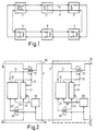
- stations 2 to 7 only the most important parts of the transmission path are specified, namely two changeover switches in the transmission path of each of the two lines 8 and 9 and a switch which can connect the two lines.
- the changeover switch for write line 8 is connected to a generator (not shown) for generating synchronization information for the temporal frame structure on write line 8, while read line 9 in station 7 is terminated connected is.
- the write line 8 in each station is connected to a transmitter for information to be transmitted and the read line 9 to a receiver for reading the information. If a station in a data channel within the frame structure sends out information via the write line 8, this information runs through all stations until it is coupled to the read line in station 7 and now again runs through all stations, including the station from which the information is sent has been. With known addressing and assignment methods can thus every station transmits information to every other station.
- station 2 can each send out a data word in one data channel on write line 8, and station 3 can send out one data word in another data channel.
- Both data words now pass through the stations 4, 5 and 6 on the write line 8 and are coupled in the station 7 to the read line 9, so that the transmitted data words again pass through the stations 6, 5 and 4 and finally in the stations 3 and 2 be received.
- Fig. 2 the two stations 2 and 3 assumed by way of example, between which there may of course be other stations, are shown as a block diagram with the most important elements, by means of which the simultaneous mutual transmission of information via the same data channel is possible. Both stations are constructed essentially the same, so that initially only the structure of station 2 is explained in more detail.
- Line 21 leads to an exclusive OR gate 22, the other input of which is coupled to the incoming write line 8a.
- the output signal of the exclusive OR gate 22 is linked by means of elements (not shown) to a clock signal which is generated by the processing unit 20 and is fed via the line 23, and the clocked output signal is sent via the outgoing write line 8b submitted.
- the information on line 21 is also fed to a memory 24, where it is also written with the clock signal on line 23.
- This memory 24 is expediently a so-called FIFO memory, which outputs the written information in the same order as when writing with a read clock on line 29 which is independent of the write clock.
- Line 25 leads to one input of a further exclusive OR gate 26, the other input of which is coupled to the incoming read line 9b, and the output signal of the exclusive OR gate 26 is fed to processing unit 20 via line 27.
- a clock regenerator 28 is also provided, which restores the data clock from the information on the read line 9b and outputs it as a clock signal on the line 29, which in addition to the memory 24 also leads to the processing unit 20.
- the station 3 is essentially constructed in the same way as the station 2, the processing unit 30 corresponding to the processing unit 20, the line 31 to the line 21 and the like.
- this data channel On the incoming write line 8a of station 2, this data channel is still empty, ie it contains, for example, all zeros. Their combination with the information to be sent on line 21 in the exclusive OR gate 22 now results
- This information now arrives in station 3 at one input of the exclusive OR gate 32 and is linked to the data on line 31: This is the information or the data word on the write line 8c in the relevant data channel, and this data word is coupled to the read line in the manner already described earlier and thus appears on the incoming read line 9c of the station 3, which has an exclusive input OR link 36 is connected. Whose other input receives via line 35 from memory 34 the information to be sent that appeared on line 31 earlier, so that the following results: The data word sent by station 2 is thus supplied to processing unit 30 via line 37.
- the data word arriving on the reading line 9c is now also unchanged on the incoming reading line 9b of the station 2 and is there the one input of the Exclusive-OR gate 26 supplied, the other input of the memory 24 via line 25 receives the data word previously sent out by station 2, so that the following results:
- the processing unit 20 thus receives the data word sent by the station 3 via the line 27.
- the exclusive OR element 22 only receives zeros via line 21, so that on write line 8b only zeros appear in station 3 in the data channel intended for transmission, and thus the information supplied on line 31 is transmitted unchanged to station 3 via outgoing write line 8c. In a corresponding manner, this information arrives via the incoming read line 9b in station 2 and is linked there in the exclusive OR gate 26 with only zeros from line 25, so that the information received on read line 9b remains unchanged via line 27 is fed to the processing unit 20. It can be seen from this that the exclusive OR elements 22 and 26 or 32 and 36 etc. do not impair normal data transmission, in which only one station transmits data words in a data channel.
Landscapes
- Engineering & Computer Science (AREA)
- Signal Processing (AREA)
- Computer Networks & Wireless Communication (AREA)
- Small-Scale Networks (AREA)
- Data Exchanges In Wide-Area Networks (AREA)
- Time-Division Multiplex Systems (AREA)
- Communication Control (AREA)
Applications Claiming Priority (2)
| Application Number | Priority Date | Filing Date | Title |
|---|---|---|---|
| DE3736466 | 1987-10-28 | ||
| DE19873736466 DE3736466A1 (de) | 1987-10-28 | 1987-10-28 | Verfahren zum uebertragen von informationen sowie anordnung zur durchfuehrung des verfahrens |
Publications (3)
| Publication Number | Publication Date |
|---|---|
| EP0314236A2 true EP0314236A2 (fr) | 1989-05-03 |
| EP0314236A3 EP0314236A3 (fr) | 1991-08-28 |
| EP0314236B1 EP0314236B1 (fr) | 1994-08-24 |
Family
ID=6339240
Family Applications (1)
| Application Number | Title | Priority Date | Filing Date |
|---|---|---|---|
| EP88202322A Expired - Lifetime EP0314236B1 (fr) | 1987-10-28 | 1988-10-18 | Procédé et dispositif de transmission d'informations |
Country Status (4)
| Country | Link |
|---|---|
| US (1) | US4932025A (fr) |
| EP (1) | EP0314236B1 (fr) |
| JP (1) | JP2758004B2 (fr) |
| DE (2) | DE3736466A1 (fr) |
Cited By (1)
| Publication number | Priority date | Publication date | Assignee | Title |
|---|---|---|---|---|
| WO1995030293A1 (fr) * | 1994-04-29 | 1995-11-09 | Philips Electronics N.V. | Procede et systeme de transmission de messages et station destinee a ce type de systeme |
Family Cites Families (6)
| Publication number | Priority date | Publication date | Assignee | Title |
|---|---|---|---|---|
| FR2357118A1 (fr) * | 1976-07-02 | 1978-01-27 | Thomson Csf | Dispositif antilocal pour transmission de signaux numeriques |
| JPS56169450A (en) * | 1980-05-30 | 1981-12-26 | Agency Of Ind Science & Technol | Double hair pin type network system |
| IT1157035B (it) * | 1982-06-09 | 1987-02-11 | Cselt Centro Studi Lab Telecom | Sistema di raccolta e commutazione a banda variabile per voci e dati |
| US4498168A (en) * | 1982-12-13 | 1985-02-05 | Trw Inc. | Communication network and method for its use |
| US4516236A (en) * | 1983-09-26 | 1985-05-07 | Northern Telecom Limited | Full-duplex transmission of bit streams serially and in bit-synchronism on a bus between two terminals. |
| DE3427891A1 (de) * | 1984-07-28 | 1986-01-30 | Philips Patentverwaltung Gmbh, 2000 Hamburg | Anordnung zur informationsuebertragung mit rekonfiguration |
-
1987
- 1987-10-28 DE DE19873736466 patent/DE3736466A1/de not_active Withdrawn
-
1988
- 1988-10-18 EP EP88202322A patent/EP0314236B1/fr not_active Expired - Lifetime
- 1988-10-18 DE DE3851199T patent/DE3851199D1/de not_active Expired - Fee Related
- 1988-10-26 US US07/263,099 patent/US4932025A/en not_active Expired - Lifetime
- 1988-10-28 JP JP63271137A patent/JP2758004B2/ja not_active Expired - Fee Related
Cited By (1)
| Publication number | Priority date | Publication date | Assignee | Title |
|---|---|---|---|---|
| WO1995030293A1 (fr) * | 1994-04-29 | 1995-11-09 | Philips Electronics N.V. | Procede et systeme de transmission de messages et station destinee a ce type de systeme |
Also Published As
| Publication number | Publication date |
|---|---|
| JP2758004B2 (ja) | 1998-05-25 |
| DE3851199D1 (de) | 1994-09-29 |
| DE3736466A1 (de) | 1989-05-11 |
| US4932025A (en) | 1990-06-05 |
| JPH01149551A (ja) | 1989-06-12 |
| EP0314236A3 (fr) | 1991-08-28 |
| EP0314236B1 (fr) | 1994-08-24 |
Similar Documents
| Publication | Publication Date | Title |
|---|---|---|
| DE2535573A1 (de) | Verfahren zur ueberpruefung der richtigen durchschaltung bei digitalen datenuebertragungssystemen, insbesondere digitalen telefonsystemen | |
| EP0035731A2 (fr) | Procédé et dispositif pour le transfert de signaux de données | |
| DE2758151A1 (de) | Einrichtung zum sortieren von datensaetzen | |
| DE3041556C2 (de) | Verfahren und Schaltungsanordnung zur Vermittlung von Daten zwischen Datenendgeräten | |
| DE2826450C3 (de) | Verfahren zum Steuern der Übertragung digitaler Signale und Anordnung zur Durchführung des Verfahrens bei einer digitalen Faksimileübertragungseinrichtung | |
| DE3729732C2 (fr) | ||
| EP0314236B1 (fr) | Procédé et dispositif de transmission d'informations | |
| DE68903986T2 (de) | Vermittlungssystem fuer leitungs- und/oder paketvermittelte nachrichtenuebertragungen. | |
| EP0840230B1 (fr) | Dispositif et méthode de sélection de mots d'adresse utilisant du décodage de démultiplexage | |
| EP0173274A2 (fr) | Méthode et montage pour la réalisation et la maintenance d'une liaison à division temporelle à large bande | |
| DE2824260A1 (de) | Datenuebertragungseinrichtung | |
| EP1054532B1 (fr) | Procédé de transmission de données | |
| EP0006986A1 (fr) | Système de transmission de données, procédé de mise en oeuvre du dit système, et circuit pour le dit système | |
| DE2660857C2 (de) | Mehrzweckzeitgeber für eine Schaltungsanordnung zur Übertragung von durch je eine Bitgruppe darstellbaren Zeichen zwischen einer Rechenanlage und zahlreichen Fernstationen | |
| DE4105468C2 (de) | Verfahren und Schaltungsanordnung zum Übertragen von asynchronen Datensignalen über eine 2-Draht-Übertragungsleitung | |
| DE69217764T2 (de) | Übertragungsvorrichtung mit Rundsendefunktion | |
| EP0349079A2 (fr) | Circuit pour la transmission d'information | |
| DE3328893A1 (de) | Schaltungsanordnung fuer fernmeldeanlagen, insbesondere fernsprechvermittlungsanlagen, mit datensicherung durch paritaetsbits | |
| DE3534581C2 (fr) | ||
| DE3412895C2 (fr) | ||
| DE3132199C2 (de) | Verfahren und Schaltungsanordnung zur Übertragung von Datensignalen im Zeitmultiplexverfahren | |
| DE3725299C1 (de) | Verfahren zum Umsetzen von Zeichen eines Textes | |
| EP0005489B1 (fr) | Méthode et circuit pour la transmission de données entre une station centrale et un parmi plusieurs postes de données dans un réseau de données synchrone à structure d'enveloppe | |
| DE4227042C2 (de) | Verfahren und Schaltungsanordnung zur Übertragung von Daten zwischen peripheren Anschlußgruppen eines Kommunikationssystems | |
| DE3042272C2 (de) | Zeitmultiplex-Datenübertragungseinrichtung für unterschiedliche Teilnehmer-Übertragungsgeschwindigkeiten |
Legal Events
| Date | Code | Title | Description |
|---|---|---|---|
| PUAI | Public reference made under article 153(3) epc to a published international application that has entered the european phase |
Free format text: ORIGINAL CODE: 0009012 |
|
| AK | Designated contracting states |
Kind code of ref document: A2 Designated state(s): DE FR GB SE |
|
| PUAL | Search report despatched |
Free format text: ORIGINAL CODE: 0009013 |
|
| AK | Designated contracting states |
Kind code of ref document: A3 Designated state(s): DE FR GB SE |
|
| 17P | Request for examination filed |
Effective date: 19920228 |
|
| 17Q | First examination report despatched |
Effective date: 19930302 |
|
| GRAA | (expected) grant |
Free format text: ORIGINAL CODE: 0009210 |
|
| AK | Designated contracting states |
Kind code of ref document: B1 Designated state(s): DE FR GB SE |
|
| REF | Corresponds to: |
Ref document number: 3851199 Country of ref document: DE Date of ref document: 19940929 |
|
| GBT | Gb: translation of ep patent filed (gb section 77(6)(a)/1977) |
Effective date: 19941110 |
|
| ET | Fr: translation filed | ||
| EAL | Se: european patent in force in sweden |
Ref document number: 88202322.9 |
|
| REG | Reference to a national code |
Ref country code: FR Ref legal event code: CD |
|
| PLBE | No opposition filed within time limit |
Free format text: ORIGINAL CODE: 0009261 |
|
| STAA | Information on the status of an ep patent application or granted ep patent |
Free format text: STATUS: NO OPPOSITION FILED WITHIN TIME LIMIT |
|
| 26N | No opposition filed | ||
| REG | Reference to a national code |
Ref country code: FR Ref legal event code: CD |
|
| REG | Reference to a national code |
Ref country code: GB Ref legal event code: 732E |
|
| REG | Reference to a national code |
Ref country code: FR Ref legal event code: TP |
|
| REG | Reference to a national code |
Ref country code: FR Ref legal event code: CD |
|
| REG | Reference to a national code |
Ref country code: GB Ref legal event code: IF02 |
|
| PGFP | Annual fee paid to national office [announced via postgrant information from national office to epo] |
Ref country code: DE Payment date: 20020924 Year of fee payment: 15 |
|
| PGFP | Annual fee paid to national office [announced via postgrant information from national office to epo] |
Ref country code: GB Payment date: 20020927 Year of fee payment: 15 |
|
| PGFP | Annual fee paid to national office [announced via postgrant information from national office to epo] |
Ref country code: FR Payment date: 20021015 Year of fee payment: 15 |
|
| PGFP | Annual fee paid to national office [announced via postgrant information from national office to epo] |
Ref country code: SE Payment date: 20031007 Year of fee payment: 16 |
|
| PG25 | Lapsed in a contracting state [announced via postgrant information from national office to epo] |
Ref country code: GB Free format text: LAPSE BECAUSE OF NON-PAYMENT OF DUE FEES Effective date: 20031018 |
|
| PG25 | Lapsed in a contracting state [announced via postgrant information from national office to epo] |
Ref country code: DE Free format text: LAPSE BECAUSE OF NON-PAYMENT OF DUE FEES Effective date: 20040501 |
|
| GBPC | Gb: european patent ceased through non-payment of renewal fee |
Effective date: 20031018 |
|
| PG25 | Lapsed in a contracting state [announced via postgrant information from national office to epo] |
Ref country code: FR Free format text: LAPSE BECAUSE OF NON-PAYMENT OF DUE FEES Effective date: 20040630 |
|
| REG | Reference to a national code |
Ref country code: FR Ref legal event code: ST |
|
| PG25 | Lapsed in a contracting state [announced via postgrant information from national office to epo] |
Ref country code: SE Free format text: LAPSE BECAUSE OF NON-PAYMENT OF DUE FEES Effective date: 20041019 |
|
| EUG | Se: european patent has lapsed |