EP0314258A2 - Sphincter hydraulique à commande manuelle - Google Patents
Sphincter hydraulique à commande manuelle Download PDFInfo
- Publication number
- EP0314258A2 EP0314258A2 EP88202700A EP88202700A EP0314258A2 EP 0314258 A2 EP0314258 A2 EP 0314258A2 EP 88202700 A EP88202700 A EP 88202700A EP 88202700 A EP88202700 A EP 88202700A EP 0314258 A2 EP0314258 A2 EP 0314258A2
- Authority
- EP
- European Patent Office
- Prior art keywords
- sphincter
- pressure
- fluid
- actuation
- chamber
- Prior art date
- Legal status (The legal status is an assumption and is not a legal conclusion. Google has not performed a legal analysis and makes no representation as to the accuracy of the status listed.)
- Withdrawn
Links
Images


Classifications
-
- A—HUMAN NECESSITIES
- A61—MEDICAL OR VETERINARY SCIENCE; HYGIENE
- A61F—FILTERS IMPLANTABLE INTO BLOOD VESSELS; PROSTHESES; DEVICES PROVIDING PATENCY TO, OR PREVENTING COLLAPSING OF, TUBULAR STRUCTURES OF THE BODY, e.g. STENTS; ORTHOPAEDIC, NURSING OR CONTRACEPTIVE DEVICES; FOMENTATION; TREATMENT OR PROTECTION OF EYES OR EARS; BANDAGES, DRESSINGS OR ABSORBENT PADS; FIRST-AID KITS
- A61F2/00—Filters implantable into blood vessels; Prostheses, i.e. artificial substitutes or replacements for parts of the body; Appliances for connecting them with the body; Devices providing patency to, or preventing collapsing of, tubular structures of the body, e.g. stents
- A61F2/0004—Closure means for urethra or rectum, i.e. anti-incontinence devices or support slings against pelvic prolapse
- A61F2/0031—Closure means for urethra or rectum, i.e. anti-incontinence devices or support slings against pelvic prolapse for constricting the lumen; Support slings for the urethra
- A61F2/0036—Closure means for urethra or rectum, i.e. anti-incontinence devices or support slings against pelvic prolapse for constricting the lumen; Support slings for the urethra implantable
- A61F2/004—Closure means for urethra or rectum, i.e. anti-incontinence devices or support slings against pelvic prolapse for constricting the lumen; Support slings for the urethra implantable inflatable
-
- A—HUMAN NECESSITIES
- A61—MEDICAL OR VETERINARY SCIENCE; HYGIENE
- A61F—FILTERS IMPLANTABLE INTO BLOOD VESSELS; PROSTHESES; DEVICES PROVIDING PATENCY TO, OR PREVENTING COLLAPSING OF, TUBULAR STRUCTURES OF THE BODY, e.g. STENTS; ORTHOPAEDIC, NURSING OR CONTRACEPTIVE DEVICES; FOMENTATION; TREATMENT OR PROTECTION OF EYES OR EARS; BANDAGES, DRESSINGS OR ABSORBENT PADS; FIRST-AID KITS
- A61F2/00—Filters implantable into blood vessels; Prostheses, i.e. artificial substitutes or replacements for parts of the body; Appliances for connecting them with the body; Devices providing patency to, or preventing collapsing of, tubular structures of the body, e.g. stents
- A61F2/0004—Closure means for urethra or rectum, i.e. anti-incontinence devices or support slings against pelvic prolapse
-
- A—HUMAN NECESSITIES
- A61—MEDICAL OR VETERINARY SCIENCE; HYGIENE
- A61F—FILTERS IMPLANTABLE INTO BLOOD VESSELS; PROSTHESES; DEVICES PROVIDING PATENCY TO, OR PREVENTING COLLAPSING OF, TUBULAR STRUCTURES OF THE BODY, e.g. STENTS; ORTHOPAEDIC, NURSING OR CONTRACEPTIVE DEVICES; FOMENTATION; TREATMENT OR PROTECTION OF EYES OR EARS; BANDAGES, DRESSINGS OR ABSORBENT PADS; FIRST-AID KITS
- A61F2/00—Filters implantable into blood vessels; Prostheses, i.e. artificial substitutes or replacements for parts of the body; Appliances for connecting them with the body; Devices providing patency to, or preventing collapsing of, tubular structures of the body, e.g. stents
- A61F2/50—Prostheses not implantable in the body
-
- A—HUMAN NECESSITIES
- A61—MEDICAL OR VETERINARY SCIENCE; HYGIENE
- A61M—DEVICES FOR INTRODUCING MEDIA INTO, OR ONTO, THE BODY; DEVICES FOR TRANSDUCING BODY MEDIA OR FOR TAKING MEDIA FROM THE BODY; DEVICES FOR PRODUCING OR ENDING SLEEP OR STUPOR
- A61M25/00—Catheters; Hollow probes
- A61M25/01—Introducing, guiding, advancing, emplacing or holding catheters
-
- A—HUMAN NECESSITIES
- A61—MEDICAL OR VETERINARY SCIENCE; HYGIENE
- A61M—DEVICES FOR INTRODUCING MEDIA INTO, OR ONTO, THE BODY; DEVICES FOR TRANSDUCING BODY MEDIA OR FOR TAKING MEDIA FROM THE BODY; DEVICES FOR PRODUCING OR ENDING SLEEP OR STUPOR
- A61M39/00—Tubes, tube connectors, tube couplings, valves, access sites or the like, specially adapted for medical use
- A61M39/02—Access sites
- A61M39/0208—Subcutaneous access sites for injecting or removing fluids
- A61M2039/0211—Subcutaneous access sites for injecting or removing fluids with multiple chambers in a single site
- A61M2039/0214—Subcutaneous access sites for injecting or removing fluids with multiple chambers in a single site some or all chambers sharing a single septum
- A61M2039/0217—Subcutaneous access sites for injecting or removing fluids with multiple chambers in a single site some or all chambers sharing a single septum at least some chambers being stacked separated by another septum
-
- A—HUMAN NECESSITIES
- A61—MEDICAL OR VETERINARY SCIENCE; HYGIENE
- A61M—DEVICES FOR INTRODUCING MEDIA INTO, OR ONTO, THE BODY; DEVICES FOR TRANSDUCING BODY MEDIA OR FOR TAKING MEDIA FROM THE BODY; DEVICES FOR PRODUCING OR ENDING SLEEP OR STUPOR
- A61M39/00—Tubes, tube connectors, tube couplings, valves, access sites or the like, specially adapted for medical use
- A61M39/02—Access sites
- A61M39/0208—Subcutaneous access sites for injecting or removing fluids
-
- Y—GENERAL TAGGING OF NEW TECHNOLOGICAL DEVELOPMENTS; GENERAL TAGGING OF CROSS-SECTIONAL TECHNOLOGIES SPANNING OVER SEVERAL SECTIONS OF THE IPC; TECHNICAL SUBJECTS COVERED BY FORMER USPC CROSS-REFERENCE ART COLLECTIONS [XRACs] AND DIGESTS
- Y10—TECHNICAL SUBJECTS COVERED BY FORMER USPC
- Y10S—TECHNICAL SUBJECTS COVERED BY FORMER USPC CROSS-REFERENCE ART COLLECTIONS [XRACs] AND DIGESTS
- Y10S128/00—Surgery
- Y10S128/25—Artificial sphincters and devices for controlling urinary incontinence
Definitions
- the invention relates to an artificial sphincter for maintaining continence in those patients unable to control or stop inadvertent urinary flow. More particularly, the invention relates to a hydraulic sphincter (MAHS) which: automatically causes sphincter pressure to increase or decrease with bladder pressure and/or abdominal pressure; is manually actuated by the patient when he or she desires to urinate; and, allows sphincter fluid pressure to be measured and adjusted after implantation without necessitating a surgical procedure.
- MAHS hydraulic sphincter
- Urinary incontinence is a ubiquitous disorder which represents more than a personal inconvenience and social problem. For many, particularly those individuals suffering spinal injury, incontinence can cause life threatening complications. In the United States alone, it is estimated that 100,000 persons of all ages, many of them young veterans, have sustained spinal cord injuries rendering them incontinent. Pyelonephritis, a kidney infection produced by bacterial spread from the lower urinary tract, has been the leading cause of death among paralyzed World War II and Korean war veterans. Neurologic dysfunction of the urinary sphincter can also occur because of multiple sclerosis, stroke, cerebrovascular disease, Parkinson disease and diabetes. Approximately 20% of the population over 65 suffer from incontinence.
- incontinence largely the result of changes in bladder geometry following child birth. Many men experience incontinence after prostate surgery. Finally, incontinence can result from meningomyelocoele, amyotrophic lateral sclerosis, spinal cord or brain tumor, head injury, herniated disc, syringomyelia and tabes dorsalis.
- U.S. 3,815,576 issued to Donald R. Balaban teaches the use of a fluid filled flexible container implanted in the patient which is squeezed manually to actuate a piston-cylinder in a U-shaped clamp.
- U.S. patent 4,056,095 issued to Pierre Rey et al and U.S. patent 4,178,915 issued to Gerhard Szinicz et al teach the use of a fluid filled artificial sphincter which is actuated by pressing on the subcutaneously implanted membrane.
- These references share the disadvantage of having no control over the pressure exerted by the artificial sphincter on the urethra once the apparatus is implanted.
- patent 3,744,063 issued to McWhorter et al teaches controlling the flow of a fluid into the sphincter so that pressure applied to the urethra is graduated and controlled.
- variable pressure is controlled manually by applying digital pressure to an implanted pump chamber.
- the patient increases the sphincter pressure after dripping incontinence has occurred and been detected.
- the patient would not be able to respond to rapid changes in bladder pressure caused by bladder spasms, voluntarily or involuntary tensing of the diaphragm or abdominal wall, or increased intra-abdominal pressure due to walking, sitting, coughing or laughing.
- the present inventor recognized the above-mentioned problems and has invented a manually actuated hydraulic sphincter which automatically increases sphincter pressure with increasing bladder pressure.
- An implanted hydraulic control unit automatically adjusts sphincter fluid pressure so that the fluid filled artificial sphincter exerts just enough pressure on the urethra to prevent incontinence.
- the present invention has the advantage that the artificial sphincter can be implanted and remain void of fluid until the urethra has healed and swelling been reduced.
- the invention allows fluid to be added, after implantation, by inserting a hypodermic syringe through an appropriate septum into the invented device and adding fluid until an appropriate sphincter pressure is obtained.
- the present invention can, therefore, be safely implanted without the need for the repeat operation required in the prior art.
- pressure exerted by the artificial sphincter can be measured and controlled at any time after implantation.
- a low sphincter pressure can be initially set (e.g., 10 cm of H2O above bladder pressure) which minimizes the possibility of urethral necrosis. If this pressure is shown to be insufficient to maintain continence, it can be increased using a simple hypodermic syringe that adds artificial sphincter fluid without requiring surgical intervention. If the minimum pressure required to maintain continence changes with time in a particular patient, it can be modified by adding fluid (to increase sphincter pressure) or removing fluid (to decrease sphincter pressure) by means of a hypodermic syringe. Any similar adjustment to prior art devices would have required an additional surgical operation.
- the invented hydraulic control unit automatically maintains sphincter pressure at a set differential above bladder pressure and/or abdominal pressure.
- This pressure differential is set at the minimal level necessary to provide continence, thereby assuring little or no urethral tissue damage.
- the cystometrogram of a normal bladder shows a modest rise in pressure with the first 50 cc of fluid followed by a plateau as the fluid volume increased in the range of 100 to 400 cc.
- the bladder pressure increases rapidly.
- the pressure exerted by the artificial sphincter of the present invention will correspondingly increase while at the same time retaining a fixed differential value above that bladder pressure.
- Bladder pressure or abdominal pressure also can increase rapidly because of bladder spasm, voluntary or involuntary tensing of the diaphragm or abdominal wall, or increased intra-abdominal pressure due to walking, sitting, coughing or laughing. If for example the patient's bladder or diaphragm spasms, bladder pressure will increase rapidly. To prevent dribbling or stress incontinence the pressure exerted by the artificial sphincter on the urethra may be required to exceed diastolic pressure at least for that short period of time when the bladder pressure exceeds diastolic pressure.
- Prior art devices to prevent such dribbling incontinence, would have to constantly maintain sphincter pressure above diastolic pressure thereby causing necrosis of urethral tissue which is permanently damaging.
- the invented apparatus will automatically increase sphincter fluid pressure only for the length of the spasm, thereby causing no threat of tissue necrosis.
- the invented apparatus therefore can provide continence during bladder pressure peaks without causing necrosis of the urethral tissue.
- the pressure sensing bulb can be implanted in the wall of the bladder, thereby directly sensing bladder pressure, or it can be placed in the abdomen just below the bladder. When at the latter location, the pressure sensed would be that of abdominal pressure plus to some extent a pressure that is dependent on the extent to which the bladder is filled. Placement in the abdominal area may be advantageous if bladder wall surgery is difficult or contraindicated for a particular patient.
- the present invention includes a subcutaneously implanted control unit which is hydraulically connected to: an artificial sphincter which surrounds a portion of the urethra; and, a bladder pressure sensing bulb.
- the control unit contains the following three fluid filled chambers: an actuation chamber, a sphincter fluid chamber, and a pressure reference chamber.
- the sphincter fluid chamber is hydraulically coupled to the artificial urethral sphincter such that pressure exerted by the sphincter varies according to the fluid pressure in the sphincter fluid chamber.
- the pressure reference chamber is hydraulically coupled to the bladder pressure bulb and fluid pressure in the chamber increases as the bladder pressure bulb is compressed by increased bladder or intra-abdominal pressure.
- a common wall membrane between the sphincter fluid chamber and the pressure reference chamber acts as a pressure differential means automatically maintaining the sphincter fluid at a set pressure differential above the sensed bladder pressure.
- An actuation means included in the control unit contains an actuation chamber, an actuation diaphragm and at least one actuation bellows.
- the actuation diaphragm is positioned on the outer face of the control unit so that it can be pressed by manually applying pressure to the abdominal skin layer immediately above the implant. When the actuation diaphragm is pressed, displaced fluid elongates the actuation bellows. The elongated actuation bellows press against the sphincter fluid chamber's common wall membrane, thereby increasing sphincter fluid chamber volume and lowering the sphincter fluid pressure. In operation, manual pressure applied to the actuation diaphragm reduces sphincter pressure, allowing the patient to freely urinate.
- the Manually Actuated Hydraulic Sphincter also contains an invented means for adjusting the fluid pressure level in the hydraulic control unit after implantation.
- the apparatus includes three septums - an outer septum comprising part of the actuation diaphragm; and, two inner septums each comprising part of the wall separating the two inner chambers.
- a non-coring hypodermic needle is inserted through the septums into the desired chamber.
- a side hole in the hypodermic needle allows the physician access to the fluid so he can measure its pressure or add or remove fluid as desired.
- This feature allows the physician to replace any lost fluid or to reset the system's parameters, allowing the physician to: (1) adjust the sensitivity of the actuation means to external pressure, (2) adjust the differential pressure exerted by the artificial sphincter; or, (3) adjust the pressure level in the pressure reference chamber so it is reasonably close to actual bladder pressure.
- a first novel feature of the invention is a manually actuated hydraulic sphincter which can prevent incontinence, over a wide range of bladder and intra-abdominal pressure, without causing necrosis of the urethral tissue.
- a second novel feature of the invention is the use of a control unit which automatically increases sphincter pressure in relation to increases in bladder pressure and/or abdominal pressure.
- a third novel feature of the invention is the use of a control unit which has a bladder pressure sensing bulb, implanted in association with the bladder, to sense bladder pressure and/or abdominal pressure.
- a fourth novel feature is the use of a control unit which contains a means for adjusting the fluid pressure levels after the unit is implanted.
- a fifth novel feature is the use of a manual actuation means which can be adjusted for sensitivity to external pressure, after it is implanted.
- a sixth novel feature is the use of a manually actuated hydraulic sphincter which can be adjusted after implantation to set or reset the sphincter pressure.
- a seventh novel feature is the use of a manually actuated hydraulic sphincter which can be adjusted to meet the patient's physiological parameters at any time after implantation.
- An eighth novel feature is the ability to measure actuation, sensor and reference pressure levels after implantation.
- a ninth novel feature is that the bladder pressure sensing bulb is expanded each time MAHS is actuated for voiding thus preventing the buildup of body tissue encapsulation around the sensing bulb.
- the invented apparatus for manually actuating an artificial hydraulic sphincter is illustrated in Figure 1.
- the apparatus is generally composed of: an implantable hydraulic control unit 10; an artificial sphincter 12 which is hydraulically coupled by pressure line 14 to control unit 10; and, a bladder pressure sensing bulb 16 implanted in association with the bladder which is hydraulically coupled by pressure line 18 to control unit 10.
- the control unit is contained in a disk shape casing which is implanted subcutaneously, just beneath the skin, in the patient's abdomen.
- FIG. 2 shows a more detailed view of the invented apparatus.
- the artificial sphincter 12 is shown surrounding a portion of the urethra 20.
- the artificial sphincter 12 and associated pressure line 14 are filled with an incompressible sphincter fluid 22.
- An actuation diaphragm 24 is mounted on the surface of control unit 10 that is just under the skin. When the control unit 10 is implanted subcutaneously, the actuation diaphragm 24 can be pressed by manually applying pressure to the skin just above the implant.
- a bladder pressure sensing bulb 16 is implanted in the wall 32 of the bladder 26 and senses bladder fluid pressure by compressing slightly as bladder pressure increases.
- the bladder pressure sensing bulb 16′ can be placed anywhere in the abdomen specifically in the abdomen just below the bladder. When at this location the bulb can sense abdominal pressure plus to some extent a pressure which is dependent on bladder volume.
- the bladder pressure sensing bulb 16 (alternatively, bladder pressure sensing bulb 16′) is filled with an incompressible reference pressure fluid 28, and is hydraulically linked by line 18 (alternatively, line 18′) to control unit 10.
- Control unit 10 in turn is adjusted so that the sphincter fluid pressure is set at a minimum pressure differential necessary to avoid tissue damage while maintaining continence.
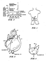
- the contractile responses of the bladder in the presence of increased urinary volume are displayed in the cystometrogram, illustrated in Figure 3.
- the cystometrogram of a normal bladder shows a modest rise in pressure with the first 50 cc of fluid (segment A) followed by a plateau as the fluid volume increases from 100 to 400 cc (segment B).
- the bladder pressure increases rapidly (segment D).
- the invented hydraulic control unit MAHS) automatically tends to maintain sphincter pressure at a differential value above bladder pressure as is shown by the dotted line in Figure 3.
- Figures 4 and 5 illustrate two possible methods of surgically attaching the pressure sensing bulb 16 to the bladder 26.
- Figure 4 shows the bladder pressure sensing bulb 16 plicated into the wall of the bladder 26. Surgical sutures at the opening of the plication 30 hold the bladder pressure bulb in place.
- Figure 5 shows an alternative placement of the bladder pressure bulb near the interior of the detrusor muscle 32. The detrusor muscle 32 is dissected by known medical techniques and a flat bladder pressure bulb is placed therein. In operation, as the bladder fluid pressure increases the surgically implanted bladder pressure sensing bulb 16 will be compressed and fluid pressure in the bulb will increase.
- the bladder pressure sensing bulb 16 can be made from medical grade silicon rubber or bromo-butyl rubber and is of a wall-like construction.
- the bulb 16 can have a limited fluid volume so that if bladder pressure exceeds a predetermined limit all the fluid is driven out of the bulb 16 and the sphincter pressure will then not continue to increase with increasing bladder pressure. Thus, if the patient becomes unconscious and bladder pressure exceeds, let us say, 100 cm of the H2O, then urine will start to flow out through the urethra.
- Figure 6 shows three views of the artificial urethral sphincter 12.
- Figure 6A shows the urethra 20, in a swollen condition which occurs soon after surgery and lasts for several days.
- the urethra 20 is swollen, the lumen 21, through which the urine must pass, remains open because the sphincter bulb 17, is unfilled at this time.
- the bulb 17, can be filled with sphincter fluid as shown in Figure 6B causing the urethra 20, to be compressed and the lumen 21, to be closed thus providing continence.
- Figure 6C shows the bulb 17, with fluid decreased to the point so that the lumen 21, is opened and the patient can then void. Control of the fluid level in the bulb 17, is accomplished by means of the control unit 10, which is shown in Figures 1, 2, 8 and 9.
- Figure 7 shows some construction details of the sphincter bulb 17.
- Figure 7A is a plan view of the sphincter bulb 17, which is connected by line 14 to the control unit 10 (not shown in Figure 7).
- the sphincter bulb 17 might be approximately 2 cm long and 1 cm across and would be fabricated from medical grade silicon rubber or bromo-butyl rubber.
- Figure 7B shows a cross-section of the bulb 17 at low fluid level (for voiding), and the expanded bulb 17′ illustrates a cross-section at a fluid level high enough to maintain continence.
- Figure 8 is a cross-section of the manually actuated hydraulic control unit 10.
- Actuation chamber 34 is mounted inside the outer casing 36 of control unit 10.
- the upper wall of the actuation chamber 34 contains a flexible actuation diaphragm 24 which is positioned on the front surface of the outer casing 36 that is just beneath the patient's skin.
- the diaphragm 24 might be fabricated from titanium metal and might be 1 to 10 mils thick and have a corrugated pattern as shown in Figure 8.
- the diaphragm 24 might otherwise be fabricated from an elastometer such as medical grade silicone or bromo-butyl rubber.
- the actuation chamber's lower wall 38 contains at least one flexible actuation bellows 40.
- actuation bellows are equally spaced along the inner circumference of the actuation chamber's lower wall and are connected at their lower extremity to torroidal actuation ring 41 (only two of the actuation bellows are shown in the cross-sectional view of Figure 8).
- the bellows might be fabricated from thin metal or an elastometer.
- the actuation chamber 34 is filled with an incompressible actuation fluid 42.
- the actuation chamber 34, flexible actuation diaphragm 24 and actuation bellows 40 act as a means for actuating the artificial sphincter. Pressing on the flexible actuation diaphragm 24, causes the incompressible actuation fluid 42 to be displaced and to elongate the actuation bellows 40.
- Sphincter fluid chamber 44 is mounted inside outer casing 36 adjacent to the actuation chamber 34 and is hydraulically connected by pressure line 14 to the artificial urethral sphincter 12.
- the actuation chamber's lower wall 38 also forms the upper wall of the sphincter fluid chamber 44.
- the sphincter fluid chamber's lower wall 46 contains an elastic diaphragm, that is positioned such that as actuation bellows 40 become elongated they press against the elastic diaphragm 46.
- the sphincter fluid chamber 44 is filled with an incompressible sphincter fluid 22.
- the spring force exerted by elastic diaphragm 46 tends to keep the sphincter fluid 22 in the chamber 44, in the pressure line 14 and in the sphincter bulb 17 at a predetermined minimum differential pressure above that pressure of the pressure reference chamber 48.
- the actuation bellows 40 when they are elongated they press against the elastic diaphragm 46 increasing the volume of the sphincter fluid chamber 44 and decreasing the pressure of the sphincter fluid 22, thereby allowing the urethral sphincter 12 to decrease in volume and pressure and therefore the patient can urinate.
- a spacing 47 separates the bottom of torroidal actuation ring 41 from elastic diaphragm 46, preventing inadvertent urination due to spurious pressure on the actuation diaphragm 24.
- Pressure reference chamber 48 is located in the lower section of rigid outer casing 36 and is hydraulically connected by pressure line 18 to bladder pressure sensing bulb 16 (not shown in Fig. 8). Pressure reference chamber 48 is located below the sphincter fluid chamber 44, such that elastic diaphragm 46 is a common wall separating the pressure reference chamber 48 and sphincter fluid chamber 44.
- the pressure reference chamber 48, pressure line 18 and bladder pressure sensing bulb 16 are all filled with an incompressible reference pressure fluid 28. An increase in fluid pressure in the pressure reference chamber 48, will result when the bladder pressure sensing bulb 16 (not shown in Figure 8) is tending toward compression by increased abdominal pressure and increased bladder volume or pressure.
- An increase in fluid pressure in the reference pressure chamber 48 will cause elastic diaphragm 46 to flex thereby decreasing the volume of the sphincter fluid chamber 44 and increasing the sphincter fluid pressure.
- This interaction between the pressure reference chamber 48 and the sphincter fluid chamber 44 provides a means for obtaining continence while providing minimal applied pressure to the urethra for all conditions of the bladder.
- This pressure differential means maintains a set (and nearly constant) pressure differential between the pressure exerted by the artificial sphincter 12 and pressure sensed by the bladder pressure sensing bulb 16.
- the spring force of elastic diaphragm 46 is a means to maintain a minimal differential sphincter fluid pressure so as to provide continence without urethral necrosis.
- bladder pressure sensing bulb 16 will tend to compress causing an increase in reference fluid pressure which causes elastic diaphragm 46 to flex, and correspondingly increases sphincter fluid pressure above the set minimal value.
- This pressure differential means assures that sphincter fluid pressure is greater than the sensed bladder pressure or sensed abdominal pressure. Pressure exerted by the artificial sphincter on the urethra will track with bladder pressure and/or abdominal pressure.
- the differential sphincter fluid pressure might be 20 to 60 cms of water. The absolute value of the sphincter fluid pressure will increase as the bladder fills or as abdominal pressure increases.
- the invented apparatus automatically adjusts sphincter fluid pressure so that the artificial sphincter exerts the minimum pressure necessary to maintain continence without causing urethral necrosis.
- Sphincter fluid pressure is automatically adjusted to compensate for increases in bladder pressure due to bladder fill, bladder spasm, voluntarily or involuntary tensing of the diaphragm or abdominal wall, or increased intra-abdominal pressure due to walking, sitting, coughing or laughing.
- the patient places his fingers on the skin over the center of the implanted apparatus and presses vigorously with his fingers on the actuation diaphragm 24.
- MAHS MAHS
- the pressure in the pressure sensing bulb 16 is increased thus increasing its volume. This size change is intended to prevent encapsulation of the bulb 16 by the growth of body tissue around the bulb 16. Thus, the bulb 16 will remain functional, i.e., continue to accurately sense pressure.
- Figures 9 and 10 show an invented means for measuring and adjusting fluid pressure in the control unit 10 while it is implanted.
- An outer septum 50 is mounted in a rigid ring 52 which is itself mounted in the center portion of the actuation diaphragm 24.
- Outer septum 50 is made from self-sealing material so that a non-coring type hypodermic needle can penetrate the septum and be withdrawn without causing the seal to leak.
- the septum could, for example, be made from medical grade silicon or bromo-butyl rubber.
- Two inner septums 54, 56 are mounted on a rigid center support ring 58. The first inner septum 54 becomes part of the rigid wall 38 separating the actuation chamber 34 from the sphincter fluid chamber 44.
- the second inner septum 56 provides a section of the wall separating the sphincter fluid chamber 44 and the pressure reference chamber 48.
- Elastic membrane 46 is attached between the rigid center support ring 58 and the outer casing 36 and provides the remainder of the common wall separating these two chambers.
- the center support ring 58 contains fluid passageways 60 and 61 which allow respectively sphincter fluid and pressure reference fluid to freely flow within their respective chambers.
- FIG 10 is an enlarged cross-section view showing three hypodermic needles passing through each of the three septums.
- the hypodermic needles are used in conjunction with the septums as a means to: (1) replenish any of the three fluids, (2) adjust the pressure and fluid volume in each of the three fluid chambers, and (3) provide a means for measurement of the pressure in each of the three fluid chambers.
- Hypodermic needles 62, 64, 66 are of the non-coring type with side holds for adding or withdrawing fluid and making pressure measurements. The position of the side hole relative to the end of the hypodermic needle determines which of the three fluid chambers can be accessed by that specific hypodermic needle. Any one of the three hypodermic needles could be connected by tubing to a pressure gauge 68 and a syringe 70 thereby allowing fluid pressure in a specific chamber to be measured. This allows the physician to adjust fluid pressure by adding or removing fluid.
- the center hypodermic 64 can be inserted through all three septums with its side hole entering the sphincter fluid chamber 44.
- the pressure gauge will read the sphincter fluid pressure and the physician would then know the pressure exerted by the artificial sphincter on the urethra. If a change in sphincter fluid pressure is desired, fluid can be added to or removed from sphincter fluid chamber 44. When fluid is added, the pressure exerted by the artificial sphincter will be increased; when fluid is removed the pressure exerted by the artificial sphincter is decreased.
- Hypodermic needle 62 shown in Figure 10 is designed to measure the fluid pressure in pressure reference chamber 48.
- the urologist can measure bladder pressure directly using a urethral catheter and compare that value with the pressure measured in pressure reference chamber 48.
- fluid can be added or removed as necessary to adjust pressure in the reference chamber to be closely equal to bladder pressure and/or abdominal pressure.
- hypodermic needle 66 shown in Figure 10 is designed to access fluid in actuation chamber 34. If the patient is inadvertently urinating because of spurious pressure on actuation diaphragm 24, actuation fluid could be removed, thereby, increasing the separation 47 of the actuation bellows 40 from the elastic diaphragm 46, which would tend to decrease the possibility of inadvertent urination.
- the use of two or three of such needles might be utilized to determine the interactions of the various fluids within the hydraulic control unit.
- one or more needles might be used in conjunction with a urinary catheter connected to a pressure gauge that measures bladder pressure directly.
- the invented means for measuring and varying fluid pressure in the hydraulic control unit could have application in a simplified two-chamber hydraulic control unit.
- the two chamber design would have an actuation chamber and a sphincter fluid chamber and could be used to control an artificial urinary sphincter when sensing bladder pressure is not desired.
- the two chamber design could be used in an artificial anal sphincter.
- all metal parts used in the hydraulic control unit 10 could be fabricated from pure titanium and the outer titanium casing 36, would have an upper half 36′ and a lower half 36 ⁇ allowing for simpler fabrication.
- the septums as has been mentioned previously, could be made from medical grade silicon or bromo-butyl rubber. All three fluids could be normal saline (5% NaCl in H2O) or silicon fluid or any other fluid that would not cause harm to the patient if inadvertently released.
Landscapes
- Health & Medical Sciences (AREA)
- Life Sciences & Earth Sciences (AREA)
- General Health & Medical Sciences (AREA)
- Engineering & Computer Science (AREA)
- Veterinary Medicine (AREA)
- Biomedical Technology (AREA)
- Heart & Thoracic Surgery (AREA)
- Public Health (AREA)
- Animal Behavior & Ethology (AREA)
- Urology & Nephrology (AREA)
- Transplantation (AREA)
- Cardiology (AREA)
- Oral & Maxillofacial Surgery (AREA)
- Vascular Medicine (AREA)
- Hematology (AREA)
- Anesthesiology (AREA)
- Pulmonology (AREA)
- Biophysics (AREA)
- Prostheses (AREA)
- Orthopedics, Nursing, And Contraception (AREA)
Applications Claiming Priority (2)
| Application Number | Priority Date | Filing Date | Title |
|---|---|---|---|
| US06/421,441 US4571749A (en) | 1982-09-21 | 1982-09-21 | Manually actuated hydraulic sphincter |
| US421441 | 1995-04-20 |
Related Parent Applications (3)
| Application Number | Title | Priority Date | Filing Date |
|---|---|---|---|
| EP83903265A Division-Into EP0119265B1 (fr) | 1982-09-21 | 1983-09-21 | Sphincter hydraulique fonctionnant manuellement |
| EP83903265A Division EP0119265B1 (fr) | 1982-09-21 | 1983-09-21 | Sphincter hydraulique fonctionnant manuellement |
| EP83903265.3 Division | 1983-09-21 |
Publications (2)
| Publication Number | Publication Date |
|---|---|
| EP0314258A2 true EP0314258A2 (fr) | 1989-05-03 |
| EP0314258A3 EP0314258A3 (fr) | 1989-10-04 |
Family
ID=23670527
Family Applications (2)
| Application Number | Title | Priority Date | Filing Date |
|---|---|---|---|
| EP83903265A Expired EP0119265B1 (fr) | 1982-09-21 | 1983-09-21 | Sphincter hydraulique fonctionnant manuellement |
| EP88202700A Withdrawn EP0314258A3 (fr) | 1982-09-21 | 1983-09-21 | Sphincter hydraulique à commande manuelle |
Family Applications Before (1)
| Application Number | Title | Priority Date | Filing Date |
|---|---|---|---|
| EP83903265A Expired EP0119265B1 (fr) | 1982-09-21 | 1983-09-21 | Sphincter hydraulique fonctionnant manuellement |
Country Status (10)
| Country | Link |
|---|---|
| US (1) | US4571749A (fr) |
| EP (2) | EP0119265B1 (fr) |
| JP (1) | JPS59501779A (fr) |
| CA (1) | CA1236251A (fr) |
| DE (1) | DE3390208T1 (fr) |
| ES (1) | ES535151A0 (fr) |
| GB (2) | GB2137505B (fr) |
| IT (1) | IT1166961B (fr) |
| SE (1) | SE456317B (fr) |
| WO (1) | WO1984001098A1 (fr) |
Cited By (4)
| Publication number | Priority date | Publication date | Assignee | Title |
|---|---|---|---|---|
| DE10156558A1 (de) * | 2001-11-20 | 2003-05-28 | Helmut Wassermann | Verschlusssystem und ein Verfahren hierzu |
| EP1584303A1 (fr) * | 2000-02-14 | 2005-10-12 | Potencia Medical AG | Appareil hydraulique destiné au traitement de l'incontinence anale |
| US7217237B2 (en) | 2001-11-20 | 2007-05-15 | Dieter Jocham | Closing system and electronic control method |
| CN105431184A (zh) * | 2013-06-27 | 2016-03-23 | 迷你泵有限责任公司 | 用于可植入的药物递送装置的排气式再充配置 |
Families Citing this family (115)
| Publication number | Priority date | Publication date | Assignee | Title |
|---|---|---|---|---|
| US4784660A (en) * | 1982-09-21 | 1988-11-15 | The Johns Hopkins University | Manually actuated hydraulic sphincter having a mechanical actuator |
| US4632114A (en) * | 1985-03-22 | 1986-12-30 | C. R. Bard, Inc. | Urethral sphincter cuff |
| GB8512069D0 (en) * | 1985-05-13 | 1985-06-19 | Craggs M D | Prosthetic sphincter devices |
| US4634443A (en) * | 1985-07-05 | 1987-01-06 | Habley Medical Technology Corporation | Single circuit elastofluidic sphincter |
| US4727887A (en) * | 1985-07-08 | 1988-03-01 | Habley Medical Technology Corporation | Hypodermic manometer |
| US5282856A (en) * | 1987-12-22 | 1994-02-01 | Ledergerber Walter J | Implantable prosthetic device |
| US4955861A (en) * | 1988-04-21 | 1990-09-11 | Therex Corp. | Dual access infusion and monitoring system |
| US5012822A (en) * | 1988-10-11 | 1991-05-07 | Schwarz Gerald R | Method for controlling urinary incontinence |
| US4969474A (en) * | 1988-10-11 | 1990-11-13 | Schwarz Gerald R | Incontinence bladder control method and apparatus |
| US5097848A (en) * | 1988-10-11 | 1992-03-24 | Schwarz Gerald R | Incontinence bladder control method and apparatus |
| US4955905A (en) * | 1989-06-26 | 1990-09-11 | Reed Andrew M | Method and apparatus for monitoring pressure of human tissue expansion devices |
| US4994020A (en) * | 1989-07-21 | 1991-02-19 | American Medical Systems, Inc. | Implantable artificial sphincter system |
| FR2653993B1 (fr) * | 1989-11-03 | 1992-01-10 | Synthelabo | Inverseur hydraulique de pression destine a la commande d'un sphincter artificiel, et prothese implantable comportant ledit inverseur. |
| US5762599A (en) * | 1994-05-02 | 1998-06-09 | Influence Medical Technologies, Ltd. | Magnetically-coupled implantable medical devices |
| DE69507955T2 (de) * | 1994-07-11 | 1999-08-12 | Dacomed Corp., Minneapolis, Minn. | Prosthetische verschlusseinrichtung |
| US5562598A (en) * | 1994-09-20 | 1996-10-08 | Whalen Biomedical Inc. | Artificial urethral sphincter |
| DE19511998A1 (de) * | 1995-03-31 | 1996-10-02 | Eska Medical Gmbh & Co | Implantierbare Vorrichtung zum wahlweisen Öffnen und Verschließen von rohrförmigen Körperorganen, insbesondere der Harnröhre |
| US5751606A (en) * | 1996-05-03 | 1998-05-12 | Hk Medical Technologies Incorporated | Automatic valve test apparatus |
| US5755807A (en) * | 1996-06-17 | 1998-05-26 | Folsom Metal Products | Implant module unit and rotating seal for prosthetic joint |
| US5964732A (en) * | 1997-02-07 | 1999-10-12 | Abbeymoor Medical, Inc. | Urethral apparatus with position indicator and methods of use thereof |
| US6074341A (en) * | 1998-06-09 | 2000-06-13 | Timm Medical Technologies, Inc. | Vessel occlusive apparatus and method |
| WO2000019939A1 (fr) | 1998-10-06 | 2000-04-13 | Bio Control Medical, Ltd. | Controle de l'incontinence instante |
| IL127481A (en) | 1998-10-06 | 2004-05-12 | Bio Control Medical Ltd | Urine excretion prevention device |
| US8177762B2 (en) | 1998-12-07 | 2012-05-15 | C. R. Bard, Inc. | Septum including at least one identifiable feature, access ports including same, and related methods |
| US6464628B1 (en) | 1999-08-12 | 2002-10-15 | Obtech Medical Ag | Mechanical anal incontinence |
| EP1598030B1 (fr) | 2000-02-10 | 2008-06-25 | Potencia Medical AG | Traitement pour le controle de l'incontinence urinaire |
| EP1792583A1 (fr) * | 2000-02-11 | 2007-06-06 | Potencia Medical AG | Appareil de traitement de l'incontinence urinaire |
| MY130475A (en) * | 2000-08-25 | 2007-06-29 | Contura As | Polyacrylamide hydrogel and its use as an endoprosthesis |
| ATE501188T1 (de) | 2000-08-25 | 2011-03-15 | Contura As | Polyacrylamid-hydrogel und seine verwendung als endoprothese |
| US6432038B1 (en) | 2001-02-15 | 2002-08-13 | Ramesh Bakane | Artificial urinary sphincter |
| US6997914B2 (en) * | 2001-04-02 | 2006-02-14 | Horizon Medical Products, Inc. | Implantable access port |
| KR20020097318A (ko) * | 2001-06-20 | 2002-12-31 | (주)에이치비메디컬스 | 인공 괄략근 시스템 |
| SE0102312D0 (sv) | 2001-06-28 | 2001-06-28 | Obtech Medical Ag | Urinary dysfunction treatment apparatus |
| US6659937B2 (en) | 2001-10-11 | 2003-12-09 | M. Sheldon Polsky | Continent bladder access device |
| US20030082884A1 (en) * | 2001-10-26 | 2003-05-01 | International Business Machine Corporation And Kabushiki Kaisha Toshiba | Method of forming low-leakage dielectric layer |
| WO2004047914A1 (fr) * | 2001-11-29 | 2004-06-10 | Biocontrol Medical Ltd. | Dispositif de traitement de troubles pelviens |
| US6712772B2 (en) | 2001-11-29 | 2004-03-30 | Biocontrol Medical Ltd. | Low power consumption implantable pressure sensor |
| US6862480B2 (en) | 2001-11-29 | 2005-03-01 | Biocontrol Medical Ltd. | Pelvic disorder treatment device |
| WO2003094693A2 (fr) | 2002-02-15 | 2003-11-20 | Biocontrol Medical Ltd. | Detecteur de pression implantable a faible consommation de courant |
| US6749556B2 (en) | 2002-05-10 | 2004-06-15 | Scimed Life Systems, Inc. | Electroactive polymer based artificial sphincters and artificial muscle patches |
| US8574204B2 (en) | 2002-10-21 | 2013-11-05 | Angiodynamics, Inc. | Implantable medical device for improved placement and adherence in the body |
| US7608067B2 (en) * | 2002-11-06 | 2009-10-27 | Aram Bonni | Patient-adjustable incontinence device (AID) |
| US7811312B2 (en) * | 2002-12-04 | 2010-10-12 | Morphographics, Lc | Bone alignment implant and method of use |
| US7775966B2 (en) | 2005-02-24 | 2010-08-17 | Ethicon Endo-Surgery, Inc. | Non-invasive pressure measurement in a fluid adjustable restrictive device |
| US7909754B2 (en) * | 2005-02-24 | 2011-03-22 | Ethicon Endo-Surgery, Inc. | Non-invasive measurement of fluid pressure in an adjustable gastric band |
| US8066629B2 (en) | 2005-02-24 | 2011-11-29 | Ethicon Endo-Surgery, Inc. | Apparatus for adjustment and sensing of gastric band pressure |
| US8016744B2 (en) | 2005-02-24 | 2011-09-13 | Ethicon Endo-Surgery, Inc. | External pressure-based gastric band adjustment system and method |
| US7699770B2 (en) | 2005-02-24 | 2010-04-20 | Ethicon Endo-Surgery, Inc. | Device for non-invasive measurement of fluid pressure in an adjustable restriction device |
| US7658196B2 (en) | 2005-02-24 | 2010-02-09 | Ethicon Endo-Surgery, Inc. | System and method for determining implanted device orientation |
| US7775215B2 (en) | 2005-02-24 | 2010-08-17 | Ethicon Endo-Surgery, Inc. | System and method for determining implanted device positioning and obtaining pressure data |
| US7927270B2 (en) | 2005-02-24 | 2011-04-19 | Ethicon Endo-Surgery, Inc. | External mechanical pressure sensor for gastric band pressure measurements |
| US7947022B2 (en) * | 2005-03-04 | 2011-05-24 | C. R. Bard, Inc. | Access port identification systems and methods |
| US9474888B2 (en) | 2005-03-04 | 2016-10-25 | C. R. Bard, Inc. | Implantable access port including a sandwiched radiopaque insert |
| US8029482B2 (en) | 2005-03-04 | 2011-10-04 | C. R. Bard, Inc. | Systems and methods for radiographically identifying an access port |
| WO2006096686A1 (fr) | 2005-03-04 | 2006-09-14 | C.R. Bard, Inc. | Systemes et procedes d’identification d'orifice d’acces |
| US8147455B2 (en) | 2005-04-27 | 2012-04-03 | C. R. Bard, Inc. | Infusion apparatuses and methods of use |
| US10307581B2 (en) | 2005-04-27 | 2019-06-04 | C. R. Bard, Inc. | Reinforced septum for an implantable medical device |
| EP2324880B1 (fr) | 2005-04-27 | 2014-12-24 | C.R. Bard, Inc. | Appareils de perfuseur avec septum |
| US8195296B2 (en) * | 2006-03-03 | 2012-06-05 | Ams Research Corporation | Apparatus for treating stress and urge incontinence |
| WO2007114875A1 (fr) * | 2006-04-04 | 2007-10-11 | Ams Research Corporation | Appareil servant à implanter des câbles de stimulation nerveuse |
| US8152710B2 (en) | 2006-04-06 | 2012-04-10 | Ethicon Endo-Surgery, Inc. | Physiological parameter analysis for an implantable restriction device and a data logger |
| US8870742B2 (en) * | 2006-04-06 | 2014-10-28 | Ethicon Endo-Surgery, Inc. | GUI for an implantable restriction device and a data logger |
| US20070265675A1 (en) * | 2006-05-09 | 2007-11-15 | Ams Research Corporation | Testing Efficacy of Therapeutic Mechanical or Electrical Nerve or Muscle Stimulation |
| WO2007145913A1 (fr) * | 2006-06-05 | 2007-12-21 | Ams Research Corporation | Stimulation Électrique des muscles pour le traitement de l'incontinence fécalE et/ou de l'aptose pelvienne |
| US8160710B2 (en) * | 2006-07-10 | 2012-04-17 | Ams Research Corporation | Systems and methods for implanting tissue stimulation electrodes in the pelvic region |
| US20090012592A1 (en) * | 2006-07-10 | 2009-01-08 | Ams Research Corporation | Tissue anchor |
| US8021324B2 (en) | 2007-07-19 | 2011-09-20 | Medical Components, Inc. | Venous access port assembly with X-ray discernable indicia |
| MX344665B (es) * | 2006-10-18 | 2017-01-04 | Medical Components Inc | Ensamble de puerto de acceso venoso con indicaciones radioopacas. |
| US9265912B2 (en) | 2006-11-08 | 2016-02-23 | C. R. Bard, Inc. | Indicia informative of characteristics of insertable medical devices |
| US9642986B2 (en) * | 2006-11-08 | 2017-05-09 | C. R. Bard, Inc. | Resource information key for an insertable medical device |
| WO2008148210A1 (fr) * | 2007-06-06 | 2008-12-11 | The Royal Institution For The Advancement Of Learning/Mcgill University | Prothèse de corps vertébral |
| ES3051388T3 (en) | 2007-06-20 | 2025-12-29 | Medical Components Inc | Implantable access port with molded and/or radiopaque indicia |
| US20100049289A1 (en) | 2007-07-10 | 2010-02-25 | Ams Research Corporation | Tissue anchor |
| US9427573B2 (en) | 2007-07-10 | 2016-08-30 | Astora Women's Health, Llc | Deployable electrode lead anchor |
| WO2009012395A1 (fr) | 2007-07-19 | 2009-01-22 | Innovative Medical Devices, Llc | Ensemble orifice d'accès veineux avec indices discernables par rayons x |
| FR2920087B1 (fr) * | 2007-08-24 | 2009-10-23 | Univ Grenoble 1 | Dispositif de prevention de fuites urinaires |
| EP2190517A4 (fr) * | 2007-09-07 | 2012-08-15 | Angiodynamics Inc | Orifice d'accès implantable |
| EP2217320A2 (fr) * | 2007-10-05 | 2010-08-18 | AngioDynamics, Inc. | Port d'accès implantable à double réservoir |
| HRP20211433T1 (hr) | 2007-10-11 | 2022-02-04 | Implantica Patent Ltd. | Uređaj namijenjen upravljanju protokom jajašaca kroz jajovod |
| WO2009048375A1 (fr) | 2007-10-11 | 2009-04-16 | Milux Holding Sa | Appareil permettant de réguler le flux d'urine dans la vessie ou dans l'urètre |
| US9579496B2 (en) | 2007-11-07 | 2017-02-28 | C. R. Bard, Inc. | Radiopaque and septum-based indicators for a multi-lumen implantable port |
| US8202316B2 (en) * | 2008-01-29 | 2012-06-19 | Ledergerber Walter J | Modulating buttress saline mammary prosthesis |
| US9079028B2 (en) | 2008-10-09 | 2015-07-14 | Virender K. Sharma | Method and apparatus for stimulating the vascular system |
| US10603489B2 (en) | 2008-10-09 | 2020-03-31 | Virender K. Sharma | Methods and apparatuses for stimulating blood vessels in order to control, treat, and/or prevent a hemorrhage |
| EP2346553B1 (fr) | 2008-10-31 | 2022-01-19 | C.R. Bard, Inc. | Systèmes et procédés d'identification d'un orifice d'accès |
| US11890443B2 (en) | 2008-11-13 | 2024-02-06 | C. R. Bard, Inc. | Implantable medical devices including septum-based indicators |
| US8932271B2 (en) | 2008-11-13 | 2015-01-13 | C. R. Bard, Inc. | Implantable medical devices including septum-based indicators |
| US20100217340A1 (en) * | 2009-02-23 | 2010-08-26 | Ams Research Corporation | Implantable Medical Device Connector System |
| US9539433B1 (en) | 2009-03-18 | 2017-01-10 | Astora Women's Health, Llc | Electrode implantation in a pelvic floor muscular structure |
| US8715244B2 (en) * | 2009-07-07 | 2014-05-06 | C. R. Bard, Inc. | Extensible internal bolster for a medical device |
| US8277426B2 (en) * | 2009-09-30 | 2012-10-02 | Wilcox Heather J | Male urinary incontinence device |
| CN105288836B (zh) | 2009-11-17 | 2018-09-25 | C·R·巴德股份有限公司 | 包括锚定装置和标识部分的包覆模制的进入端口 |
| US8380312B2 (en) * | 2009-12-31 | 2013-02-19 | Ams Research Corporation | Multi-zone stimulation implant system and method |
| US9737660B2 (en) | 2010-08-25 | 2017-08-22 | Medtronic, Inc. | Drug infusion device with controllable valve |
| US10143796B2 (en) | 2010-08-25 | 2018-12-04 | Medtronic, Inc. | Fluid delivery device refill access |
| ITBS20100191A1 (it) * | 2010-11-24 | 2012-05-25 | Pelvifit S R L | Dispositivo di ausilio per la conservazione della continenza urinaria maschile |
| USD676955S1 (en) | 2010-12-30 | 2013-02-26 | C. R. Bard, Inc. | Implantable access port |
| USD682416S1 (en) | 2010-12-30 | 2013-05-14 | C. R. Bard, Inc. | Implantable access port |
| US9220887B2 (en) | 2011-06-09 | 2015-12-29 | Astora Women's Health LLC | Electrode lead including a deployable tissue anchor |
| WO2013036399A2 (fr) | 2011-09-08 | 2013-03-14 | Ams Research Corporation | Ensemble électrode implantable |
| US9782583B2 (en) | 2012-02-21 | 2017-10-10 | Virender K. Sharma | System and method for electrical stimulation of anorectal structures to treat urinary dysfunction |
| US10576278B2 (en) | 2012-02-21 | 2020-03-03 | Virender K. Sharma | System and method for electrical stimulation of anorectal structures to treat urinary dysfunction |
| US8706234B2 (en) | 2012-02-21 | 2014-04-22 | Virender K. Sharma | System and method for electrical stimulation of anorectal structures to treat anal dysfunction |
| US9707339B2 (en) | 2012-03-28 | 2017-07-18 | Angiodynamics, Inc. | High flow rate dual reservoir port system |
| US9713704B2 (en) | 2012-03-29 | 2017-07-25 | Bradley D. Chartrand | Port reservoir cleaning system and method |
| US9205242B2 (en) | 2012-11-19 | 2015-12-08 | Angiodynamics, Inc. | Port septum with integral valve |
| CN105228563B (zh) | 2013-03-15 | 2019-08-30 | 伊姆普兰蒂卡专利有限公司 | 约束设备 |
| US20140378746A1 (en) | 2013-06-19 | 2014-12-25 | Mahdi Mohammadi | Artificial sphincter |
| US10166321B2 (en) | 2014-01-09 | 2019-01-01 | Angiodynamics, Inc. | High-flow port and infusion needle systems |
| US11033375B2 (en) | 2017-01-29 | 2021-06-15 | Innomedex Llc | Devices and methods for sphincter reinforcement |
| FR3074039B1 (fr) | 2017-11-28 | 2022-05-27 | Uromems | Manchette occlusive et systeme occlusif implantable comprenant une telle manchette |
| US11510766B2 (en) * | 2019-02-14 | 2022-11-29 | Uromedica, Inc. | Method and apparatus for monitoring implantable device for urinary continence |
| EP3915612B1 (fr) * | 2019-02-27 | 2024-04-03 | B. Braun Miethke GmbH & Co. Kg | Aiguille de recharge pour dispositif de perfusion implanté |
| KR20220167309A (ko) * | 2020-04-08 | 2022-12-20 | 프라운호퍼 게젤샤프트 쭈르 푀르데룽 데어 안겐반텐 포르슝 에. 베. | 임플란트 |
| CN116269919B (zh) * | 2023-04-10 | 2025-09-02 | 广东工业大学 | 一种自适应调节的辅助膀胱排尿装置 |
Family Cites Families (8)
| Publication number | Priority date | Publication date | Assignee | Title |
|---|---|---|---|---|
| US3854469A (en) * | 1972-10-31 | 1974-12-17 | Electro Sciences For Medicine | Epiurethral valve |
| FR2305963A1 (fr) * | 1975-04-04 | 1976-10-29 | Anvar | Commande implantable, a usages medicaux ou chirurgicaux |
| US4019499A (en) * | 1976-04-22 | 1977-04-26 | Heyer-Schulte Corporation | Compression implant for urinary incontinence |
| US4106510A (en) * | 1976-11-26 | 1978-08-15 | Hakim Company Limited | Servo valve |
| US4222377A (en) * | 1977-06-27 | 1980-09-16 | American Medical Systems, Inc. | Pressure regulated artificial sphincter systems |
| US4256093A (en) * | 1978-10-12 | 1981-03-17 | The United States Of America As Represented By The Administrator Of The National Aeronautics And Space Administration | Prosthetic urinary sphincter |
| US4256094A (en) * | 1979-06-18 | 1981-03-17 | Kapp John P | Arterial pressure control system |
| US4408597A (en) * | 1982-04-23 | 1983-10-11 | The United States Of America As Represented By The Administrator Of The National Aeronautics And Space Administration | Prosthetic occlusive device for an internal passageway |
-
1982
- 1982-09-21 US US06/421,441 patent/US4571749A/en not_active Expired - Fee Related
-
1983
- 1983-09-20 CA CA000437119A patent/CA1236251A/fr not_active Expired
- 1983-09-21 JP JP58503305A patent/JPS59501779A/ja active Pending
- 1983-09-21 IT IT22939/83A patent/IT1166961B/it active
- 1983-09-21 EP EP83903265A patent/EP0119265B1/fr not_active Expired
- 1983-09-21 WO PCT/US1983/001434 patent/WO1984001098A1/fr not_active Ceased
- 1983-09-21 GB GB08407146A patent/GB2137505B/en not_active Expired
- 1983-09-21 DE DE19833390208 patent/DE3390208T1/de not_active Withdrawn
- 1983-09-21 EP EP88202700A patent/EP0314258A3/fr not_active Withdrawn
-
1984
- 1984-05-18 SE SE8402672A patent/SE456317B/sv not_active IP Right Cessation
- 1984-08-14 ES ES535151A patent/ES535151A0/es active Granted
-
1986
- 1986-02-21 GB GB08604412A patent/GB2171911B/en not_active Expired
Cited By (4)
| Publication number | Priority date | Publication date | Assignee | Title |
|---|---|---|---|---|
| EP1584303A1 (fr) * | 2000-02-14 | 2005-10-12 | Potencia Medical AG | Appareil hydraulique destiné au traitement de l'incontinence anale |
| DE10156558A1 (de) * | 2001-11-20 | 2003-05-28 | Helmut Wassermann | Verschlusssystem und ein Verfahren hierzu |
| US7217237B2 (en) | 2001-11-20 | 2007-05-15 | Dieter Jocham | Closing system and electronic control method |
| CN105431184A (zh) * | 2013-06-27 | 2016-03-23 | 迷你泵有限责任公司 | 用于可植入的药物递送装置的排气式再充配置 |
Also Published As
| Publication number | Publication date |
|---|---|
| GB2137505B (en) | 1987-06-10 |
| GB2171911A (en) | 1986-09-10 |
| US4571749A (en) | 1986-02-25 |
| EP0119265A1 (fr) | 1984-09-26 |
| DE3390208T1 (de) | 1986-02-06 |
| EP0119265B1 (fr) | 1990-02-28 |
| GB8604412D0 (en) | 1986-03-26 |
| SE8402672D0 (sv) | 1984-05-18 |
| JPS59501779A (ja) | 1984-10-25 |
| WO1984001098A1 (fr) | 1984-03-29 |
| IT8322939A0 (it) | 1983-09-21 |
| IT1166961B (it) | 1987-05-06 |
| ES8601676A1 (es) | 1985-11-01 |
| CA1236251A (fr) | 1988-05-10 |
| GB2137505A (en) | 1984-10-10 |
| SE8402672L (sv) | 1984-05-18 |
| GB2171911B (en) | 1987-06-17 |
| EP0119265A4 (fr) | 1986-11-06 |
| EP0314258A3 (fr) | 1989-10-04 |
| SE456317B (sv) | 1988-09-26 |
| ES535151A0 (es) | 1985-11-01 |
Similar Documents
| Publication | Publication Date | Title |
|---|---|---|
| EP0119265B1 (fr) | Sphincter hydraulique fonctionnant manuellement | |
| US4731083A (en) | Manually actuated hydraulic sphincter | |
| US4784660A (en) | Manually actuated hydraulic sphincter having a mechanical actuator | |
| EP1117342B1 (fr) | Fronde susceptible de se dilater destinee a l'incontinence urinaire | |
| US8753363B2 (en) | Vessel occlusive device and method of occluding a vessel | |
| US6095969A (en) | Female incontinence control device actuated by abdominal pressure | |
| US4596242A (en) | Method and apparatus for achieving penile erection in a human male | |
| CA1253651A (fr) | Sphincter a liquide a circuit unique | |
| US4969474A (en) | Incontinence bladder control method and apparatus | |
| US5012822A (en) | Method for controlling urinary incontinence | |
| US4669478A (en) | Device for diagnosing and relieving female incontinence | |
| US7608067B2 (en) | Patient-adjustable incontinence device (AID) | |
| US6045498A (en) | Method for adjustably restricting a body lumen | |
| US4019499A (en) | Compression implant for urinary incontinence | |
| US5097848A (en) | Incontinence bladder control method and apparatus | |
| US7364540B1 (en) | Implantable device and method for adjustably restricting a body lumen | |
| US20080146868A1 (en) | Adjustable implantable male incontinence device | |
| US9597170B2 (en) | Hydraulic urethral occlusive device | |
| US20160220341A1 (en) | Hydraulic urethral occlusive device | |
| US20080119688A1 (en) | Adjustably compressive female incontinence device | |
| ZA200103403B (en) | Distensible sling for urinary incontinence. | |
| HK1204760B (zh) | 液壓尿道閉合裝置 | |
| HK1204760A1 (en) | Hydraulic urethral occlusive device |
Legal Events
| Date | Code | Title | Description |
|---|---|---|---|
| PUAI | Public reference made under article 153(3) epc to a published international application that has entered the european phase |
Free format text: ORIGINAL CODE: 0009012 |
|
| AC | Divisional application: reference to earlier application |
Ref document number: 119265 Country of ref document: EP |
|
| AK | Designated contracting states |
Kind code of ref document: A2 Designated state(s): FR |
|
| PUAL | Search report despatched |
Free format text: ORIGINAL CODE: 0009013 |
|
| AK | Designated contracting states |
Kind code of ref document: A3 Designated state(s): FR |
|
| 17P | Request for examination filed |
Effective date: 19900329 |
|
| 17Q | First examination report despatched |
Effective date: 19910522 |
|
| STAA | Information on the status of an ep patent application or granted ep patent |
Free format text: STATUS: THE APPLICATION IS DEEMED TO BE WITHDRAWN |
|
| 18D | Application deemed to be withdrawn |
Effective date: 19911002 |