EP0314276B1 - Appareil et procédé de mesure sans contact - Google Patents
Appareil et procédé de mesure sans contact Download PDFInfo
- Publication number
- EP0314276B1 EP0314276B1 EP88307848A EP88307848A EP0314276B1 EP 0314276 B1 EP0314276 B1 EP 0314276B1 EP 88307848 A EP88307848 A EP 88307848A EP 88307848 A EP88307848 A EP 88307848A EP 0314276 B1 EP0314276 B1 EP 0314276B1
- Authority
- EP
- European Patent Office
- Prior art keywords
- edge
- display
- measuring
- indicator
- fixed point
- Prior art date
- Legal status (The legal status is an assumption and is not a legal conclusion. Google has not performed a legal analysis and makes no representation as to the accuracy of the status listed.)
- Expired
Links
- 238000000034 method Methods 0.000 title claims description 12
- 239000000463 material Substances 0.000 claims description 53
- XAGFODPZIPBFFR-UHFFFAOYSA-N aluminium Chemical compound [Al] XAGFODPZIPBFFR-UHFFFAOYSA-N 0.000 claims description 20
- 229910052782 aluminium Inorganic materials 0.000 claims description 20
- 238000005259 measurement Methods 0.000 description 21
- 238000009434 installation Methods 0.000 description 6
- 210000004209 hair Anatomy 0.000 description 3
- 238000012423 maintenance Methods 0.000 description 3
- 229910000831 Steel Inorganic materials 0.000 description 2
- 230000002411 adverse Effects 0.000 description 2
- 230000007547 defect Effects 0.000 description 2
- 239000000314 lubricant Substances 0.000 description 2
- 238000010008 shearing Methods 0.000 description 2
- 230000003595 spectral effect Effects 0.000 description 2
- 239000010959 steel Substances 0.000 description 2
- 238000009529 body temperature measurement Methods 0.000 description 1
- 238000004891 communication Methods 0.000 description 1
- 239000000356 contaminant Substances 0.000 description 1
- 238000005520 cutting process Methods 0.000 description 1
- 230000003247 decreasing effect Effects 0.000 description 1
- 230000007613 environmental effect Effects 0.000 description 1
- 238000004519 manufacturing process Methods 0.000 description 1
- 238000012986 modification Methods 0.000 description 1
- 230000004048 modification Effects 0.000 description 1
- 238000012544 monitoring process Methods 0.000 description 1
- 230000003287 optical effect Effects 0.000 description 1
- 230000002093 peripheral effect Effects 0.000 description 1
- 238000012545 processing Methods 0.000 description 1
- 230000005855 radiation Effects 0.000 description 1
- 238000005096 rolling process Methods 0.000 description 1
Images


Classifications
-
- G—PHYSICS
- G01—MEASURING; TESTING
- G01B—MEASURING LENGTH, THICKNESS OR SIMILAR LINEAR DIMENSIONS; MEASURING ANGLES; MEASURING AREAS; MEASURING IRREGULARITIES OF SURFACES OR CONTOURS
- G01B11/00—Measuring arrangements characterised by the use of optical techniques
- G01B11/02—Measuring arrangements characterised by the use of optical techniques for measuring length, width or thickness
- G01B11/024—Measuring arrangements characterised by the use of optical techniques for measuring length, width or thickness by means of diode-array scanning
Definitions
- This invention relates to a method and apparatus for the non-contact measurement of the length of a piece of material. More particularly, the invention provides an apparatus and method for measuring the length of a piece of aluminum sheet or plate.
- Another type of measurement system utilises a contact member designed to roll on the material being measured.
- a problem with this type of system is slippage because of lubricants on the materials being measured.
- it is difficult to obtain materials to use with hot aluminum plate (approximately 800°F (425°C))
- Low resolution measurement systems also are difficult to use with aluminum because of the need for multiple sensors to read length, which results in high initial installation costs to ensure adequate resolution along a 150-foot long system. The upkeep and maintenance of such a system would also be extremely expensive.
- Still another type of measurement system measures a relatively short range and adds it to a known length. Because of the need for measuring consistently plate lengths that may vary between 6 feet (1.5m) and 160 feet (50m), such system is impractical in the present situation. Such system would require a different setup for each measurement because of the relatively small measurement range. In addition, a system of this type must be relatively near the conveyor which would subject it to possible damage by plate falling off the conveyor.
- Still another type of measurement system utilizes a moving camera to obtain measurments.
- a moving camera to obtain measurments.
- Such a system is disclosed in document GB-A-1448611.
- This system requires a substantially continuous track that is installed either adjacent to the conveyor or on a wall.
- the system would be extremely unwieldy electrically and mechanically for a 160 foot (50m) measurement range and would require long measurement times because of the distances the moving camera must travel.
- problems could be encountered with ensuring consistent calibration of such a system.
- Another type of system equalises a combination of temperatures and camera saturation.
- a plurality of heat sensors are positioned along the measurement range and are combined with camera saturation. Similar temperature measurement of aluminum is difficult, relatively inaccurate, and hard to keep in calibration.
- US 4 033 697 discloses a system for measuring the width of a strip of hot steel in which a photodetector is disposed toward each side of the strip. Each detector uses visible and IR radiation to generate a signal corresponding to the location of an edge of the strip. This information combined with the distance apart of the detectors can be used to calculate the width of the strip.
- EP 0 068 431 discloses apparatus for determining the shape of rolled goods in which cameras transmit signals indicative of the passage of the goods to a controller which controls cutters cutting the goods to size.
- the present invention provides a non-contact measuring apparatus for measuring the length of elongate pieces of material, such as pieces of aluminum sheet and plate.
- the apparatus has the capability of consistently measuring varying plate lengths between approximately 6 feet (1.5m) and approximately 160 feet (50m).
- the apparatus comprise a conveyor for positioning an edge of the material to be measured within the measuring range of the apparatus; a plurality of cameras spaced from the conveying means, each camera having a viewing range defining a portion of the measuring range of the apparatus; calibration means for calibrating the viewing range of each camera so that each viewing range covers a portion of the measuring range that has a known spatial relationship with a feed point; a display for displaying any selected camera view which depicts at least a portion of the viewing range; edge indicating means associated with the display, having an indicator for indicating on the display the position of a displayed edge of a piece of material, the indicator being adjustable in position on the display for alignment with a displayed edge by control means controlled by an operator, the operator and means for calculating the exact location of the edge with respect to the fixed point the means for calculating using the position of the indicator to determine the distance between the displayed edge and the fixed point.
- the invention also provides a method using a non-contact measuring apparatus to measure a length of a piece of material, the apparatus having a plurality of cameras whose viewing ranges define the measuring range of the apparatus, each viewing range being calibrated to measure a known length portion of the measuring range having a known spatial relationship with a fixed point, a display for displaying the viewing range of a selected camera, edge indicating means associated with each camera having an indicator for indicating the displayed edge of a piece of material and means for calculating the location of the edge with respect to the fixed point, and adjustment means for moving the indicator, the method comprising: positioning material to be measured within the measuring range of the apparatus, selecting one of the cameras having an edge of the material within its viewing range, connecting the selected camera to the display, and using the adjustment means to align the indicator on the display with the displayed edge of the material, the means for calculating determining the distance of the edge from the fixed point based on the position of the indicator means.
- One of the features of the present invention is the use of an operator to perform a measurement operation. While automatic systems have been developed to sense the edge of materials being measured, such systems have proven unreliable with aluminum because of the spectral characteristics of aluminum, the possibility of false readings because of surface contaminants on the aluminum, and the possibility of surface defects in the aluminum affecting sensing.
- Another important feature of the present invention is the use of a plurality of fixedly mounted cameras to perform the measuring operation.
- the cameras are horizontally and vertically spaced from the conveyor so that they will not be injured by material falling off of the conveyor. Maintenance requirements are minimised because there is no need to maintain a track or other guide surface in the adverse environment associated with the rolling of hot aluminum. Rigid mounting of the cameras greatly facilitates their alignment with the conveyor. The speed of the measuring operation is increased because there is no need to wait for mechanical movement of a sensing device.
- Use of a plurality of cameras allows an effective measuring range of a few feet (few metres) up to 160 feet (50m) or more.
- a piece of material to be measured is moved into the measuring range of the apparatus.
- the operator selects a camera having an edge of the material within its viewing range. This automatically connects the selected camera to the video display.
- the operator then moves the indicator into alignment with the displayed edge of the material.
- the apparatus based on the position of the indicator, automatically calculates the distance of the edge from a feed point.
- the total length of the piece of material is obtained by performing a similar operation on the opposite edge of the material. Depending on the location of the edge with respect to the fixed point, the measured valued are either subtracted or added to obtain the overall length.
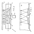
- the apparatus which is generally designated 10, is designed to measure a dimension of an elongate piece of material 12.
- the apparatus 10 is designed to measure the length of the material; however, the apparatus also could be used to measure the width of the material.
- the material can take any form, such as aluminum sheet or plate.
- the invention is especially useful in measuring the length of aluminum plate or sheet exiting from a hot mill. Such sheet or plate normally has a temperature in the vicinity of 800°F (425°C).
- the apparatus includes a conveyor 14 for positioning the material 12 within the measuring range of the apparatus.
- the conveyor in the illustrated embodiments, is a conventional conveyor that has individually powered rollers that can be energized individually or in groups to move the plate longitudinally back and forth so as to locate it in a desired position.
- the conveyor can be any reasonable width.
- An alignment mechanism (not illustrated) has pushers movable from the sides toward the center of the conveyor so as to properly position the plate along the centerline of the conveyor.
- a plurality of cameras, respectively designated 16, 18, 20, and 22, are mounted in fixed positions on a support surface or wall 24 of the building containing the apparatus 10. The cameras are horizontally and vertically spaced from the conveyor 14 so they will not be damaged by materials falling off of the conveyor.
- the viewing ranges 26, 28, 30, and 32 of the cameras define the measurement range of the apparatus. As can be seen from FIGURES 1 and 2, the viewing ranges of adjacent cameras overlap to ensure that there are no "dead" spaces within the measurement range.
- An arbitrary fixed point such as the centerline 34 of a stationary shear 36, is designated. At least one and preferably two alignment or calibration points, one of which designated 38 is illustrated, and located within the viewing range of each camera. The position of the calibration points are recorded for each camera after calibration of the system is complete. Any fixed point, the fixed shear in this case, is used as a reference point to calibrate all cameras.
- the portion of the measurement range covered by a camera is calibrated using an elongate piece of material having measuring points spaced along its length at known locations.
- the distance between one of the points and the fixed point is measured and entered into the computer. Then, the location of each of the remaining measuring points is sensed and entered into the computer. The computer automatically assigns values to the regions between the measured points.
- An operator control station 40 is located in the vicinity of the shear 36.
- the image depicted on screen 52 of monitor 50 is horizontally divided into a plurality of discrete elements or pixels 54.
- Each pixel schematically designated 1, 2, 3... N-2, N-1, N, respectively, corresponds to a discrete portion of the measuring range.
- the software used with the system depicts a horizontal line on the screen 52 that represents the centerline of the conveyor. The position of the line on the screen is vertically movable to correct for optical variations because of the location of the viewed object within the cameras field of view.
- the screen 52 is divided into 512 pixels.
- the cameras located to the left of the centerline 34 are fitted with lenses so that the width of each pixel corresponds with 0.6 inches of the measurement range and the cameras to the right of the center line are fitted with lenses so that each pixel represents 0.9 inches of the measurement range.
- FIGURE 3 one embodiment of a control system, generally designated 60, used with the present invention is depicted.
- the system 60 which is preferably contained within the control station 40, includes a central computer 62, an operator control station 64 that has a conventional keyboard control module, motor controls 66 (automatic or manual) for the conveyor 14, an automatic or manual control 68 for the shear 36, the TV monitor 50, and a switch 70 for selecting a particular camera.
- the control system 60 also includes appropriate memory devices 72 and peripheral devices 74, such as input/output devices, a printer, sensors, and data communication links.
- a piece of material 12 to be measured is positioned by the conveyor 14, by appropriate adjustments of the motor control 66, within the measurement range of the apparatus.
- the operator using camera switch 70, energizes a selected camera containing an edge or other desired portion of the material within its viewing range. If the edge is aligned with the viewing axis of the camera, it will appear as a straight line. If the edge is positioned to the left of the axis of the camera, it will be angled, as illustrated in FIGURE 5. If the edge is positioned to the right of the viewing axis, it will be angled in the opposite direction, as illustrated in FIGURE 6.
- the operator uses control 64, then moves indicator 80 into a position in alignment with the intersection of the edge of the material with the horizontal line representing centerline 82 of the conveyor, as best illustrated in FIGURE 6.
- the operator signals the computer so that the exact location of the edge with respect to the fixed point 34 can be calculated.
- the computer uses the relationship between the pixel containing the edge and the pixel's known distance from the fixed calibration point, calculates the distance of the edge from the fixed point.
- the operator then energizes the camera containing the opposite edge of the material and performs a similar measuring operation. If both locations are on the same side of the fixed point, the measured values are subtracted from each other to obtain the overall length of the material. On the other hand, if the determined values are on opposite sides of the fixed point, as in FIGURE 4, the values are added to obtain the overall length.
- the operator inputs into the computer, either manually or automatically, the desired lengths of materials to be cut from the plate.
- the computer calculates the locations of the cuts to be made to obtain the desired lengths.
- a selected camera is energized and the indicator 80 is positioned on the screen 52 at the desired location of the edge of the material where the first shear is performed.
- the operator using conveyor motor control 66, aligns an edge of the material with the pixel and then energizes shear control 68 to perform the shearing operation.
- the operator sometimes performs a series of small shearing operations prior to aligning the edge of the material with the pixel. This is required because, in one embodiment, the scrap system associated with the shear can handle only small pieces of scrap.
- the operator initially visually aligns the leading edge of the material to be measured with the calibration point of the apparatus. Such alignment is possible because of the location of the control station 40 adjacent the shear 36.
- the camera switch 70 uses the camera switch 70 to energise the camera depicting the trailing edge of the material. Determining the location of the trailing edge then automatically determines the overall length of the piece of material.
- One embodiment of the present invention has been used to successfully measure aluminum plate ranging in length between 72 inches (1.5m) and 1,900 inches (50m) and ranging in thickness between 0.25 inches (0.6cm) and 4.0 inches (10cm). Measurement accuracy has been within approximately 2.0 inches (5.0cm). Such accuracy is not adversely affected by variations in the thickness of the plate being measured.
- This embodiment utilises six cameras positioned on a wall of the building approximately 30 feet (9m) from the centre line of a 12-foot (3.6m) wide conveyor and approximately 28 feet (8.5m) above the conveying plane of the conveyor. The conveying plane is approximately 2 feet above floor level.
- Alignment of the cameras used in this system has been maintained over an extended period of time because the camera mounts were welded to structural portions of the building and have remained stationary, despite the harsh environmental conditions associated with processing hot aluminum plate.
- the cameras used with the system have been adjusted so that the cameras closest to and downstream of the shear have the highest resolution.
- Overall lengths less than 72 inches (1.5m) can be measured; however, there is no need to measure shorter overall lengths because the shear cannot be used to cut pieces shorter than 72 inches (1.5m).
- Pieces longer than 1,900 inches (50m) can be measured simply by adding more cameras or by increasing the viewing range of each camera (which will result in decreased accuracy).
- the invention in one embodiment, includes a system for rapidly verifying camera alignment.
- a system for rapidly verifying camera alignment With this system, easily visible targets are mounted on structural parts of the conveyor in regions where the fields of view of adjacent cameras overlap. Targets also are mounted at the extremities of the measuring range. Each camera can see two targets.
- the video screen has two additional small cross hairs that, during calibration of a particular camera, are aligned with the targets within the viewing range of the camera. Subsequently, when the particular camera is connected to the video screen, the cross hairs are displayed automatically in the position where the targets should be. If the cross hairs are aligned with the target, the camera is still in alignment with the measuring surface and the calibration, in practice, will be unchanged. If the alignments are in obvious error, the calibration will be inaccurate and will need to be corrected by realigning the offending camera and rechecking the calibration.
Landscapes
- Physics & Mathematics (AREA)
- General Physics & Mathematics (AREA)
- Length Measuring Devices By Optical Means (AREA)
Claims (14)
- Appareil de mesure de longueur sans contact (10) destiné à mesurer la longueur d'un élément allongé de matière comprenant :
un convoyeur (14) destiné à positionner un bord ou rive de la matière (12) à mesurer dans la plage ou portée de mesure de l'appareil ;
plusieurs caméras (16, 18, 20, 22) espacées par rapport au convoyeur, chaque caméra ayant une portée ou champ de visualisation (26, 28, 30, 32) définissant une portion de la portée de mesure de l'appareil ;
des moyens de calibrage (34, 38) destinés à calibrer la portée de visualisation de chaque caméra de sorte que chaque plage de visualisation couvre une portion de la portée de mesure qui possède une relation spatiale connue avec un point fixe (34) ;
un affichage (50) destiné à afficher toute vue de caméra sélectionnée qui représente au moins une portion de la portée de visualisation ;
des moyens indicateurs de bord associés à l'affichage ayant un indicateur (80) destiné à indiquer sur l'affichage la position d'un bord affiché d'un élément de matière, l'indicateur étant réglable dans la position sur l'affichage pour l'alignement sur un bord affiché par les moyens de commande (64) actionnés par un opérateur et des moyens (62) destinés à calculer la position précise du bord ou rive par rapport au point fixe, les moyens (62) destinés à calculer utilisant la position de l'indicateur sur l'affichage pour déterminer la distance entre le bord et le point fixe. - Appareil de mesure sans contact (10) selon la revendication 1, dans lequel les caméras (16, 18, 20, 22) sont des caméras vidéo espacées horizontalement et verticalement du convoyeur (14).
- Appareil (10) selon la revendication 1 ou 2, dans lequel les caméras (16, 18, 20, 22) sont montées dans une position fixe par rapport au convoyeur (14).
- Appareil (10) selon l'une quelconque des revendications précédentes, dans lequel les moyens de calibrage (34, 38) comprennent plusieurs points de calibrage (38) situés le long du convoyeur (14), chaque portée de visualisation (26, 28, 30, 32) comportant au moins un point de calibrage, chaque point de calibrage étant situé à une distance connue du point fixe (34).
- Appareil selon l'une quelconque des revendications précédentes, dans lequel au moins deux des portées de visualisation (26, 28, 30, 32) de caméras contiguës (16, 18, 20, 22) se chevauchent.
- Appareil selon la revendication 5, dans lequel les portées de visualisation (26, 28, 30, 32) de caméras contiguës (16, 18, 20, 22) se chevauchent.
- Appareil selon l'une quelconque des revendications précédentes, dans lequel le point fixe (34) est situé à l'intérieur de la portée de mesure.
- Appareil selon l'une quelconque des revendications précédentes, dans lequel la plage de mesure est sélectionnée de façon à être supérieure à l'élément le plus long de matière à mesurer.
- Appareil selon l'une quelconque des revendications précédentes, dans lequel l'affichage (50) comprend un écran vidéo (52) pouvant être relié de façon sélective à l'une des caméras (16, 18, 20, 22).
- Appareil selon l'une quelconque des revendications précédentes, apte notamment à la mesure d'un élément allongé d'aluminium.
- Procédé utilisant un appareil de mesure sans contact pour mesurer la longueur d'un élément de matière, l'appareil comportant plusieurs caméras (16, 18, 20, 22) dont les champs de visualisation (26, 28, 30, 32) définissent la portée ou champ de mesure de l'appareil, chaque portée de visualisation étant calibrée pour mesurer une portion de longueur connue de la plage de mesure ayant une relation spatiale connue avec un point fixe (34), un affichage (50) destiné à afficher la portée de visualisation d'une caméra sélectionnée, des moyens indicateurs de bord associés à chaque caméra ayant un indicateur (80) destiné à indiquer le bord affiché d'un élément de matière et des moyens (62) destinés à calculer la position du bord par rapport au point fixe et des moyens de commande (64) pour faire déplacer l'indicateur, le procédé comprenant les étapes consistant à :
positionner la matière (12) à mesurer dans la portée de mesure de l'appareil,
sélectionner l'une des caméras (16, 18, 20, 22) ayant un bord de la matière à l'intérieur de la plage de visualisation,
raccorder la caméra sélectionnée à l'affichage (50), et
utiliser le moyen de commande (64) pour aligner l'indicateur (80) sur l'affichage avec le bord affiché de la matière, les moyens (62) destinés à calculer déterminant la distance du bord par rapport au point fixe (34) en fonction de la position de l'indicateur (80) sur l'affichage. - Procédé selon la revendication 11, comprenant de plus la manipulation pour aligner l'indicateur (80) sur le bord affiché.
- Procédé selon la revendication 11 à 12, dans lequel le point fixe (34) est la position d'une cisaille pouvant être actionnée pour couper la matière.
- Procédé selon l'une quelconque des revendications 11 à 13, comprenant de plus le positionnement de l'indicateur à une position sur l'affichage qui correspond à une position sur le convoyeur à une distance souhaitée du point fixe (34) et à déplacer un bord de la matière en alignement avec l'indicateur (80) permettant ainsi de positionner le bord à une distance souhaitée par rapport au point fixe.
Applications Claiming Priority (2)
| Application Number | Priority Date | Filing Date | Title |
|---|---|---|---|
| US95285 | 1987-09-10 | ||
| US07/095,285 US4805019A (en) | 1987-09-10 | 1987-09-10 | Non-contact apparatus and method for measuring the length of aluminum sheet and plate |
Publications (2)
| Publication Number | Publication Date |
|---|---|
| EP0314276A1 EP0314276A1 (fr) | 1989-05-03 |
| EP0314276B1 true EP0314276B1 (fr) | 1992-12-09 |
Family
ID=22251160
Family Applications (1)
| Application Number | Title | Priority Date | Filing Date |
|---|---|---|---|
| EP88307848A Expired EP0314276B1 (fr) | 1987-09-10 | 1988-08-24 | Appareil et procédé de mesure sans contact |
Country Status (4)
| Country | Link |
|---|---|
| US (1) | US4805019A (fr) |
| EP (1) | EP0314276B1 (fr) |
| JP (1) | JPH01113604A (fr) |
| DE (1) | DE3876601T2 (fr) |
Families Citing this family (8)
| Publication number | Priority date | Publication date | Assignee | Title |
|---|---|---|---|---|
| US4924307A (en) * | 1988-06-03 | 1990-05-08 | Allen-Bradley Company, Inc. | Image processor |
| US5282268A (en) * | 1988-09-27 | 1994-01-25 | Allen-Bradley Company, Inc. | Video image storage system |
| US5239376A (en) * | 1992-02-11 | 1993-08-24 | Lake Superior Paper Industries | Web defect continuous surveillance system |
| US5394183A (en) * | 1992-05-05 | 1995-02-28 | Milliken Research Corporation | Method and apparatus for entering coordinates into a computer |
| US5717456A (en) * | 1995-03-06 | 1998-02-10 | Champion International Corporation | System for monitoring a continuous manufacturing process |
| US8860789B1 (en) * | 2011-12-09 | 2014-10-14 | Vic G. Rice | Apparatus for producing three dimensional images |
| KR102621405B1 (ko) | 2021-12-10 | 2024-01-05 | 이부락 | 인공고관절 |
| KR102621402B1 (ko) | 2021-12-10 | 2024-01-05 | 이부락 | 인공고관절 |
Family Cites Families (18)
| Publication number | Priority date | Publication date | Assignee | Title |
|---|---|---|---|---|
| SU148529A1 (ru) * | 1960-10-01 | 1961-11-30 | В.А. Рабинович | Телевизионный измеритель длины гор чего раската |
| US3428817A (en) * | 1964-11-27 | 1969-02-18 | Jones & Laughlin Steel Corp | Length measurer with plurality of photocells which are sequentially gated |
| US3676652A (en) * | 1970-02-18 | 1972-07-11 | Intertek Controls Inc | Electronic linear measuring device |
| BE752635A (fr) * | 1970-06-26 | 1970-12-28 | Centre Rech Metallurgique | Procede de mesure d'une dimension telle qu'une largeur, |
| US3714393A (en) * | 1971-07-20 | 1973-01-30 | Gen Electric | System for producing a constant number of pulses per unit length of traveling strip |
| GB1448611A (en) * | 1973-01-10 | 1976-09-08 | Nippon Kokan Kk | Method and apparatus for on-contact measurement of a gauge of a high temperature material |
| US4033697A (en) * | 1976-05-17 | 1977-07-05 | Reticon Corporation | Automatic exposure control for a luminous object monitor system |
| DE2725353A1 (de) * | 1977-06-04 | 1979-04-19 | Nukem Gmbh | Verfahren und vorrichtung zur laengenmessung von sich bewegenden formkoerpern, insbesondere von rotgluehenden halbzeugen |
| DE2819395C2 (de) * | 1978-05-03 | 1980-01-10 | Hoesch Werke Ag, 4600 Dortmund | Verfahren und Vorrichtung zum Bestimmen der Breite von Walzerzeugnissen |
| SE412286B (sv) * | 1978-07-10 | 1980-02-25 | Saab Scania Ab | Sett och anordning for fotoelektrisk avmetning av breder eller liknande geometriskt obestemda foremal |
| US4335439A (en) * | 1980-04-25 | 1982-06-15 | St Denis Andrew R | Weight monitoring device for strip metal stock |
| US4393401A (en) * | 1980-11-10 | 1983-07-12 | The Fairchild Engineering Company | Method and apparatus for dimensionally measuring articles |
| JPS57128809A (en) * | 1981-02-04 | 1982-08-10 | Toshiba Corp | Length measuring device for steel material |
| DE3125476C2 (de) * | 1981-06-29 | 1986-11-06 | Licentia Patent-Verwaltungs-Gmbh, 6000 Frankfurt | Steuerungsvorrichtung für eine Schere zum Abschneiden von bezüglich ihrer Breite unvollständig ausgebildeten Walzgutenden |
| US4476533A (en) * | 1981-07-08 | 1984-10-09 | Ball Corporation | Glassware gauging system |
| JPS5991586A (ja) * | 1982-11-16 | 1984-05-26 | Mitsubishi Electric Corp | 電子式視覚装置 |
| JPS60169704A (ja) * | 1984-02-15 | 1985-09-03 | Nippon Kokan Kk <Nkk> | 熱間鋼管の長さ測定方法 |
| US4691231A (en) * | 1985-10-01 | 1987-09-01 | Vistech Corporation | Bottle inspection system |
-
1987
- 1987-09-10 US US07/095,285 patent/US4805019A/en not_active Expired - Lifetime
-
1988
- 1988-08-24 EP EP88307848A patent/EP0314276B1/fr not_active Expired
- 1988-08-24 DE DE8888307848T patent/DE3876601T2/de not_active Expired - Fee Related
- 1988-09-09 JP JP63226288A patent/JPH01113604A/ja active Pending
Also Published As
| Publication number | Publication date |
|---|---|
| DE3876601D1 (de) | 1993-01-21 |
| JPH01113604A (ja) | 1989-05-02 |
| EP0314276A1 (fr) | 1989-05-03 |
| US4805019A (en) | 1989-02-14 |
| DE3876601T2 (de) | 1993-06-24 |
Similar Documents
| Publication | Publication Date | Title |
|---|---|---|
| US4557019A (en) | Automatic portion-cutting method and machine | |
| EP0429161B1 (fr) | Procédé et appareil pour contrôler l'entassement de matière à laminer, procédé et appareil pour fabriquer une feuille et procédé et appareil pour mesurer la température d'une feuille | |
| KR960010674B1 (ko) | 물체의 직선상의 위치의 비접촉 측정방법 및 그 장치 | |
| CA2002752C (fr) | Dispositif de controle de surface des brames | |
| US4497192A (en) | Process for cropping the head of self-luminous rolled material, especially metal strips and system for cropping the head | |
| EP2527785A1 (fr) | Procédé et dispositif de mesure de la planéité | |
| US4805019A (en) | Non-contact apparatus and method for measuring the length of aluminum sheet and plate | |
| EP0483362B1 (fr) | Systeme mesureur de la longueur d'une feuille | |
| EP0481496B1 (fr) | Procédé et dispositif pour mesurer les dimensions de profilés | |
| CS687583A2 (en) | Device for cutting head of a tunelling or winding machine position detection | |
| KR100495125B1 (ko) | 냉연 스트립의 평탄도 측정장치 및 방법 | |
| JPH08233538A (ja) | 寸法測定装置 | |
| KR20020002047A (ko) | 레이저 속도측정기를 이용한 핫바의 크롭절단장치 | |
| JPH0158444B2 (fr) | ||
| KR20040058742A (ko) | 냉연 평탄도 품질 향상을 위한 최적 목표 형상 설정시스템 및 그 방법 | |
| JPH0460405A (ja) | スタンド間多目的センサ | |
| US4204224A (en) | Process and apparatus for measuring the length of moving shaped articles particularly red-hot semifinished articles | |
| JP3573054B2 (ja) | 幅長さ計のオンライン測定精度検査方法 | |
| EP0546362B1 (fr) | Procédé de balayage et équipement avec des têtes de balayage pour mesurer et afficher l'épaisseur d'un film | |
| KR20110076021A (ko) | 엣저롤의 간격 및 마모 측정 장치 | |
| KR100564327B1 (ko) | 냉연 평탄도 측정 장치 및 측정 정도 향상 방법 | |
| EP0108845B1 (fr) | Dispositif de mesure | |
| JPH08128807A (ja) | 圧延機のロール変位測定方法及びその装置 | |
| CN210499501U (zh) | 一种基于视觉的精准快速裁剪设备 | |
| JPH05164548A (ja) | 急峻度測定方法 |
Legal Events
| Date | Code | Title | Description |
|---|---|---|---|
| PUAI | Public reference made under article 153(3) epc to a published international application that has entered the european phase |
Free format text: ORIGINAL CODE: 0009012 |
|
| AK | Designated contracting states |
Kind code of ref document: A1 Designated state(s): DE FR GB |
|
| 17P | Request for examination filed |
Effective date: 19891019 |
|
| 17Q | First examination report despatched |
Effective date: 19910416 |
|
| GRAA | (expected) grant |
Free format text: ORIGINAL CODE: 0009210 |
|
| AK | Designated contracting states |
Kind code of ref document: B1 Designated state(s): DE FR GB |
|
| REF | Corresponds to: |
Ref document number: 3876601 Country of ref document: DE Date of ref document: 19930121 |
|
| ET | Fr: translation filed | ||
| PLBE | No opposition filed within time limit |
Free format text: ORIGINAL CODE: 0009261 |
|
| STAA | Information on the status of an ep patent application or granted ep patent |
Free format text: STATUS: NO OPPOSITION FILED WITHIN TIME LIMIT |
|
| 26N | No opposition filed | ||
| PGFP | Annual fee paid to national office [announced via postgrant information from national office to epo] |
Ref country code: FR Payment date: 19940712 Year of fee payment: 7 |
|
| PGFP | Annual fee paid to national office [announced via postgrant information from national office to epo] |
Ref country code: DE Payment date: 19940725 Year of fee payment: 7 |
|
| PGFP | Annual fee paid to national office [announced via postgrant information from national office to epo] |
Ref country code: GB Payment date: 19940728 Year of fee payment: 7 |
|
| PG25 | Lapsed in a contracting state [announced via postgrant information from national office to epo] |
Ref country code: GB Effective date: 19950824 |
|
| GBPC | Gb: european patent ceased through non-payment of renewal fee |
Effective date: 19950824 |
|
| PG25 | Lapsed in a contracting state [announced via postgrant information from national office to epo] |
Ref country code: FR Effective date: 19960430 |
|
| PG25 | Lapsed in a contracting state [announced via postgrant information from national office to epo] |
Ref country code: DE Effective date: 19960501 |
|
| REG | Reference to a national code |
Ref country code: FR Ref legal event code: ST |