EP0314323B1 - Verkaufsautomat mit vergrössertem Verhältnis zwischen Schächtezahl und Wählmöglichkeiten - Google Patents
Verkaufsautomat mit vergrössertem Verhältnis zwischen Schächtezahl und Wählmöglichkeiten Download PDFInfo
- Publication number
- EP0314323B1 EP0314323B1 EP88309316A EP88309316A EP0314323B1 EP 0314323 B1 EP0314323 B1 EP 0314323B1 EP 88309316 A EP88309316 A EP 88309316A EP 88309316 A EP88309316 A EP 88309316A EP 0314323 B1 EP0314323 B1 EP 0314323B1
- Authority
- EP
- European Patent Office
- Prior art keywords
- wall portions
- product
- portions
- flow
- vend
- Prior art date
- Legal status (The legal status is an assumption and is not a legal conclusion. Google has not performed a legal analysis and makes no representation as to the accuracy of the status listed.)
- Expired - Lifetime
Links
- WYTGDNHDOZPMIW-RCBQFDQVSA-N alstonine Natural products C1=CC2=C3C=CC=CC3=NC2=C2N1C[C@H]1[C@H](C)OC=C(C(=O)OC)[C@H]1C2 WYTGDNHDOZPMIW-RCBQFDQVSA-N 0.000 claims description 33
- 238000005192 partition Methods 0.000 claims description 7
- 238000004891 communication Methods 0.000 claims description 4
- 238000001816 cooling Methods 0.000 claims description 3
- 230000007246 mechanism Effects 0.000 description 4
- 235000013361 beverage Nutrition 0.000 description 3
- 238000000071 blow moulding Methods 0.000 description 2
- 238000000034 method Methods 0.000 description 2
- 230000004323 axial length Effects 0.000 description 1
- 230000000903 blocking effect Effects 0.000 description 1
- 238000010276 construction Methods 0.000 description 1
- 235000014214 soft drink Nutrition 0.000 description 1
- 238000007666 vacuum forming Methods 0.000 description 1
Images

Classifications
-
- G—PHYSICS
- G07—CHECKING-DEVICES
- G07F—COIN-FREED OR LIKE APPARATUS
- G07F11/00—Coin-freed apparatus for dispensing, or the like, discrete articles
- G07F11/02—Coin-freed apparatus for dispensing, or the like, discrete articles from non-movable magazines
- G07F11/04—Coin-freed apparatus for dispensing, or the like, discrete articles from non-movable magazines in which magazines the articles are stored one vertically above the other
- G07F11/10—Coin-freed apparatus for dispensing, or the like, discrete articles from non-movable magazines in which magazines the articles are stored one vertically above the other two or more magazines having a common delivery chute
-
- G—PHYSICS
- G07—CHECKING-DEVICES
- G07F—COIN-FREED OR LIKE APPARATUS
- G07F11/00—Coin-freed apparatus for dispensing, or the like, discrete articles
- G07F11/02—Coin-freed apparatus for dispensing, or the like, discrete articles from non-movable magazines
- G07F11/34—Coin-freed apparatus for dispensing, or the like, discrete articles from non-movable magazines in which the magazines are of zig-zag form
Definitions
- the present invention relates to vend racks for a vending machine that store softdrink bottles or cans and feed the same in a cooled condition to a discharge port in the front of a vending machine in a uniform manner. More specifically, the present invention relates to modular serpentine vend rack mechanisms having the flexibility of storing selected numbers of vendable bottles or cans in a plurality of separately accessible serpentine vend columns of different capacities.
- One of the most widely used conventional vend racks for bottles and cans in a vending machine includes a plurality of side-by-side, vertical storage columns, each of which communicates with a discharge port in the front of a vending machine.
- the columns are disposed in parallel relationship, and the quantity of vendable products therein is usually controlled by dimensioning the width of the columns to receive either a double row of nestable bottles or cans or a single stacked row of bottles or cans.
- These columns may either be one-deep, two-deep or three-deep, depending on the depth on the vending machine cabinet.
- This conventional vend rack suffers from the disadvantage that there is little flexibility in choice of the number of vendable products that can be stored in the respective columns. Therefore, it is difficult to match product demand with storage capacity for any given column for a vending machine of this type which conventionally contains from five to nine selectable products and from seven to ten columns.
- product sales or demand is also influenced, for example, by the unique styling of a given vending machine. For instance, if the vending machine includes the use of an enlarged primary product selection button adjacent the coin slot of the vending machine, there will be a distinct need for more flexibility in product storage and delivery from the respective chutes of a vend rack. This need is to accommodate the vending format of that machine. The need to match product demand with storage capacity exists, however, for all machines which vend multiple products.
- US-A-2,272,682 discloses a vending machine structure which is adjustable so that it may accommodate packages of different sizes.
- a vend rack structure for product vending machines for delivering vendable products from a top loading position to a bottom dispensing position in a vending machine, comprising: upright wall portions having first means defining a plurality of serpentine paths thereon over a major extent of the vertical dimension thereof; second means defining a plurality of canted substantially horizontal chutes on said wall portions stacked one above the other and interconnecting the upper ends of respective ones of said serpentine paths to said top loading position at one side of said wall portions; said serpentine paths on adjacent ones of said wall portions defining serpentine product columns extending from said top loading position to said bottom dispensing position.
- the present invention is characterised in that said wall portions are hollow; in that said first means comprise hollow bosses extending outward from said wall portions and have the interior thereof in communication with said hollow wall portions; and in that said structure further comprises: port means formed in selected ones of said bosses connecting the interior thereof with said product columns over a predetermined portion thereof above said bottom dispensing position; flow means for permitting a flow of refrigerated air upward through said hollow wall portions and bosses and out through said port means for cooling a selected portion of said vendable products in said product columns prior to vending same; a refrigerated plenum having a ported top plate portion; circulation means in said plenum for forcing refrigerated air through said ported top plate portion; and bracket means for retaining the bottom ends of said wall portions, mounted on said top plate portion; said flow means comprising open bottom portions in said bracket means permitting said refrigerated air to flow therethrough and into said open bottom portions in said upright hollow wall portions and port means in said bracket means permitting said refrigerated air to flow therethrough and into said
- Certain preferred embodiments of the invention comprise a vend rack structure for product vending machines for delivering vendable products from a top loading position to a bottom dispensing position in a vending machine, comprising: upright wall portions having first means defining a plurality of serpentine paths thereon over a major extent of the vertical dimension thereof; second means defining a plurality of canted substantially horizontal chutes on said wall portions stacked one above the other and interconnecting the upper ends of respective ones of said serpentine paths to a said top loading position at one side of a said wall portion; and bracket means in a said vending machine for slidably receiving each of said wall portions, permitting selective removal and replacement thereof in said vending machine; said serpentine paths on adjacent ones of said wall portions being mirror images of one another, defining product columns extending from said loading position to said dispensing position, such that vendable products are supported therebetween to traverse said product columns from said loading position to said dispensing position; and said bracket means being adjustable laterally of said wall portions such that said product columns defined there between will accommodate vendable products
- the wall portions are hollow and the first means for defining the serpentine paths comprises hollow bosses extending outward from each wall portion with surfaces thereon defining the serpentine paths.
- the respective interiors of the hollow bosses and wall portions are in communication in a given wall portion and also are adapted to receive a flow of air from the refrigerated plenum of an associated vending machine.
- the bosses are perforated or ported to a selected height above the bottom of each wall portion to direct a flow of refrigerated air over the product stacked to that height in the product columns. Additionally, if desired, internal flow preventing partitions are formed in the hollow interiors to preclude airflow above that preselected height.
- the adjustable brackets contain flow ports cooperating with flow ports in the top plate of the refrigerated plenum of the vending machine to direct air flow induced by the evaporator fan into the hollow interiors of the walls and bosses.
- a vending machine 10 is shown as incorporating a vending cavity 12, located above a refrigerated plenum chamber 14, from which it is separated by the upper wall 16 of the plenum chamber 14.
- the plenum chamber 14 is provided with an evaporator fan 18 which forces air upwardly in the direction of the arrows shown, for a purpose to be hereinafter more fully described.
- the uppermost reach of the vending cavity 12 is provided with a top plate 20 which is substantially coextensive and parallel with the upper wall 16 on the plenum chamber 14.
- Slide-in serpentine vending rack modules 22 are provided within the vending cavity 12 in an array to be more fully described hereinafter. These serpentine vending modules 22 are slidably mounted in upper and lower mounting brackets 24 and 26, respectively, which in turn are attached to the top plate 20 in the vending cavity 12 and the upper wall 16 of the plenum chamber, respectively.
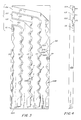
- the serpentine modules 22 each consist of four serpentine vend columns C1, C2, C3 and C4. Each of these columns comprises a substantially vertically disposed serpentine path with the columns C1 through C4 carrying products P1 through P4, respectively, with the respective columns varying in product capacity in the order of increasing number.
- column C1 contains less than column C2, which contains less product than column C3, which contains less product than column C4.
- each product column C1 through C4 is defined by a hollow vertical standard or wall portion 22A from which extend orthogonally disposed triangular bars 22B which are in an alternating pattern such that the apices 22C of the adjacent bars 22B are opposed and vertically spaced in an amount creating a serpentine path of travel for a product container traveling from top to bottom of a given product column C1-C4.
- the reaches R2, R3 and R4 at the tops of the columns C2, C3 and C4, respectively provide for a common loading area LP for all four of the columns C1-C4 since all of the columns terminate in a vertical stack adjacent an upper corner of the serpentine rack 22. This is clearly shown in Figure 2.
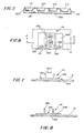
- serpentine vend rack 122 of the present invention is shown as including a plurality of continuous serpentine bosses extending orthogonally from the vertical walls 122A to form smooth transitional triangular portions 122B having apices 122C, with adjacent apices 122C in a given stack being oppositely disposed and vertically staggered such that a smooth serpentine path is formed from top to bottom in the vertically disposed portions of each of the columns IC1, IC2, IC3 and IC4.
- the columns are all loaded from a common vertical loading position ILP defined by integral partitions IR2, IR3 and IR4 defining boundaries between the four columns IC1 through IC4 and extending in a canted but substantially horizontal reach from the uppermost portion of the vertical extent of the said columns IC1 through IC 4 to the said vertical loading position ILP.
- the stanchion 122A forming the vend rack wall 122 is shown as being hollow at its lowermost portion to define an internal cavity 128 through which air may be forced to flow vertically within the vertical wall 122A through the cavity 128 by means of the evaporator fan 18 (shown in Figure 1) as will be hereinafter more fully described.
- a plurality of flow ports F are indicated as being drilled or formed in some or all of the substantially triangular portions 122B in the outermost surfaces thereof and a flow blocking partition FP is provided which extends laterally across the hollow structure 122A to preclude the flow of air from extending above that point.
- a flow blocking partition FP is provided which extends laterally across the hollow structure 122A to preclude the flow of air from extending above that point.
- the lack of perforations in the upper one-half or upper two-thirds of the triangular portions 122B will cause the flow of cooling air across the containers in the racks only in the lower one half to one third of the racks as the case may be.
- the hollow racks 122 are formed by blow molding or other similar techniques and a flat wall portion 122D such as illustrated in Figure 5 may be formed across the back of those racks designed for use as outboard rack portions while mirror image blow molded racks may be formed together to provide multi-sided centrally located rack portions.
- the innermost rack portions 22 include the triangular portions 22B extending from both sides thereof.
- the vend racks are formed by a blow molding with mirror image halves to form the multi-sided rack portions while the two outside rack portions also comprise mirror images of one another.
- Vacuum forming may also be used together with bonding techniques if the various rack portions are made in two or more parts.
- the vend racks are designed to be hollow.
- selected ones of the triangular extensions 22B are open-ended or perforated to permit air flow therefrom across the cans held therebetween.
- These racks may also include a flow impeding internal partition such as the partition FP in the embodiment of Figures 3-5.
- the lower mounting brackets 26A will be described since these brackets include air passages to permit flow of air into the hollow vertical standards or wall portions 22A and 122A in the various embodiments of the vend racks.
- the upper mounting brackets 24 are of substantially identical construction but do not require the presence of air vents therein.
- the mounting brackets 26 are shown as including upstanding open channels 26A integrally formed on flat plates 26B extending outboard of the upturned portions of the channels 26A and lying flush against the upper surface of the top wall portion 16 of the refrigerated plenum 14.
- An elongated slot 16A is formed in the top plate 16 of the plenum 14, under each of the brackets 26, for the purpose of permitting air to flow vertically outward from the plenum 14 under the influence of the evaporator fan 18 as indicated by the arrows in Figure 1 and as also indicated by the arrows in Figure 3, although the plenum is not shown in Figure 3.
- Cooperating flow ports 26C are formed within the channel 26A in the bracket 26 and are in communication with the elongated slots 16A in the top plate 16 such that air flowing from the plenum will flow upward through the bottom plate 26B of the brackets 26 through the flow ports 26C formed therein.
- the brackets are adjustable in a lateral direction, as indicated by the double ended arrows in Figures 6 and 7, by means of set screws 26D mounted in elongated laterally extending slots 26E in the base plate 26B of the brackets 26. These set screws 26D and slots 26E may be provided at desired intervals from the front to the back of the vending cavity 12 in the vending machine 10 as required for strength and security. Accordingly, as can be seen, the vend racks 22 and 122 are adapted to be slidably inserted into the brackets 26 and likewise, into the brackets 24, and slid into the vending cavity 12 of the vending machine 10.
- the brackets 26 are first adjusted by means of the set screws 26D and slots 26E to accommodate the proper distance between the vertical vend racks 22 and 122 to accommodate product cans P1 through P4 of any desirable length. In other words, the spacing between the vertical vend racks 22 or 122 is adjusted to accommodate the axial length of the product containers being dispensed.
- vend racks 22 or 122 As the case may be, inserted into the mounting brackets 24 and 26, which have been previously adjusted to the proper length to receive products P1 through P4 in each of the columns C1 through C4, respectively, it should be noted that the vend racks 22 or 122 are preferably placed into the vend cavity 12 with the loading portions LP or ILP, respectively, facing outward of the vend cavity within the view of a person servicing and loading the machine.
- the service person To load the machine, the service person simply places cans of product P1 through P4 in the respective columns C1 through C4 or IC1 through IC4, respectively, and permits the inserted containers to follow the serpentine vend rack path from the top loading position to the bottom thereof namely, the dispensing position, where they are engaged by conventional dispensing mechanisms (not shown). These mechanisms cooperate with the vending machine controls as is well known in the art to selectively dispense product from the bottom dispensing positions of various columns C1 through C4 and IC1 through IC4.
- the number of containers of a given product can be matched to the vend rate established by the marketplace. This will minimize the tendency of the supply of a given product to become exhausted far ahead of the supply of other products in a given multi-product machine.
- the number of containers of a given product can be matched to the vend rate established by the marketplace. This will minimize the tendency of the supply of a given product to become exhausted far ahead of the supply of other products in a given multi-product machine.
- the 495 containers of product there would be 95 containers of product P1, 110 containers of product P2, 120 containers of product P3 and 140 containers of product P4.
- Various other permutations and combinations of products can readily be made by mixing columns and products among the vending modules. Then, these selections are coordinated with the conventional vend select mechanisms and controls of the vending machine in a manner known in the art.
- the present invention provides a modular serpentine vend rack configuration for a plural product vending machine having the ability to store and supply a large number of high-demand, high-selling, vendable products in one or more large-capacity serpentine vend column configurations, and to store and supply lower-selling vendable products in lower capacity serpentine vend column configurations.
- vend rack configurations with greater flexibility for the variation of storage capacities of different types of vendable products such as canned or bottled beverages within a machine of the same overall storage columns as conventional machines; there being adjustments therein to accommodate variations in can or bottle size.
- vend rack structure for use in a multiple-product vending machine which facilitates matching of the capacity of respective configurations of vend columns with product demand so that the respective chutes containing the different products will theoretically become empty about the same point in time, thereby reducing the number of service calls for refilling the machine.
- vend rack which may be easily retrofit into existing vending machines which presently utilize conventional, vertical column vend racks.
Landscapes
- Physics & Mathematics (AREA)
- General Physics & Mathematics (AREA)
- Vending Machines For Individual Products (AREA)
- Control Of Vending Devices And Auxiliary Devices For Vending Devices (AREA)
Claims (2)
- Verkaufsstellage für Warenverkaufsautomaten (10) zur Abgabe von Verkaufswaren (P1-P4), ausgehend von einer oberen Aufgabeposition (LP; ILP) zu einer bodenseitigen Ausgabeposition in einem Verkaufsautomaten, welche folgendes aufweist:
aufrechtstehende Wandteile (22; 122), welche eine erste Einrichtung (22C; 122C) haben, welche eine Mehrzahl von serpentinenförmigen Bahnen über einen Großteil der vertikalen Abmessung hiervon hinweg bildet;
eine zweite Einrichtung (C1-C4; IC1-IC4), welche eine Mehrzahl von abgeschrägten, im wesentlichen horizontalen Schächten (R1-R4; IR1-IR-4) an den Wandteilen (22; 122) bilden, welche übereinanderliegend angeordnet sind und bei denen die oberen Enden der jeweiligen serpentinenförmigen Bahnen mit der oberen Aufgabeposition (LP-ILP) an einer Seite der Wandteile (122) verbunden sind;
die Serpentinenförmigen Bahnen auf benachbarten Wandteilen (22; 122) serpentinenförmige Warensäulen bilden, welche sich von der oberen Aufgabeposition (LP; ILP) zu der bodenseitigen Ausgabeposition erstrecken;
dadurch gekennzeichnet, daß die Wandteile hohl sind;
daß die erste Einrichtung hohle Vorsprünge aufweist, welche von den Wandteilen (22; 122) nach außen verlaufen und deren Inneres in Verbindung mit den hohlen Wandteilen steht; und daß die Stellage ferner aufweist:
eine Öffnungseinrichtung (F), welche in einem ausgewählten Vorsprung ausgebildet ist, welcher das Innere hiervon mit den Warensäulen über einen vorbestimmten Teil hiervon oberhalb der bodenseitigen Ausgabeposition verbindet;
eine Strömungsleiteinrichtung (16A, 26C), welche gestattet, daß ein Kühlluftstrom durch die hohlen Wandteile (22; 122) und die Vorsprünge und aus der Öffnungseinrichtung (F) zum Kühlen eines gewünschten Teils der Verkaufswaren (P1-P4) in den Warensäulen vor dem Verkauf derselben strömt;
ein Kühlraum (14), welcher ein oberes mit einer Öffnung versehenes Plattenteil (16) hat;
eine Umwälzeinrichtung in dem Raum (16), welche Kühlluft durch das mit der Öffnung versehene, obere Plattenteil (16) lenkt; und
eine Halteeinrichtung (26), welche die bodenseitigen Enden der Wandteile (22; 122) hält, die an dem oberen Plattenteil (16) angebracht sind;
die Strömungsleiteinrichtung offene, bodenseitige Teile (26C) in der Halteeinrichtung (26) aufweist, welche gestatten, daß Kühlluft durchgehen und in die offenen Bodenteile in den senkrecht stehenden, hohlen Wandteilen (22; 122) gehen kann, und daß die Öffnungseinrichtung (16A) in der Halteeinrichtung (26) gestattet, daß die Kühlluft durchgeht und in die offenen Bodenteile der senkrecht stehenden hohlen Wandteile (22; 122) gelangt. - Verkaufsstellage nach Anspruch 1, bei der folgendes vorgesehen ist:
die senkrecht stehenden, hohlen Wandteile (22; 122) innere Unterteilungseinrichtungen (FP) in einem vorbestimmten Abstand oberhalb des Bodenteils hiervon umfassen, um zu verhindern, daß der Kühlluftstrom im Innern des senkrecht stehenden hohlen Wandteils (22, 122) über den vorbestimmten Weg hinaus strömen kann, und
einer der Vorsprünge und eines der Verkaufserzeugnisse (P1-P4) jene sind, die unterhalb der inneren Unterteilungseinrichtung (FP) sind.
Applications Claiming Priority (2)
| Application Number | Priority Date | Filing Date | Title |
|---|---|---|---|
| US07/105,044 US4823983A (en) | 1987-10-06 | 1987-10-06 | Increased column/selectivity vender |
| US105044 | 1987-10-06 |
Publications (2)
| Publication Number | Publication Date |
|---|---|
| EP0314323A1 EP0314323A1 (de) | 1989-05-03 |
| EP0314323B1 true EP0314323B1 (de) | 1993-06-23 |
Family
ID=22303750
Family Applications (1)
| Application Number | Title | Priority Date | Filing Date |
|---|---|---|---|
| EP88309316A Expired - Lifetime EP0314323B1 (de) | 1987-10-06 | 1988-10-06 | Verkaufsautomat mit vergrössertem Verhältnis zwischen Schächtezahl und Wählmöglichkeiten |
Country Status (10)
| Country | Link |
|---|---|
| US (1) | US4823983A (de) |
| EP (1) | EP0314323B1 (de) |
| JP (1) | JPH07113992B2 (de) |
| AU (1) | AU613409B2 (de) |
| BR (1) | BR8805128A (de) |
| CA (1) | CA1320472C (de) |
| DE (1) | DE3882009T2 (de) |
| ES (1) | ES2041317T3 (de) |
| MX (1) | MX169937B (de) |
| ZA (1) | ZA887429B (de) |
Families Citing this family (20)
| Publication number | Priority date | Publication date | Assignee | Title |
|---|---|---|---|---|
| US4952109A (en) * | 1988-02-19 | 1990-08-28 | Excellon Automation | Modular feeding tray for vibrating conveyors |
| US4917264A (en) * | 1988-12-27 | 1990-04-17 | Fawn Engineering Corp. | Double-depth modified serpentine can vender |
| ES2043524B1 (es) * | 1991-09-26 | 1994-10-01 | Giner Miguel Mort | Expendedora de bebidas frescas envasadas, de funcionamiento con monedas. |
| US5368190A (en) * | 1992-03-30 | 1994-11-29 | Hieb; Larry E. | Apparatus for vending work objects |
| ES2070699B1 (es) * | 1992-12-04 | 1997-05-16 | Blanch Francesc Company | Maquina suministradora y refrigeradora de envases de bebidas. |
| DE19532728B4 (de) * | 1995-09-05 | 2010-03-18 | Deutsche Wurlitzer Gmbh | Warenautomat mit unterteilbarem Warenraum |
| US5813569A (en) * | 1996-03-12 | 1998-09-29 | Elite Licensing Inc. | Point-of-sale merchandiser |
| GB9903917D0 (en) | 1998-05-13 | 1999-04-14 | Gt B Components Ltd | Dispenser for chiller cabinets |
| US6510938B1 (en) * | 2000-11-28 | 2003-01-28 | Delaware Capital Formation, Inc. | Soft touch infeed |
| US8100292B2 (en) * | 2002-10-04 | 2012-01-24 | Crane Merchandising Systems, Inc. | Integrated column wall for a vending machine |
| US7100795B2 (en) * | 2002-10-04 | 2006-09-05 | Maytag Corporation | Adjustable rear spacer wall assembly for a vending machine |
| EP1587038B1 (de) * | 2004-04-15 | 2008-11-05 | DAMIAN S.r.l. | Verkaufsautomat für im wesentlichen zylindrisch geformte Gegenstände wie Flaschen, Getränkedosen o. ä. |
| JP4404012B2 (ja) * | 2005-05-31 | 2010-01-27 | 富士電機リテイルシステムズ株式会社 | 自動販売機 |
| US7810350B2 (en) * | 2007-03-22 | 2010-10-12 | Shelton Andrew C | Beverage dispensing cooler |
| US20100133969A1 (en) * | 2008-12-01 | 2010-06-03 | Genesis Manufacturing | Vending machine for dispensing cylindrical Articles |
| CN104077845A (zh) * | 2013-03-28 | 2014-10-01 | 鸿富锦精密工业(武汉)有限公司 | 自动售货机货道结构 |
| WO2014199238A2 (en) * | 2013-05-31 | 2014-12-18 | George Plakas | Apparatuses for dispensing objects and methods of manufacturing and uses thereof |
| US10068408B2 (en) * | 2015-04-13 | 2018-09-04 | Automated Merchandising Systems Inc. | Vending machine adjustable depth retainer |
| CA3121454C (en) | 2017-01-30 | 2026-01-20 | Ammunition Management Technologies Inc. | Ammunitions magazine loader with integrated adaptor |
| US11982506B2 (en) | 2021-11-22 | 2024-05-14 | Ammunition Management Technologies Inc. | Magazine ammunition unloader and magazine container for magazine ammunition unloader |
Family Cites Families (21)
| Publication number | Priority date | Publication date | Assignee | Title |
|---|---|---|---|---|
| US1736057A (en) * | 1927-11-11 | 1929-11-19 | D A Ebinger Sanitary Mfg Co | Refrigerated bottle dispenser |
| US2272682A (en) * | 1939-08-25 | 1942-02-10 | Joseph W Srodulski | Vending machine compartment structure |
| US2785828A (en) * | 1952-10-24 | 1957-03-19 | Seth B Atwood | Dispensing machine |
| US3085712A (en) * | 1959-02-20 | 1963-04-16 | Skumawitz Max | Automatic vending machines |
| US3075670A (en) * | 1959-10-07 | 1963-01-29 | Brugger Franz | Multiple compartment refrigeration installation |
| US3145066A (en) * | 1962-07-12 | 1964-08-18 | L W Menzimer | Vending machines |
| US3498497A (en) * | 1968-04-15 | 1970-03-03 | Vendo Co | Double-depth serpentine can vender |
| BE792391A (fr) * | 1971-12-08 | 1973-06-07 | Millies Clarence F | Dispositif destine a adapter un distributeur automatique a des objets de dimensions differentes |
| US4171066A (en) * | 1976-05-17 | 1979-10-16 | Matsushita Reiki Co., Ltd. | Automatic vending machine capable of heating vended goods |
| US4287992A (en) * | 1978-07-11 | 1981-09-08 | Shimoda Kogyo, Ltd. | Rack structure |
| US4245755A (en) * | 1979-11-16 | 1981-01-20 | The Vendo Company | Product storage space apportioning apparatus for product dispensing machines |
| US4303179A (en) * | 1980-01-04 | 1981-12-01 | La Crosse Cooler Company | High density can stack for automatic can venders |
| JPS6029439B2 (ja) * | 1980-11-26 | 1985-07-10 | 富士電機株式会社 | 自動販売機の商品収納棚 |
| US4380130A (en) * | 1981-03-17 | 1983-04-19 | The Coca-Cola Company | Display panels for vending machines |
| US4423828A (en) * | 1981-07-20 | 1984-01-03 | Fuji Electric Company, Ltd. | Goods discharge mechanism and goods storage and discharge system of automatic vending machine |
| US4485937A (en) * | 1982-04-22 | 1984-12-04 | Adams Morgan A | Can dispensing apparatus |
| US4586633A (en) * | 1983-04-07 | 1986-05-06 | Coin Acceptors, Inc. | Vending machine storage rack assembly |
| US4561564A (en) * | 1984-08-23 | 1985-12-31 | Sanden Corporation | Article dispensing mechanism for a vending machine or the like |
| US4632257A (en) * | 1985-01-07 | 1986-12-30 | Sanden Corporation | Article dispensing mechanism for a vending machine |
| US4763963A (en) * | 1986-07-25 | 1988-08-16 | The Coca-Cola Company | Skewed serpentine multi-package product storage rack |
| US4722455A (en) * | 1986-09-24 | 1988-02-02 | The Coca-Cola Company | Increased column/selectivity vender |
-
1987
- 1987-10-06 US US07/105,044 patent/US4823983A/en not_active Expired - Fee Related
-
1988
- 1988-10-04 ZA ZA887429A patent/ZA887429B/xx unknown
- 1988-10-05 JP JP63250005A patent/JPH07113992B2/ja not_active Expired - Lifetime
- 1988-10-05 BR BR8805128A patent/BR8805128A/pt not_active IP Right Cessation
- 1988-10-05 CA CA000579329A patent/CA1320472C/en not_active Expired - Fee Related
- 1988-10-05 MX MX013304A patent/MX169937B/es unknown
- 1988-10-06 DE DE88309316T patent/DE3882009T2/de not_active Expired - Fee Related
- 1988-10-06 EP EP88309316A patent/EP0314323B1/de not_active Expired - Lifetime
- 1988-10-06 AU AU23453/88A patent/AU613409B2/en not_active Ceased
- 1988-10-06 ES ES198888309316T patent/ES2041317T3/es not_active Expired - Lifetime
Also Published As
| Publication number | Publication date |
|---|---|
| BR8805128A (pt) | 1989-05-16 |
| ZA887429B (en) | 1989-06-28 |
| CA1320472C (en) | 1993-07-20 |
| JPH01128196A (ja) | 1989-05-19 |
| DE3882009T2 (de) | 1993-12-16 |
| ES2041317T3 (es) | 1993-11-16 |
| AU2345388A (en) | 1989-04-06 |
| JPH07113992B2 (ja) | 1995-12-06 |
| AU613409B2 (en) | 1991-08-01 |
| US4823983A (en) | 1989-04-25 |
| EP0314323A1 (de) | 1989-05-03 |
| DE3882009D1 (de) | 1993-07-29 |
| MX169937B (es) | 1993-08-02 |
Similar Documents
| Publication | Publication Date | Title |
|---|---|---|
| EP0314323B1 (de) | Verkaufsautomat mit vergrössertem Verhältnis zwischen Schächtezahl und Wählmöglichkeiten | |
| US4998628A (en) | Gravity-operated bottle and can dispensing rack | |
| US5996838A (en) | Vending machine | |
| US5878862A (en) | Product delivery device | |
| EP2158825A1 (de) | Warenauslagesystem | |
| US4763963A (en) | Skewed serpentine multi-package product storage rack | |
| US6431398B1 (en) | Dispensing mean for vending machine | |
| EP0853456B1 (de) | Kühltheke mit schubladen | |
| US4705176A (en) | Article vendor with adjustable column transfer provision for accomodating locally-prevalent space-to-sales ratio | |
| EP0261678B1 (de) | Verkaufsapparat mit vergrösserter Stapelauswahl | |
| US4245755A (en) | Product storage space apportioning apparatus for product dispensing machines | |
| US4927055A (en) | Increased column/selectivity vender | |
| JP4333025B2 (ja) | 自動販売機の直積式商品収納ラック | |
| US3498498A (en) | Split column package storage mechanism for cigarette vending machine | |
| JP3769349B2 (ja) | 自動販売機 | |
| EP0261677B1 (de) | Verkaufsapparat mit vergrösserter Stapelauswahl | |
| KR19990021132U (ko) | 자동 판매기의 상품 투입 장치 | |
| JP2002245531A (ja) | 自動販売機 | |
| JP2896010B2 (ja) | 自動販売機 | |
| JP3478197B2 (ja) | 自動販売機の商品収納払出装置 | |
| JP3582526B2 (ja) | 自動販売機の直積式商品収納ラック | |
| JPH0219896Y2 (de) | ||
| JP2005018106A (ja) | 自動販売機の直積式商品収納ラック | |
| JPH03278293A (ja) | 自動販売機 | |
| KR19990050106A (ko) | 자동판매기의 상품랙크 |
Legal Events
| Date | Code | Title | Description |
|---|---|---|---|
| PUAI | Public reference made under article 153(3) epc to a published international application that has entered the european phase |
Free format text: ORIGINAL CODE: 0009012 |
|
| AK | Designated contracting states |
Kind code of ref document: A1 Designated state(s): DE ES FR GB IT |
|
| 17P | Request for examination filed |
Effective date: 19890717 |
|
| 17Q | First examination report despatched |
Effective date: 19911024 |
|
| GRAA | (expected) grant |
Free format text: ORIGINAL CODE: 0009210 |
|
| AK | Designated contracting states |
Kind code of ref document: B1 Designated state(s): DE ES FR GB IT |
|
| ITF | It: translation for a ep patent filed | ||
| REF | Corresponds to: |
Ref document number: 3882009 Country of ref document: DE Date of ref document: 19930729 |
|
| ET | Fr: translation filed | ||
| REG | Reference to a national code |
Ref country code: ES Ref legal event code: FG2A Ref document number: 2041317 Country of ref document: ES Kind code of ref document: T3 |
|
| PLBE | No opposition filed within time limit |
Free format text: ORIGINAL CODE: 0009261 |
|
| STAA | Information on the status of an ep patent application or granted ep patent |
Free format text: STATUS: NO OPPOSITION FILED WITHIN TIME LIMIT |
|
| 26N | No opposition filed | ||
| PGFP | Annual fee paid to national office [announced via postgrant information from national office to epo] |
Ref country code: GB Payment date: 19990913 Year of fee payment: 12 |
|
| PGFP | Annual fee paid to national office [announced via postgrant information from national office to epo] |
Ref country code: FR Payment date: 19990920 Year of fee payment: 12 |
|
| PGFP | Annual fee paid to national office [announced via postgrant information from national office to epo] |
Ref country code: DE Payment date: 19990927 Year of fee payment: 12 |
|
| PGFP | Annual fee paid to national office [announced via postgrant information from national office to epo] |
Ref country code: ES Payment date: 19991020 Year of fee payment: 12 |
|
| PG25 | Lapsed in a contracting state [announced via postgrant information from national office to epo] |
Ref country code: GB Free format text: LAPSE BECAUSE OF NON-PAYMENT OF DUE FEES Effective date: 20001006 |
|
| PG25 | Lapsed in a contracting state [announced via postgrant information from national office to epo] |
Ref country code: ES Free format text: LAPSE BECAUSE OF NON-PAYMENT OF DUE FEES Effective date: 20001007 |
|
| GBPC | Gb: european patent ceased through non-payment of renewal fee |
Effective date: 20001006 |
|
| PG25 | Lapsed in a contracting state [announced via postgrant information from national office to epo] |
Ref country code: FR Free format text: LAPSE BECAUSE OF NON-PAYMENT OF DUE FEES Effective date: 20010629 |
|
| PG25 | Lapsed in a contracting state [announced via postgrant information from national office to epo] |
Ref country code: DE Free format text: LAPSE BECAUSE OF NON-PAYMENT OF DUE FEES Effective date: 20010703 |
|
| REG | Reference to a national code |
Ref country code: FR Ref legal event code: ST |
|
| REG | Reference to a national code |
Ref country code: ES Ref legal event code: FD2A Effective date: 20011113 |
|
| PG25 | Lapsed in a contracting state [announced via postgrant information from national office to epo] |
Ref country code: IT Free format text: LAPSE BECAUSE OF NON-PAYMENT OF DUE FEES;WARNING: LAPSES OF ITALIAN PATENTS WITH EFFECTIVE DATE BEFORE 2007 MAY HAVE OCCURRED AT ANY TIME BEFORE 2007. THE CORRECT EFFECTIVE DATE MAY BE DIFFERENT FROM THE ONE RECORDED. Effective date: 20051006 |